Tylö SENSE PLUS ELITE Sauna Heater Mode d'emploi
- Taper
- Mode d'emploi

2018-09-12
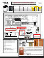
SENSE PLUS ELITE Quick-Start Tip Sheet
This page to be used in conjuction with Tylo Full Manual included
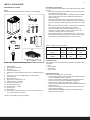
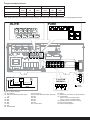
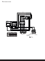
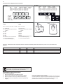
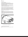
CONNECTION/WIRING DIAGRAM
TAB 208 V 1 Phase 240 V 1 Phase
Model Amperage
Amps
Output
kW
Wire Size
AWG
Amps/
Breaker
Output
kW
Wire Size
AWG
Sense - U 7 26 5.3 10 30/40 7.0 8
Sense - U 8 30 6.3 8 35/50 8.3 8
Note: Heating elements do not change for voltage changes. The heater output will change
based on the voltage applied to heater. Most North American homes are 240v.
13
B
B
41
40
120 V~
14 AWG
Max. 6 Amp.
G
5.3-8.3 kW
208/240 V~
x 3
10
13
14
15
12
RJ10 4P4C
3 x 14 AWG
RJ10 4P4C
RJ10 4P4C
max 300 feet Pure Control
*
*
Connect Control cable (flat)
to jack 9 on circuit board.
Connect NTC Sensor cable
(round) to jack 1 on circuit board.
In order for control
to operate light, a
separate 120V supply
must be provided and
connected to heater
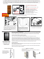
Sensor
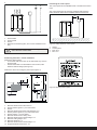
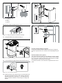
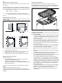
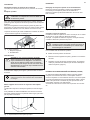
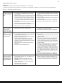
Installation Tip
1. (1) If using Sensor Cover, you are supposed to feed the
sensor wire through the sensor holder FIRST before running
wire inside the wall. If not done first, do one of the following
2. (2) Sensor with metal tab is usually installed without cover
with one screw through the sensor tab directly to the finishe
wall.
3. (3) Mount sensor holder close to sensor. Surface mount
sensor as show in picture. Install cover to hide sensor wire and
any hole made for wire.
4. (4) DO NOT install cover on top of sensor after installation.
It can affect heat sensitivity and cause heater high limit to trip
(1)
(2) (3)
(4)
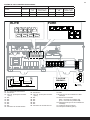
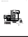
Figure 19: Wiring diagram
1. NTC Sensor - Sense Pure. (jack # 1)
2. External Switch (Optional jack # 2)
3. Door jumper pre-installed (jack # 3)
4. N/A
5. N/A
6. N/A
7. N/A
8. Pure Control (jack # 8)
9. N/A
10. Heater
11. Terminal for connection of electrical cable
12. Pure Control (jack # 8)
13. Sensor - Sense Pure (jack # 1)
14. Light/terminal for connection of light
15. Door Switch is not required for N. America
16. External On/Off Switch (option
2900 5282
11
1 2
6 7 8 9
3 4 5
Confirm
three copper
conectors
installed

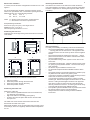
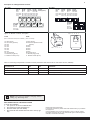
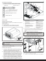
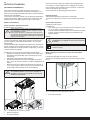
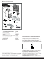
Elite Control Installation Instructions
The control panel can be installed inside or outside the sauna room. If the control is installed inside
the room, install no higher than 3’ (90 cm) above the floo . No closer than 12” (30 cm) to heater.
Installation Without Mounting Bracket (Typical)
Cut a 1-3/16” (3 cm) hole through the wall big enough for the control panel connector.
Attach the double-sided adhesive to the control panel. Before applying the control to the wall, con-
nect it to the heater and electrically test everything first. Clean the surface where the control will b
applied to remove all dust. Remove the protective backing from the adhesive. Silicone sealant can
be applied in the groove on the back of the panel as an extra seal. Connect the control wire, push the
excess wire through the hole in the wall and press the control panel firmly to the wall
Installation Bracket
Use the mounting bracket as a template to mark screws holes on the wall. Tighten the screws a little
until the bracket is nearly secured.
Remove the bracket from the wall. Use adhesive to mount the control to the bracket. Remember to
position the switch according to the picture.
Install without bracket
Control stuck directly to
the wall. Control cable
in the stud cavity.
Installation without Bracket Installation with Bracket
Install with bracket
Generally only used when control wire is surface mounted; i.e.
solid log style outdoor sauna.
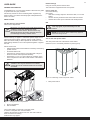
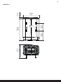
Elite Control Location
The control panel can be
installed inside or outside
of the sauna room.
(Outside is Typical)
1. Minimum distance from side wall: 4” (100 mm)
2. Sensor position alt 1: 3” (75 mm) from heater
3.
4. Minimum distance from back wall (with legs): 4” (100
Sensor
mm)
5. Sensor position alt 2: 3” (75 mm) from heater front
6. Sensor position: 1” (25 mm) from ceiling
7. Minimum distance from ceiling: 44” (1100 mm)
8. Minimum distance from heater guard: 4” (100 mm)
9. Minimum ceiling height: 75” (1900 mm)
10. Minimum distance: 1” (25 mm)
11. Minimum distance from heater guard: 2” (50 mm)
12. Distance from floor: 7” (175 mm)
Figure 9: Resetting the temperature cut-out
1. Temperature cut-out sauna heater
1
1
4
8
11
10
12
2
6
5
9
7
3
3
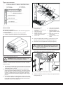
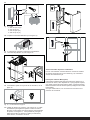
Figure 11: Attaching the brackets to the heater
Unscrew the first two screws on the back of
the heater and screw bracket to heater one at
a time. see Fig. 11.Note: If all the screws on
the back are unscrewed simultaneously, the
back plate may come loose.
** Pure Control distance to heater is max 300 feet
Figure 3: Position the sensor according the picture.
Sensor Location:
3" from heater.
1" down from ceiling
Main Power Switch: On/Off Knob
comes packed inside rock tray.
Field install. Turn knob to turn on
heater.
sensor location:
1” down from ceiling
3” to front or side of
heater; not in corner..
1. CAUTION: Heater junction box can be a tight fit. Make sure no bare wires come in to contact with circuit board, on/off switch or any
other heater components. Extra care should be taken when closing junction box cover to ensure wires are not being pushed out of position.
2. Some prefer or are required to make a weather-proof connection. If so, you may use Liquid tight conduit for the wire exposed
within the sauna. For more flexibility, you can install weather proof junction box inside sauna below heater and use flexible SOOW wire to
connect to heater

2016-10-18
2900 5280
SENSE PURE/ELITE USA
ENGLISH
INSTALLATION / USER GUIDE
FRANÇAIS
NOTICE D’INSTALLATION ET D’UTIL-
ISATION

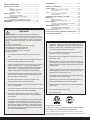
2
INSTALLATION GUIDE................................................ 3
BEFORE INSTALLATION .................................................... 3
Parts ....................................................................... 3
Installation requirements ........................................ 3
Installation tools ...................................................... 3
Installation planning ............................................... 3
INSTALLATION .................................................................... 6
Sauna heater installation ........................ ................ 6
External ON/OFF switch (option) ........................... 7
CONNECTION/WIRING ....................................................... 8
Description of cabling/modular contacts ................. 9
SELF-INSPECTION OF THE INSTALLATION................... 9
DIMENSIONS.......................................................................... 10
USER GUIDE............................................................... 11
GENERAL INFORMATION .................................................. 11
PRIOR TO USE ..................................................................... 11
The fi rst time you use the heater ............................ 1 1
Prior to each use .................................................... 11
USE ........................................................................................ 12
The control panel in general.................................... 12
Other functions........................................................ 12
EXTERNAL ON/OFF SWITCH (OPTION)........................... 12
AFTER USE .......................................................................... 12
Empty the reservoir................................................. 12
Switch off main power switch.................................. 12
MAINTENANCE .................................................................... 12
Cleaning the fragrance holder and air humidifi er
......... 12
Check the stone compartment ............................... 12
TROUBLESHOOTING ......................................................... 13
Troubleshooting the control panel .......................... 13
Troubleshooting the sauna heater.......................... 14
SPARE PARTS LIST ............................................................ 15
ROHS (RESTRICTION OF HAZARDOUS SUBSTANCES)
...... 15
HEATER WIRING DIAGRAM
................................................... 16
WARNING!
• Electric Shock Hazard - High voltage exists within this
equipment. There are no user serviceable parts in this
equipment. All installation and service to this equipment
should be performed by qualifi ed licensed personnel in
accordance with local and national codes.
• Do not construct sauna room so as to restrict air fl ow
through the bottom of the heater.
• Packing the rocks too tightly may cause the heater high
limit switch to trip.
• Maintain minimum clearance from heater to wooden sur-
faces (benches, side walls, heater fence etc.). Mounting
brackets supplied. Provides proper clearance from wall
behind heater.
• Use only copper wire of the size and type indicated in the
Heater Specifi cation Chart and the temperature rating
indicated on the heater junction box.
• A guardrail or fence is required around the heater to pre-
vent burns from accidental contact.
• All heaters and controls must be grounded per NEC to
prevent electrical shock in case of unit failure.
• Electrical outlets or receptacle must not be installed in a
sauna room.
• Do not locate benches over heater.
• For household only.
Keep this user guide!
In the event of any problems, please contact the re-
tailer where you purchased the equipment.
© This publication may not be reproduced, in part or in whole, without
the written permission of Tylö. Tylö reserves the right to make changes in
materials, construction and design.
* Hyperthermia occurs when the internal temperature of
the body reaches a level several degrees above the normal
temperature of 98.6° F. The symptoms of hypothermia include
an increase in the internal temperature of the body, dizziness,
lethargy, drowsiness and fainting. The eff ect of hyperthermia
include:
a) Failure to perceive heat;
b) Failure to recognize the need of exit the room;
c) Unawareness of impending hazard;
d) Fatal damage of pregnant women;
e) Physical inability to exit the room; and
f) Unconsciousness
• Do not take a sauna if using alcohol, drugs or medica-
tions.
• Pregnant women or persons with poor health should con-
sult their physician before using any sauna.
• Caution fi re hazard: Do not use the sauna room for drying
clothes, bathing suits, etc. Do not hang towels above
heater or place any object other than the rocks supplied
on the heater. If any darkening of the wall around the
heater is noticed discontinue sauna use immediately.
• Inspect sauna regularly for required maintenance to heat-
er, control and benches. Replace wood surfaces which
show any signs of deterioration.
• The heater gets extremely hot during operation and
should not be touched or burns may result.
• Minors should be adequately supervised whenever near a
hot or warming sauna.
• Fire sprinkler systems used inside any sauna room should
be properly rated for sauna room temperatures.
• Do not pour chlorinated pool or spa water on heater.
Excessive water use on heater may cause damage and
void warranty.
• This appliance is not intended for use by persons (includ-
ing children) with reduced physical, sensory or mental
capabilities, or lack of experience and knowledge, unless
they have been given supervision or instruction concern-
ing use of the appliance by a person responsible for their
safety. Children should be supervised to ensure that they
do not play with the appliance.

3
INSTALLATION GUIDE
BEFORE INSTALLATION
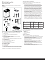
Parts
Check that the following parts are included in the packaging:
Figure 1: Sauna heater/control panel parts
1. Sauna heater
2. Herb bowl/air humidifi er
3. Brackets x 4
4. Lock screw B8x9.5 x 1
5. Warning and Caution plates for the room in multiple languag-
es
6. Screws B 4 x 6.5 x 6 for Warning and Caution plates
7. Connectors x 3
8. Bracket screws x 4
9. NTC Sensor, cable length 4 m
10. Clips TC (3-5) x 10 pieces
11. Plastic plugs 25x5 x 2 pcs
12. Screws B6x25 x 2 pcs
13. Screw B4x6,5 x 1 piece
14. Sensor cover
15. Rock guard
16. Protection hose Ø14x150 mm x 3 pcs, for RJ10 cables (sen-
sor, control panel, door switch)
Contact your dealer if anything is missing.
Installation tools
The following tools and materials are needed for installation and
connection:
• level
• tape measure
• electric drill
• screw drivers
Installation planning
Before starting to install your sauna heater:
• Plan the sauna heater positioning (see the Heater positioning
- normal installation section, page 4).
• Plan the control panel positioning (see the attached instruc-
tions for the control panel for allowable positioning).
• Plan the sensor positioning (see Figure 3, page 4).
• Position the air intake vent (see the Air intake vent positioning
section, page 5).
• Position the air exhaust vent (see the Air exhaust vent posi-
tioning section, page 5).
• Plan the electrical installation (see the Connection/wiring
diagram section, page 8).
2
8
67
15
5
1
34
9
10 11 12
13
14
16
Table 1: Voltage and sauna volume
Model Voltage Sauna volume
min. cu.ft.
Sauna volume
max. cu.ft.
Sense U 7 Elite/Pure
(SPU7)
208 V
240 V
175
175
265
320
Sense U 8 Elite/Pure
(SPU8)
208 V
240 V
250
250
360
440
Installation requirements
To ensure safe use of the heater, check that the following criteria
are met:
• Electrical wiring should be installed in accordance with NEC
and all state and local codes.
• Fuse size (A) and power cable size (AWG) must be suitable
for the heater (see The section called Connection/wiring
diagram, Page 8.
• The sauna ventilation must comply with the instructions in
this manual (see The section called Positioning the inlet vent,
Page 5, The section called Positioning the outlet vent, Page
5).
• The position of the sauna heater, control panel, and sensors
must comply with the instructions in this manual.
• The heater output (kW) must be suitable for the sauna
volume (cu.ft.) (See Table 1, Page 3). The minimum and
maximum volumes must not be exceeded.
• NOTE: A GFCI device is not required by ETL. A GFCI may
be installed if required by local codes. However, GFCI devic-
es will tend to nuisance trip during use of the product.

4
1
3
2
4
Figure 2: Schematic diagram of installation
1. Sauna heater
2. Control panel
3. Sensor
4. External on/off switch (option, door contact needed for func-
tion)
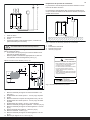
Positioning the heater - normal installation
Position the sauna heater:
• on the same wall as the door (or the side wall if very close to
the door wall).
• Position the heater at a safe distance from the fl oor, side
walls and interior fi ttings (see Figure 3).
Position the sensor according the picture (see Figure 3).
1
4
8
11
10
12
2
6
5
9
7
3
3
Figure 3: Positioning the heater - normal installation
1. Minimum distance from side wall: 4 in
2. Sensor position (option 1): 3 in from heater
3. Sensor
4. Minimum distance from back wall (with legs): 4 in
5. Sensor position (option 2): 3 in from heater front
6. Sensor position: 1 in from ceiling
7. Minimum distance from ceiling: 44 in
8. Minimum distance from interior fi ttings: 4 in
9. Minimum ceiling height: 75 in
10. Minimum distance: 1 in
11. Minimum distance from interior fi ttings: 2 in
12. Suggested distance from fl oor: 7 in
Positioning the control panel
The control panel can be installed inside or outside of the sauna
room.
The control panel must be correctly positioned with regard to
safety distances below when installed inside the sauna room
Figure 4: Safety distance, control panel
1. Heater
2. Control panel
3. Max. 36 in
4. Min. 12 in
1
2
4
3
DANGER! No more than one heater may be instal-
led in the same sauna cabin.
Figure 5: Warning/Caution plate

5
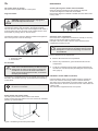
Sauna room ventilation
In a sauna, the air should be changed about 6 times an hour. See
Figure 6.
It is recommended that ventilation openings meet the require-
ments of UL Specifi cation 875. The minimum opening should be
determined using one of the following formulas:
For R< 31, V ≥ 9 .3
For R ≥ 31, V ≥ 0.3*R
where R = the fl oor area of the room in square feet and
V = the minimum vent size in square inches
ExampleVenting Calculation:
Room is 54 sq.ft.(9 ft. by 6 ft.) 54 is larger than 31.
Multiple 54 x 0.3 = 16.2 sq. in.
Vent size opening should be 4 in x 4 in.
Positioning the inlet vent
Install the inlet vent straight through the wall under the centerline
of the heater.
Figure 6: Positioning the air intake and exhaust vents
1. Inlet vent position.
2. Outlet vent position through the sauna wall.
3. Outlet vent position through the cavity.
4. Outlet vent position via duct.
Positioning the outlet vent
Position the outlet vent
• at the maximum possible distance from the air intake vent,
e.g. diagonally (see Figure 6).
• high on the wall or in the ceiling (see Figure 6).
• so that it vents into the space that the door and air intake
vent open into.
The outlet vent must have the same area as the inlet vent.
Ensure that the outlet vent is open.
Mechanical ventilation is not recommended due to the risk of poor
air exchange, which can negatively aff ect the heater temperature
cut-out.
Removing the Rock Guard
Unscrew the two screws on the side of the heater and lift the
rock guard upwards, see Figure 7. (This is necessary when fi lling
the stone compartment or cleaning the fragrance holder and air
humidifi er).
1 2
34
Figure 7: Removing the Rock Guard
Room construction
For safety and reliability, the following rules must be addressed.
• The enclosed WARNING: Reduce the risk of overheating
… warning plate must be mounted on or alongside the door
outside the sauna room at about eye level. Use the supplied
screws.
• The enclosed CAUTION: Reduce the risk of fi re … caution
plate must be mounted on the interior wall above the heater.
Use the supplied screws.
• No permanent locking or latch system is to be used on the
sauna door.
• Acceptable door fi ttings are: magnetic catches, friction catch-
es, spring or gravity loaded closures. The door must always
open outwards.
• No shower may be installed in a sauna room.
• No electrical receptacle shall be installed inside the sauna
room.
• The heater should not be operated without its container prop-
erly fi lled with rocks and the rock guard in place.
• If an intercom speaker is installed, it should be away from the
heater and as close to the fl oor as possible.
• If a room light is installed, it should be a surface mounted
bracket type. Wall mounted lights should be about 70” above
the fl oor. Ceiling mounted lights should be of an approved
type with a junction box that is remote to the fi xture itself.
Use only a fi xture that uses A.F. or fi xture type internal wiring.
A 60 watt bulb should provide suffi cient lighting.
• Fire sprinkler systems installed inside any sauna room should
be properly rated for sauna room temperatures.
• Always mount the heater according to these installation
instructions.

6
Figure 8: Typical wall construction
Connect the heater using 90°c approved rated wire for fi xed
installation. Installed shall be inaccordance with NEC and State
and local codes.
3. Connect the electrical cable (1) to the terminal (2) (see Figure
10) according to the wiring diagram (see the Connection/wir-
ing diagram section, page 8).
4. Run the cables for the control panel and the temperature
sensor through the cable grommets (3). Connect the control
panel cable (4) to one of the four RS485 contacts (positions
5-8 Pure, 6-9 Elite) (see Figure 10) according to the wiring
diagram (see the Connection/wiring diagram section, Fig18
page 8).
5. Connect the humidity- and temperature sensors cable (6) to
one of the four RS485 contacts (positions 5-8 Pure, 6-9 Elite)
(5) according to the wiring diagram (see the Connection/wir
ing diagram section, Fig. 18 page 8).
WARNING! Always check that the heater is con-
nected to the correct main/phase voltage!
6. Connect the light cable (if used) (7), see Figure 10, to the
terminal (8) according to the wiring diagram Figure 18.
7. Close the cover and tighten the screws (see Figure 9).
2
8
4
5
7
6
9
110
3
11
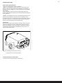
Figure 10: Circuit board
1. Electrical cable
2. Terminal for connection of elec-
trical cable
3. Cable grommet (x6)
4. Control panel cable
5. Modular contacts for connection
of control panel, sensor etc.
6. Sensor cable
7. Light cable (if connected)
8. Terminal for connection of
light (if connected)
9. Strain relief connector for
cables to modular contacts
(x2)
10. Strain relief connector for
electrical cable
11. Protection hose for RJ10
cables
INSTALLATION
Sauna heater installation
It is easiest to prepare for installation with the heater lying down.
To install the heater:
1. Lay the heater down with the front facing upwards.
2. Undo the screws and open the cover (see Figure 9).
Typical wall construction
Figure 9 Opening/closing the cover
8. Unscrew the fi rst two screws on the back of the heater and
screw one of the four brackets into place. Repeat the proce-
dure until all of the brackets are fi tted see Fig. 11.
NB: If all the screws on the back are unscrewed
simultaneously, the back plate may come loose.
For this reason, attach the four brackets to the
heater one at a time.
Figure 11: Attaching the brackets to the heater
9. Position the bracket screws according to the specifi ed dimen-
sioning see Fig. 12.

7
Unusual voltages/numbers of phases
Contact Tylö Customer Service before connecting to voltages or
numbers of phases that are not listed in the wiring diagram Figure
18.
External ON/OFF switch (option)
The external ON/OFF switch can be positioned anywhere outside
the sauna, not to exceed 75 feet from the heater, to avoid voltage
loss in the cable. Voltage loss aff ects the LED indicator for heater
status (if built-in and connected to the switch).
For further information, see instructions supplied with the control
panel.
Figure 13: Fitting the fragrance holder/air humidifi er
11. Hang the heater on the screws see Fig. 14.
Figure 14: Hang the heater up.
12. Lock the heater into place with the lock screw see Fig. 15.
Figure 15: Lock screw for bracket
13. Install the sensor on the wall see Fig 16. The thermistor wire
may also be passed through the wall. Seal any holes in the
wall behind the sensor, see Figure 17. The thermistor wire
may be extended outside the sauna using low voltage wire
(2-lead).
Figure 12: Dimensioning
1. 10.31 in
2. 6 in
3. 16.3 in
4. 8.11 in
10. Fit herb bowl/air humidifi er (see Fig. 13).
2
4
3
1
Figure 16: Installing the sensor
Figure 17: Seal any holes

8
Figure 18: Wiring diagram
1A. NTC Sensor
2A. Ext switch (External switch option-
al)
3A. N/A
4A. N/A
5A. N/A
6A. N/A
7A. N/A
8A. N/A
9A. Controls Elite
1B. NTC Sensor
2B. Ext switch (External switch optional)
3B. N/A
4B. N/A
5B. N/A
6B. N/A
7B. N/A
8B. Controls Pure
10. Heater
11. Terminal for connection of electrical cable
12. Control panel
(Elite - connect to positions 9A)
(Pure - connect to positions 8B)
13. Light/terminal for connection of light
14. Door contact (option)
15. External switch (option)
10
131415 12
11
13
RJ10 4P4C
3 x 14 AWG
RJ10 4P4C
RJ10 4P4C
ELITE PURE
max 75 feet
*
*
B
G
B4140
12
6789
34 5
1A 2A
6A 7A 8A 9A
3A 4A 5A
120 V~
14 AWG
Max. 6 Amp.
5,3-8,3 kW
208/240 V~
1B 2B 3B 4B
5B 6B
7B 8B
CONNECTION/WIRING DIAGRAM
TAB 208 V 1 Phase 240 V 1 Phase
Model Amperage
Amps
Output
kW
Wire Size
AWG
Amperage
Amps
Output
kW
Wire Size
AWG
Sense U 7 Pure/Elite 26 5,3 10 30 7,0 8
Sense U 8 Pure/Elite 30 6,3 8 35 8,3 8
Note: Heating elments do not change for voltage changes. The heater output will changed based on the voltage applied to heater.

9
SELF-INSPECTION OF THE INSTALLATION
To check the installation:
1. Turn power on at the Circuit Breaker Box.
2. Check that the control panel lights up.
3. Start the heater (see User Guide).
4. Check that all three tubular elements start to heat up (go
red).
Please keep these instructions!.
In the event of problems, please contact the retailer where you purchased
the equipment.
© This publication many not be reproduced, in part or in whole, without
the written permission of Tylö. Tylö reserves the right to make changes to
materials, construction and design.
1234Pin:
Pos 1A.
NTC
Pin 1:
Pin 2: NTC
Pin 3: NTC
Pin 4:
Pos 2A.
Ext sw
Pin 1:
Pin 2: LED
Pin 3: SW
Pin 4: 12 V
Pos 6A-9A.
4x RS485
Pin 1: A
Pin 2: B
Pin 3: 12 V
Pin 4: GND
Pos 5B-8B.
4x RS485
Pin 1: A
Pin 2: B
Pin 3: 12 V
Pin 4: GND
Pos 3A.
Door sw
Pin 1:
Pin 2: LED
Pin 3: SW
Pin 4: 12 V
Pos 4A.
Bim/NTC
Pin 1: Bim
Pin 2: NTC
Pin 3: NTC
Pin 4: Bim
Pos 1B.
NTC
Pin 1:
Pin 2: NTC
Pin 3: NTC
Pin 4:
Pos 2B.
Ext sw
Pin 1:
Pin 2: LED
Pin 3: SW
Pin 4: 12 V
Pos 3B.
Door sw
Pin 1:
Pin 2: LED
Pin 3: SW
Pin 4: 12 V
Pos 4B.
Bim/NTC
Pin 1: Bim
Pin 2: NTC
Pin 3: NTC
Pin 4: Bim
Pos 5A.
Addon (option)
1234Pin:
10
11
1A 2A
6A 7A 8A 9A
3A 4A 5A 1B 2B 3B 4B
5B 6B
7B 8B
ELITE PURE
Description of cabling/modular contacts
Figure 19: Modular contacts, description
ELITE
(Pos 1-4 and 6-9: RJ10, Pos 5: RJ45)
1A. NTC Sensor
2A. Ext switch (optional)
3A. N/A
4A. N/A
5A. N/A
6A. N/A
7A. N/A
8A. N/A
9A. Controls Elite
10. Modular plug (RJ10)
11. Modular contact (RJ10)
PURE
(Pos 1-8: RJ10)
1B. NTC Sensor
2B. Ext switch (External switch
optional)
3B. N/A
4B. N/A
5B. N/A
6B. N/A
7B. N/A
8B. Controls Pure
10. Modular plug (RJ10)
11. Modular contact (RJ10)
Table 3: Connecting components in modular contacts (maximum cable area for RJ10: 0.90 mm/0.20 mm², AWG24)
Connection of Pos Pin Comment
Temp. sensor (10kohm) 1 A/B 2-3 Must be NTC model.
External switch with no wire indicator 2 A/B 3-4 Both constant or impulse deactivation works.
External switch with wire indication 2 A/B 2-3-4 12VDC (max. 40mA).
NOTE! Crimp pliers are needed if changing modular
cabling, e.g. shortening wires.

10
14,8" 1,6"
375mm
17,0"
23,6"
431mm
600mm 41mm
206mm
8,11"
262mm
262mm
10,31"
262mm
10,31"
DIMENSIONS

11
USER GUIDE
GENERAL INFORMATION
Congratulations on your new sauna heater! Follow this user guide
to get the most from your purchase.
Wet and dry saunas are forms of bathing which originate way
back in history. A hot sauna is best enjoyed at temperatures be-
tween 145-190°F.
PRIOR TO USE
The fi rst time you use the heater
Fill the stone compartment
Fill the stone compartment around the heating elements from the
bottom to the top, to approx. 2” above the top front edge. Do not
press the stones into place. Capacity: Approx. 35 lb of stones.
Place the stones loosely to allow optimum air circulation. The tu-
bular heating elements must not be squeezed together or against
the side.
Sauna stones must:
• tolerate extreme heat and fl uctuations caused by water being
poured on them.
• be cleaned before use.
• must have an uneven surface, so that the water "clings" to
the stone surface and evaporates effi ciently.
• be between 1-1/2” to 2” in size to allow air circulation in the
stone compartment. This will increase the life of the tubular
elements.
Default settings
Using the control panel for the fi
rst time:
See instructions supplied with the control panel.
Prior to each use
Check the following
Check that:
• there are no foreign objects in the sauna cabin, on or in the
heater.
• the door and any windows to the sauna cabin are closed.
• that the sauna door opens outwards with a little pressure.
NB:
DANGER! Fragrant essences and similar prod-
ucts may ignite, if poured directly onto the
stones.
Figure 2: Positioning of the main power switch
1. Main power switch
Figure 1: Filling the stone compartment
1. Stone compartment
2. Side chambers
Turn on the heater to remove any new paint odors
To remove "new paint odor" from the heater:
Heat the sauna heater for about one hour. The water reservoir
does not need to be working.
A little smoke may appear.
NB: Always use dolerite stones (Tylö Sauna Stones)!
"Ordinary" stones may damage the heater.
Do not use ceramic stones. Ceramic stones may
damage the heater. The heater guarantee does not
cover damage caused by ceramic stones.
NB: Never place stones on top of the side air
chambers. This way will obstruct air circulation,
causing the unit to overheat and the cut-out switch
to activate.
1
2
NOTE! Do not use the sauna cabin for any purpose
other than taking saunas.
Turn on the main power switch
The main power switch is at the bottom of the heater.
Switch it on, if it is not already switched on (see Figure 2).
1

12
USE
The control panel in general
See instructions supplied with the control panel.
EXTERNAL ON/OFF SWITCH (OPTION)
External ON/OFF switch can be installed anywhere outside the
sauna. The switch is momentary pulse or constant activation.
The heater circuit automatically recognises which is used. Heater
status and faults on the door contact can be seen if the switch has
a built-in LED.
See instructions supplied with the control panel.
Figure 3: Other functions
1. Fragrance holder
2. Air humidifi er
To create a pleasant fragrance in the sauna, pour a few drops of
Tylö Sauna Fragrance into the water in the fragrance holder.
You can also mix a few drops of the sauna fragrance with water in
a sauna bucket and pour the water on fully heated stones. Use a
sauna ladle for pouring water on the hot stones.
Tylö Sauna Fragrance comes in diff erent variants and fragrances.
Go to www.tylo.com to see the full range.
To maintain a comfortable basic level of humidity in the sauna, fi ll
the built-in air humidifi er (see Fig. 3) with water before switching
on the sauna.
Fragrance holder
Figure 5: Cleaning the fragrance holder and air humidifi er
Check the stone compartment
Check the stone compartment at least once annually or as many
times per year as the heater is used per week.
Example: If the unit is used 3 times a week, check the stone
compartment 3 times per year.
How to check the stone compartment:
1. Remove all stones from the compartment.
2. Remove any small stones, gravel and limescale from the
compartment.
3. Put whole, undamaged stones back. Replace damaged sto-
nes with new ones as required (see Filling the stone compart-
ment, page 5).
Air humidifi er
DANGER! Fragrant essences etc. may ignite if
poured directly onto the stones.
1
2
DANGER! Do not pour water into the fragrance
holder once it has been heated up, as this can cause
boiling water to splash on the sauna occupants. Do
not stand or sit in front of the heater while water is
being poured into the fragrance holder, as hot water
can spray out suddenly.
Tip: Pour a few drops of diluted sauna fragrance into
the built-in air humidifi er.
MAINTENANCE
Cleaning the fragrance holder and air humidifi er
Clean the fragrance holder and air humidifi er as required.
To clean the fragrance holder and air humidifi er:
Remove the fragrance holder/air humidifi er and rinse them under
running water.
AFTER USE
Switch off the main power switch.
The main power switch is at the bottom of the heater.
Switch off here when the heater is not to be used for an extended
period (e.g. several weeks).
WARNING! If the stone compartment fi lls up with
gravel and small stones, the tubular element can be
damaged as a result of overheating, as air fl ow will
be insuffi cient.
1
Figure 4: Positioning of the main power switch

13
Figure 6: Resetting the temperature cut-out
1. Temperature cut-out sauna heater
1
Troubleshooting the control panel
See instructions supplied with the control panel.
TROUBLESHOOTING
Temperature Safety Switches
The heater's temperature protection devices:
• PCA - The temperature safety on the PCA in the heater is de-
signed to prevent components being damaged by overheating. If
the safety switch is triggered, an error code shows on the control
panel display.
If the overheating switch has activated, the heater cannot be
started again until the temperature has dropped down 68 degrees
(ºF) on the PCA.
• Heater - The temperature cut-out in the heater protects the com-
ponents and woodwork in the sauna from overheating. There
is a white reset button on the left side of the heater which must be
pressed in (see Fig. 9). If the heater safety switch has activated,
the button will feel stiff and will ‘click’ when reset.
Information!
When the overheating safety switches activate, always check the
cause of the problem. The life of the elements and PCA can be
adversely eff ected by each overheating. If systems continues to
overheat look at the following: Ventilation defi cient? Room vol-
ume? Internal heater fault?

14
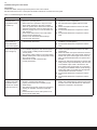
Symptom Possible cause Remedy
Heater element
in heater stone
compartment does
not warm up.
1. Temperature settings on control panel do not cor-
respond to operating status?
2. Water reservoir in operation? Only two of the
three heater elements in the stone compart-
ment can operate at the same time as the tank,
otherwise excessive current is drawn from the
electricity supply. This is not a fault outside nor-
mal operation.
3. Some of the heater fuses on the main switch-
board can have tripped out?
4. Resistor coil in the heater element faulty?
5. Internal heater PCB fault?
1. Set temperature to correspond to heater element
operation in stone compartment.
2. See the instructions supplied with the control
panel.
3. Check and replace/reset the fuses in the main
switchboard.
4. An authorised electrician is required to fi nd the
fault.
5. An authorised electrician is required to fi nd the
fault.
Lights in the sauna
do not come on
when switched on
at the control panel.
1. Is lighting connected via the heater?
2. Internal heater PCB fault?
1. Verify with authorized electrician who performed
installation of heater/lighting.
2. An authorized electrician is required to fi nd the
fault.
Heater does not
work, control panel
does not light up.
1. The main power switch is off ?
2. Circuit breaker tripped on main electical panel.
3. Loose contact in cabling between heater and
control panel?
4. The specifi c 12VDC output on one of the PCB's
RS485 modular jack to the control panel is faulty
due to short-circuit?
5. Transformer on PCB in heater faulty?
6. Control panel faulty?
1. Turn heater main power switch.
2. Check and replace/reset the fuses in the main
switchboard.
3. Switch off heater main power switch and connect
each/paired cable to the control panel. Switch on
heater main power switch again. If this does not
help, an authorized electrician is required to fi nd
the fault.
4. Requires an authorized electrician to fi nd the fault,
faulty 12VDC output is indicated by LED out next
to the RS485 output. Note: if the fault is in the
RJ10 cable to the control panel, do not click into
a working vacant RS485 outlet to avoid causing a
fault in that outlet. RJ10 cable must be replaced/
contacts fi tted in the event of a fault.
5. An authorized electrician is required to fi nd the
fault.
6. An authorized electrician is required to fi nd the
fault.
The fuses or circuit
breaker in the build-
ing breaker panel
trips as soon as the
heater is turned on.
1. There is a short-circuit at the heater GND. Can
be due to a faulty heater element?
2. Lighting connected to and controlled via the
heater faulty?
3. The heater has not been used for a long period,
causing an insulation fault in the heater ele-
ment?
4. Heater has had too much water poured on it?
5. Other internal heater fault?
1,2,3,4,5. Do not use the heater, switch off at main
heater main switchboard trip and disconnect heat-
er fuses on the main switchboard. An authorized
electrician is required to fi
nd the fault.
Troubleshooting the sauna heater
Information!
Contact the dealer during the guarantee period in the event of faults.
See the instructions for the control panel for details of faults not covered in this user guide.
Table 1: Troubleshooting the sauna heater

15
Please keep these instructions!.
In the event of problems, please contact the retailer where you purchased
the equipment.
© This publication many not be reproduced, in part or in whole, without
the written permission of Tylö. Tylö reserves the right to make changes to
materials, construction and design.
Figure 8: Symbol
The diff erent materials can be recycled as specifi ed by their
labelling.
You can help protect the environment by recycling or reusing the
spent appliances or the materials in them. Take the product to a
recycling centre without the sauna stones or the soapstone jacket
(if fi tted).
Contact your local authorities for details of your nearest recycling
centre.
ROHS (RESTRICTION OF HAZARDOUS SUBSTANCES)
Instructions for environmental protection:
Do not dispose of this product with the domestic refuse when no
longer in use. Take it to a recycling station for electrical and elec-
tronic equipment instead.
For further information, see the symbol on the product, manual or
packaging.
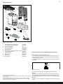
SPARE PARTS LIST
Figure 7: Spare parts 1
1. U8 Pure/Elite Tubular Elements 3001-924
U7 Pure/Elite Tubular element 3001-920
2. Stone compartment n/a
3. Circuit board Elite 9600 0068
Circuit board Pure 9600 0067
4. Terminal block 9600 0723
5. Sauna heater temperature safety switch 3119-607
6. Strain relief connector 9600 0554
7. On/Off Switch 9600 0040
8. On/off dial 9600 0132
9. Rock Guard 8019-541
10. NTC Sensor 9600 0219
3
7
8
9
10
4
6
5
2
1

16
GND MH
X1 X2 X3 X4 X5 X6 X7 X8 X9 X10 X11 X12 X13 X14 X15 X16
X17 X18
H3
H2
H1
H.Tank
Light
Aux 0
Sec/NTC
12345G
BB4140
f
e
d
c
b
a
6
5
4
3
2
1
L1 L2
GND
208-240V, 1-ph
FRONT
MIDDLE
BACK
GND GND
Switch
Circuit board
Type kW Amp Amp
208 V~ 240 V~
AWG AWG
Sense
Plus-U 7
Sense
Plus-U 8
5.3
6.3
7.0
8.3
26
30
-
-
10
8
-
-
-
-
30
35
-
-
8
8
Use only 194° F copper wire
Don´t forget to earth (ground)!
120 V~ N
13
42
High Limit Control
Heater
AWG 14
Max 6 Amp.
120 Volt Light input
(Separate from
Heater Power)
Output to light
HEATER WIRING DIAGRAM

17
NOTICE D'INSTALLATION........................................................ 18
AVANT L'INSTALLATION .................................................................... 18
Pièces ..................................................................................... 18
Exigences relatives à l'installation .......................................... 18
Outils d'installation .................................................................. 18
Planifi er l'installation ............................................................... 18
INSTALLATION .................................................................................... 21
Installation du poêle de sauna ................................................ 21
Interrupteur extérieur M/A (option) .......................................... 22
BRANCHEMENT/CÂBLAGE ....................................................... 23
Description des câblages/prises modulaires ................. 24
AUTOCONTRÔLE DE L'INSTALLATION................... 24
DIMENSIONS.......................................................................... 25
NOTICE D'UTILISATION............................................................ 26
INFORMATIONS GÉNÉRALES .......................................................... 26
AVANT L'UTILISATION ....................................................................... 26
Avant la première utilisation du poêle ..................................... 26
Avant chaque utilisation .......................................................... 26
UTILISATION ........................................................................................ 27
Généralités relatives au panneau de commande.................... 27
Autres fonctions....................................................................... 27
INTERRUPTEUR EXTÉRIEUR M/A (OPTION) ............................ 27
APRÈS L'UTILISATION ....................................................................... 27
Mettre l'appareil hors tension au moyen de l'interrupteur
principal................................................................... ................ 27
ENTRETIEN .......................................................................................... 27
Nettoyage du récipient à parfum et de l'humidifi cateur
................. 27
Contrôler le réservoir à pierres ............................................... 27
DÉPANNAGE ........................................................................................ 28
Dépannage du panneau de commande ................................. 28
Dépannage du poêle............................................................... 29
LISTE DES PIÈCES DE RECHANGE ................................................ 30
ROHS (RESTRICTION OF HAZARD US SUBSTANCES)
........................ 30
SCHÉMA DE CÂBLAGE DU POÊLE
....................................................... 31
AVERTISSEMENT !
• Risque de choc électrique - matériel à haute tension. Ce ma-
tériel ne contient aucune pièce réparable par l'utilisateur. Toute
installation et service de ce matériel doivent être eff ectués par
un personnel certifi é et qualifi é conformément aux codes locaux
et nationaux.
• Ne pas construire la cabine de sauna de manière à limiter la
circulation d'air à travers le fond du poêle.
• Empilez les pierres sans trop les serrer, au risque de déclen-
cher la protection thermique.
• Maintenez un dégagement minimum entre le poêle et les surfa-
ces en bois (bancs, cloisons latérales, grille de protection, etc.).
Les supports de montage sont fournis. Ils assurent un dégage-
ment adéquat par rapport au mur derrière le poêle.
• Utilisez uniquement du fi l de cuivre de la taille et du type indi-
qués dans le tableau des caractéristiques du poêle et dont la
température admissible est indiquée sur le boîtier de raccorde-
ment du poêle.
• Une rambarde ou un manteau de protection extérieur sont
nécessaires autour du poêle pour éviter les brûlures de contact
accidentel.
• Tous les poêles et les commandes doivent être mis à la terre
conformément au code NEC pour éviter tout choc électrique en
cas de panne de l'appareil.
• Ne pas monter de prises ou de boîtiers électriques à l'intérieur
d'une cabine de sauna.
• Ne pas placer de banquettes au-dessus du poêle.
• Pour usage domestique uniquement.
Conservez la présente notice d'utilisation !
En cas de problèmes, veuillez contacter le revendeur
où vous avez acheté le matériel.
© Cette publication ne peut être reproduite, en tout ou en partie, sans la
permission écrite de Tylö. Tylö se réserve le droit d'apporter des modifi ca-
tions dans les matériaux, dans la construction et dans la conception.
* L'hyperthermie survient lorsque la température interne du
corps atteint un niveau de plusieurs degrés au-dessus de la
température normale de 37° C (98,6° F). Les symptômes de
l'hypothermie comprennent une augmentation de la tempéra-
ture interne du corps, des étourdissements, la léthargie, la
somnolence et l'évanouissement. Les eff ets de l'hyperthermie
comprennent :
a) L’omission de percevoir la chaleur ;
b) Ne pas reconnaître la nécessité de sortir de la cabine ;
c) L’ignorance des dangers imminents ;
d) Des dommages fatals pour les femmes enceintes ;
e) L'incapacité physique de sortir de la cabine et
f) La perte de conscience
• La consommation d'alcool, de drogues ou de médicaments
est fortement déconseillée avant d'entrer dans une cabine de
sauna.
• Les femmes enceintes ou les personnes ayant une mauvaise
santé devront consulter leur médecin avant d'utiliser un sauna.
• Attention risques d'incendie : Ne pas utiliser la cabine de sauna
pour faire sécher des vêtements, des maillots de bain, etc. Ne
pas accrocher les serviettes au-dessus du poêle ou placer un
objet autre que les pierres fournies sur le poêle. Si un noircis-
sement de la paroi autour du poêle apparaît, cessez immédia-
tement l'utilisation de sauna.
• Examinez le sauna régulièrement pour l'entretien requis du
poêle, des commandes et des banquettes. Remplacer les sur-
faces en bois qui présentent des signes de détérioration.
• Le poêle devient extrêmement chaud pendant le fonctionne-
ment. Risques de brûlures en cas de contact avec les surfaces.
• Les enfants mineurs doivent être surveillés de manière adéqua-
te lorsqu'ils sont à proximité d'un sauna chaud ou en phase de
réchauff ement.
• Les systèmes de sécurité anti-incendie (sprinkler) utilisés à l'in-
térieur d'une cabine de sauna doivent être correctement réglés
en fonction des températures de la cabine.
• Ne pas verser de l’eau chlorée de piscine ou de spa sur le
poêle. L'utilisation excessive d'eau sur le poêle peut provoquer
des dommages et annuler la garantie.
• Cet équipement ne doit pas être utilisé par des personnes (y
compris des enfants) aux capacités physiques, sensorielles
ou mentales aff aiblies, ou n’ayant pas assez d’expérience et
de connaissance, à moins d’être surveillées ou d’avoir reçu
des instructions concernant l’utilisation de l’équipement, de la
part d’une personne responsable de leur sécurité. Les enfants
doivent être surveillés afi n de s’assurer qu’ils ne jouent pas
avec l’appareil.

18
NOTICE D'INSTALLATION
AVANT L'INSTALLATION
Pièces
Vérifi ez que tous les éléments suivants se trouvent bien dans
l'emballage :
Outils d'installation
Les outils et les matériaux suivants sont nécessaires pour l'instal-
lation et le branchement :
• niveau
• mètre-ruban
• perceuse électrique
• tournevis
Planifi er l'installation
Avant de commencer à installer votre poêle de sauna :
• Planifi er l'emplacement du poêle (voir Emplacement du poêle
: paragraphe Montage normal, page 19).
• Planifi er l'emplacement du panneau de commande (voir les
instructions ci-jointes pour le panneau de commande pour
l'emplacement adéquat).
• Planifi er l'emplacement de la sonde (voir Fig. 3, page 19).
• Positionner la bouche d'entrée d'air (voir le paragraphe
Emplacement de l'entrée d'air, page 20).
• Positionner la sortie d'air (voir le paragraphe Emplacement
de la sortie d'air, page 20).
• Planifi er l'installation électrique (voir le paragraphe Schéma
de raccordement/branchement, page 23).
2
8
67
15
5
1
34
9
10 11 12
13
14
16
Tableau 1 : Tension et volume du sauna
Modèle Tension Volume du
sauna min.
pi³
Volume du
sauna max.
pi³
Sense U 7 Pure/Elite
(SPU7)
208 V
240 V
175
175
265
320
Sense U 8 Pure/Elite
(SPU8)
208 V
240 V
250
250
360
440
Exigences relatives à l'installation
Pour garantir une utilisation sûre du poêle, vérifi ez que les
critères suivants sont respectés :
• Le câblage électrique doit être installé conformément au
code national d'électricité américain (NEC) et à tous les co-
des nationaux et locaux du pays où le système est installé.
• La taille du fusible (A) et la taille du câble d'alimentation
(AWG) doivent être adaptées au poêle (voir le paragraphe
intitulé Schéma de raccordement/branchement, Page 23.
• La ventilation du sauna doit se conformer aux instructions
de ce manuel (voir le paragraphe intitulé Emplacement de
l'entrée d'air, Page 20, le paragraphe intitulé Emplacement
de la sortie d'air, Page 20).
• L'emplacement du poêle, du panneau de commande et des
sondes doit se conformer aux instructions de ce manuel.
• La puissance du poêle (kW) doit être adaptée au volume du
sauna en m3 (pi³) (Voir tableau 1, page 18). Les volumes
minimum et maximum ne doivent pas être dépassés.
• REMARQUE : Un dispositif DDFT n’est pas requis par ETL.
Un DDFT peut être installé si requis par les codes locaux.
Cependant, les dispositifs DDFT ont tendance à se déclen-
cher de manière intempestive lors de l'utilisation du produit.
Fig. 1 : Éléments du poêle de sauna/panneau de commande
1. Poêle de sauna
2. Coupelle à herbes aromatiques/humidifi cateur
3. Supports x 4
4. Vis de fi xation B8x9,5 x 1 pièce
5. Plaques d’avertissement et de danger pour la cabine en
plusieurs langues
6. Vis B 4 x 6,5 x 6 pour plaques d’avertissement et de danger
7. Connecteurs x 3
8. Vis pour supports x 4
9. Capteur CTN, longueur de câble 4 m
10. Clips TC (3-5) x 10 pièces
11. Bouchon plastique 25 x 5 x 2 pièces
12. Vis B6x25 x 2 pièces
13. Vis B4x6,5 x 1 pièce
14. Capot de capteur
15. Protège-pierres
16. Gaine de protection Ø14x150 mm x 3 unites, pour les câbles
RJ10 (sonde, panneau de commande, contacteur de porte)
Contactez votre revendeur s'il manque une pièce quelconque.
La page est en cours de chargement...
La page est en cours de chargement...
La page est en cours de chargement...
La page est en cours de chargement...
La page est en cours de chargement...
La page est en cours de chargement...
La page est en cours de chargement...
La page est en cours de chargement...
La page est en cours de chargement...
La page est en cours de chargement...
La page est en cours de chargement...
La page est en cours de chargement...
La page est en cours de chargement...
-
 1
1
-
 2
2
-
 3
3
-
 4
4
-
 5
5
-
 6
6
-
 7
7
-
 8
8
-
 9
9
-
 10
10
-
 11
11
-
 12
12
-
 13
13
-
 14
14
-
 15
15
-
 16
16
-
 17
17
-
 18
18
-
 19
19
-
 20
20
-
 21
21
-
 22
22
-
 23
23
-
 24
24
-
 25
25
-
 26
26
-
 27
27
-
 28
28
-
 29
29
-
 30
30
-
 31
31
-
 32
32
-
 33
33


Tylö SENSE PLUS ELITE Sauna Heater Mode d'emploi
- Taper
- Mode d'emploi
dans d''autres langues
Documents connexes
-
Tylö 2900 Mode d'emploi
-
-
 TyloHelo Panacea 2525#hs_cos_wrapper_module_170083095099533 .icon-style--link .g-module-macros-icon { padding-left:8px; } #hs_cos_wrapper_module_170083095099533 .icon-style--link .g-module-macros-icon svg { fill:#C65622; } Le manuel du propriétaire
-

Autres documents
-
HARVIA HL Series Le manuel du propriétaire
-
-
Sentiotec Wave.Com4 Manuel utilisateur
-
-
HARVIA CX170-U1 Control Unit Le manuel du propriétaire
-
-
HARVIA KIP 8KW Manuel utilisateur
-
-
HELIOS easyControls KWL EC 220 D L Installation And Operating Instructions Manual
-
 Sawotec Nordex NEXT NR-90NB Manuel utilisateur
