Honeywell Home HE360 Manuel utilisateur
- Catégorie
- Déshumidificateurs
- Taper
- Manuel utilisateur

INSTALLATION INSTRUCTIONS
69-2629EF-11
HE360 Humidifier
M33322A

HE360 HUMIDIFIER
69-2629EF—11 2
WELCOME
To the comfortable world of humidified air. When you use your humidifier, notice that your skin is not as dry, and
that your scratchy throat and irritated nasal passages that aggravate allergies and asthma are steadily
improving.
You have also taken the first step in reducing the zapping you create when you walk on your carpet and then
touch your TV, computer, metal door knob or your pet. Your furniture and woodwork are also benefitting from the
difference that humidified air makes.
Congratulations! You have just made a great investment in improving the comfort of your home.
INSTALLATION
Preparing for the Installation
Be sure you have the required tools and accessories from Table 1 and in the Suggested Tools and Accessories
list before beginning the installation.
Included Accessories
Suggested Tools and Accessories
Tools required for installation include:
• Tin snip.
•Screwdriver.
• Adjustable or open-end wrench.
• Drill, punch or awl.
• Level.
• 18 gauge, two-strand thermostat wire, 20 ft (6.2 m).
• 1/4 in. (6.35 mm) OD feed water tubing, 20 ft (6.2 m).
• 1/2 in (12.7 mm) ID drain tubing, 10 ft (3.1 m).
• Code-compliant 1/4" water shut-off valve and fittings.
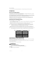
Determining Best Location for Humidifier
CAUTION
Temperature and Static Pressure Hazard.
Can cause property or equipment damage.
Locate humidifier where ambient temperature is between 32°F (0°C) and 160°F (71°C).
Do not install humidifier where freezing temperatures could occur.
Be sure supply plenum static pressure is no greater than 0.4 in. wc and water pressure is no greater than
124 psi.
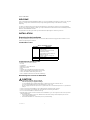
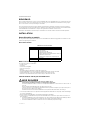
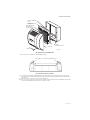
• Select a location for the humidifier on the supply (warm air stream) plenum. See Fig. 1.
• Select a location that cannot damage the air conditioner A-coil during installation.
• Do not locate the humidifier on the furnace body.
• Allow adequate clearance in front of and above the humidifier so you can easily remove the cover to perform
routine maintenance.
— Mount the humidifier at least 3 in. (78 mm) above the furnace body to allow adequate space for the
solenoid valve and drain line.
— Mount the humidifier in a conditioned space to prevent freezing.
Table 1. Included Accessories.
Quantity Accessory
1 bag Connecting and mounting hardware:
Wire nuts (4)
No. 8 sheet metal screws (18)
Drain tube clamp
Feed tube mounting clamps (6)
Brass inserts (2)
Plastic compression rings (2)
1Pressure switch
1 H6062 Humidistat

HE360 HUMIDIFIER
3 69-2629EF—11
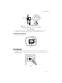
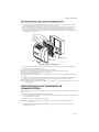
Fig. 1. Typical humidifier installation locations.
Selecting Water Supply Location
• Use either hard or soft water in the humidifier and either hot or cold water. The water flow rate, with the
humidifier running, is 3.5 gal/hr (13 liters/hr) to flush the pad and provide moisture for evaporation.
• Make sure the length of the 1/4" of feed water tubing is adequate to connect the water supply shut-off valve
with the humidifier solenoid valve.
Locating Closest Floor Drain
• Select location with access to a floor drain to provide drainage for air conditioner condensation and
humidifier drainage.
• If you do not have a drain available, we recommend that you install the Whole House Drum or Disk Humidifier.
Make sure the drain tubing is adequate to reach from the humidifier drain connection to the floor drain.
M12808C
HORIZONTAL
DOWN
FLO
LOWBOY
RETURN
RETURN
RETURN
HIGHBOY
RETURN

HE360 HUMIDIFIER
69-2629EF—11 4
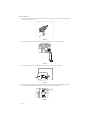
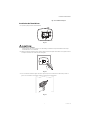
Selecting Location for Humidistat
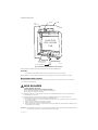
• Select a location for the humidistat on the return plenum or on the wall in the living space.
— Mounting on the return plenum is the easiest installation for the control wiring circuit.
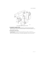
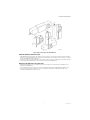
For return duct mounting, the humidistat should be mounted upstream from the humidifier or bypass so that it
is properly sensing the relative humidity of the living space. Locate the control at least 8 in. (203 mm) upstream
from the humidifier in the return air duct. (See Fig. 2.)
Fig. 2. Selecting duct location for humidistat.
Locating Closest 120V Electrical Outlet
• Select location with access to an outlet. If not available, contact an electrician to have one installed.
• Make sure that the humidifier cord is adequate to reach from the humidifier to the outlet.
• Make sure that the 20 ft (6.2m) of thermostat wire is adequate to reach from the humidifier solenoid, to the
pressure switch, to the humidistat.
Installing the Humidifier
WARNING
Hazardous Voltage
Can cause personal injury or equipment damage.
Do not cut or drill into any air conditioning or electrical accessory.
CAUTION
Sharp Edges Installation Hazard.
Can cause personal injury.
Wear gloves and safety glasses.
1. Turn off power to the air handing system at the circuit breaker.
2. Draw a level line on the plenum in the location chosen for the humidifier. (Leveling assures optimal
humidifier performance.)
3. Locate the template (form number 69-2641 included in the box).
4. Tape the template in position and trace around the template.
5. Remove the template and carefully cut the rectangular opening.
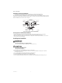
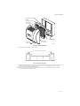
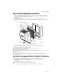
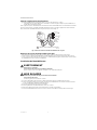
6. Disassemble the humidifier; remove the cover and take out the humidifier pad assembly. See Fig. 3
ALTERNATE
LOCATION
RETURN
AIR RETURN
AIR
6 IN (152 MM)
MINIMUM
15 IN (381 MM)
MINIMUM
BEST
LOCATION
RETURN
AIR DUCT
M34579B

HE360 HUMIDIFIER
5 69-2629EF—11
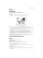
Fig. 3. Disassembling humidifier.
7. Position the securing clips as shown in Fig. 4.
Fig. 4. Position securing clips.
8. Make sure the humidifier housing is level, then position it in the opening so the plastic tabs are in place on
the lower sheet metal edge of the opening. Use pliers, as necessary, to flatten cut edges. See Fig. 5.
9. Push in securing clips until completely seated.
10. Drill holes and install the three sheet metal screws on the top of the humidifier housing. Secure the
housing with the three remaining screws.
M12809A
COVER
ASSEMBLY
HUMIDIFIER
PAD ASSEMBLY
FEED TUBE NOZZLE
WATER
DISTRIBUTION TRAY
HUMIDIFIER
HOUSING
THUMB
SCREW
M12813B
CLIP CLIP
TOP VIEW – HUMIDIFIER HOUSING

HE360 HUMIDIFIER
69-2629EF—11 6
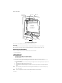
Fig. 5. Installing humidifier on duct.
11. Reinstall the humidifier pad assembly in the humidifier housing.
IMPORTANT
Be sure to reconnect the water feed tube and ensure that the tube is not pinched or kinked.
12. Hinge the cover in place and secure with the thumbscrew located at the bottom of the cover.
Connecting the Plumbing
Use hot or cold water and either hard or softened water in the humidifier.
1. Shut off the water.
CAUTION
Chemical Hazard.
Can cause personal injury or equipment damage.
Do not use any line connected to an air conditioner.
Do not use gas line.
2. Install the water shut-off valve in the water supply line at the location selected per local code.
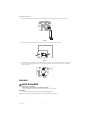
3. Use 1/4 in. (6 mm) copper or OD tubing and connect the shut-off valve to the inlet side of the solenoid
valve on the humidifier.
a. Insert the tubing into the solenoid valve fitting and support the valve while tightening the compression
nut.
b. Place the brass compression nut over the tubing.
c. Install brass insert into end of tubing.
d. Slide the plastic compression ring over the tubing. (Discard copper compression ring provided with
valve.)
NOTE: To prevent leaking, use plastic (Delrin) sleeve rings with plastic tubing. Use copper sleeve rings only
with copper tubing.
NOTE: Do not over-tighten the compression nut. Moderate tightness prevents leaking.
DUCT
LEVEL
SHEET METAL
SCREWS (4)
PLASTIC
TABS (2)
DRAIN TUBING M20204
OPENING
TO AIR DUCT

HE360 HUMIDIFIER
7 69-2629EF—11
e. Secure tubing with clamps provided.
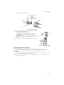
Fig. 6. Installing feed tubing.
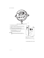
4. Connect a 1/2 in. (13 mm) drain tube to the humidifier drain fitting
and run to the floor drain (see Fig. 7).
a. Slide the drain clamp over the tubing.
b. Push the tubing over the drain nipple on the humidifier.
c. Hand-tighten the clamp around the tubing to secure the
humidifier drain.
d. Fasten the drain tubing (can use duct tape) along the route to
prevent movement and ensure downward slope for correct
drainage.
NOTE: Cut tubing to correct length so the tubing terminates at the drain.
Fig. 7. Installing the drain tubing.
Installing the Pressure Switch
NOTE: When a Honeywell Home IAQ thermostat controls the humidifier, the pressure switch is optional
because the thermostat can be configured to only run the humidifier with a call for heat.
IMPORTANT
Do not install the switch in an area where temperature exceeds rating of -40°F to 190°F (-40°C to 88°C).
1. Disconnect power from the humidifier before installing.
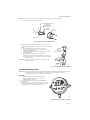
2. Mount the switch vertically with pressure connectors facing down, using provided self-tapping screws to
secure the switch to the duct.
M39203
BRASS COMPRESSION NUT
PLASTIC
COMPRESSION
RING
BRASS INSERT
SOLENOID
VALVE
M20177A

HE360 HUMIDIFIER
69-2629EF—11 8
Fig. 8. Pressure switch—oriented vertically.
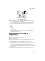
3. The return duct is recommended, however the switch can also
be mounted to the supply duct.
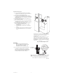
4. Cut a 3/4-in. diameter hole in the duct within 10 feet of the
switch to ensure the provided tubing reaches the pressure tap
elbow.
5. Insert the black rubber gasket into the duct hole.
6. Connect the tubing to the tubing fitting elbow and insert the
tubing fitting elbow into the black rubber gasket.
7. Connect the other end of the tubing to the applicable pressure
connection on the switch.
e. Black connection if installed on the supply
f. Grey connection if installed on the return
g. Both grey and black if installed on both
IMPORTANT
With low-speed airflow or variable speed systems it is
recommended to run tubing to both the supply and return
ducts.
Fig. 9. Mounting the pressure switch.
M27300
M27303A
A
B
SUPPLY DUCT INSTALL - AIR LINE ONLY TO TAP A,
CONNECTED TO THE + PORT ON THE AIR FLOW SWITCH
RETURN DUCT INSTALL - AIR LINE ONLY TO TAP B,
CONNECTED TO THE – PORT ON THE AIR FLOW SWITCH
SUPPLY/RETURN DUCT INSTALL - AIR LINE CONNECTED
TO BOTH THE + AND – PORTS ON THE AIR FLOW SWITCH

HE360 HUMIDIFIER
9 69-2629EF—11
Fig. 10. Install tubing.
8. You may cut the tubing to fit the connection length between the elbow fitting and switch. It is also
recommended to secure the hose to existing structures to avoid accidental disconnection.
Installing the Humidistat
1. Separate wallplate from humidistat.
Fig. 11.
CAUTION
Electrical Hazard
Can cause electrical shock or equipment damage. Disconnect power before beginning installation.
2. Mark the duct-tube hole. Hold the wallplate up to the desired location on the duct and make a mark inside
the duct tube hole.
Fig. 12.
M27304A
INSIDE
OF DUCT
CONNECT TUBING TO + CONNECTION IF PRESSURE TAP IS
MOUNTED TO SUPPLY DUCT. CONNECT TO – IF PRESSURE
TAP IS MOUNTED TO RETURN DUCT.
1
1
M34565A
Setting
Light
Next Auto
System
%
Replace BattReplace Batt
Inside
%
HUMIDITY BOOST
PULL HERE
M34580A

HE360 HUMIDIFIER
69-2629EF—11 10
3. Drill the duct-tube hole. Find your mark and drill a 1/2 in. hole in the duct. This is where the duct tube will
be inserted to capture air.
Fig. 13.
4. Insert the duct tube. Insert the duct tube through the wallplate before securing to the duct.
Fig. 14.
5. Secure the wallplate. Secure the wallplate to the duct with sheet metal screws (provided).
Fig. 15.
6. Run wires through the back plate. Run wires through the top or bottom channel on the back plate when
ductmounted. If installing like a thermostat on a wall, run the wires through the back.
Fig. 16.
M34581C
M34671B
M34582B
M34610B
RUN WIRES
THROUGH THE
TOP OR BOTTOM
CHANNEL
C
R
U
U
S
S

HE360 HUMIDIFIER
11 69-2629EF—11
WIRING
CAUTION
Hazardous Voltage.
Can cause personal injury or equipment damage.
Disconnect power supply before installing or servicing equipment.
IMPORTANT
All wiring must comply with applicable local code, ordinances and regulations.
Wire the humidifier solenoid valve, pressure switch, and humidistat. See Fig. 17.
Fig. 17. Wiring the controls.
NOTE: When a Honeywell Home IAQ thermostat controls the humidifier, the pressure switch is optional
because the thermostat can be configured to only run the humidifier with a call for heat.
1. Run two, two-strand thermostat wire bundles from the humidifier to the humidistat. Run one, two-strand
thermostat wire bundle from the humidistat to the pressure switch.
2. Cut lengths of thermostat wire to reach between components, leaving adequate wire at both ends for
connections.
3. At the humidifier, connect the two red wires to the red and white wires from wire bundle 1.
4. At the humidifier, connect the two yellow wires to the red and white wires of wire bundle 2.
5. At the humidistat, connect the red and white wires from bundle 1 to R and C (polarity doesn't matter).
6. At the humidistat, connect the red wire from bundle 2 to the upper U terminal.
7. At the humidistat, wire-hut the white wire from bundle 2 to the white wire in bundle 3 (going to the
pressure switch).
8. At the humidistat, wire the red wire from bundle 3 to the lower U on the humidistat.
9. At the pressure switch, connect the red and white wires from bundle 3 to the C and NO pressure switch
terminals. (NC terminal is not used).
TESTING HUMIDIFIER OPERATION
Checklist
Humidifier is level.
Control wiring was reviewed using circuit diagram.
Humidifier is plugged in.
Feed line has no kinks.
Drain line slopes continuously down and ends at floor drain.
Water hose inside humidifier is connected to PerfectFlow™ water distribution tray.
After installation use the following steps to check the humidifier operation:
1. Turn on the power and the water supply
2. Turn the H6062 Humidistat all the way up and turn on the heat by setting the thermostat to 10 ºF (6 ºC)
above room temperature.
IMPORTANT
The furnace blower must be on to activate the humidifier.
3. Make sure that water is flowing out of the drain hose. If water does not flow, see Troubleshooting Your
Humidifier section.
4. Check for leaks.
M39012
AIR
PRESSURE
SWITCH
C
R
U
U
S
S
24 VAC (CONSTANT)
OUTDOOR SENSOR
1
WIRE OUTDOOR SENSOR TO THE S TERMINALS.
1
YELLOW
WIRES
RED
WIRES

HE360 HUMIDIFIER
69-2629EF—11 12
5. Reset the thermostat and H6062 Humidistat to a comfortable setting for automatic operation.
OPERATION
How Your Humidifier Works
Your humidifier uses the principle that vapor (evaporated water) is created when warm air blows over a water-
soaked area. As the vapor circulates, the relative humidity rises.
Your humidity control monitors the relative humidity and activates the humidifier accordingly. The humidifier
has a water supply that dispenses water evenly over a humidifier pad. The warm dry air, from the furnace, passes
over the humidifier pad and picks up the moist air to circulate it throughout your home.
Humidified air feels warmer and more comfortable so you may be able to lower your thermostat heating
setpoint, which saves money on your heating fuel bills. The end result is that your humidifier gives you a
comfortable environment that is also energy efficient.
Controlling Your Humidity Settings
Your H6062 Humidistat controls your humidifier.
• Choose the humidity control setting using the combination of relative humidity/outdoor temperature setting
scale on your humidity control dial.
• When the outdoor sensor is used, the H6062 will optimize the humidity level while reducing moisture
condensation on the windows. See the H6062 instructions for settings and adjustments.
NOTE: If the outdoor sensor is not used with H6062, as the outside temperature drops, a lower humidity
setting is recommended to accommodate dewpoint effects. These settings should reduce the
accumulation of moisture and ice on windows and other areas of the home.
• Adjust the humidity control setting to adjust for indoor activities such as cooking, showering and clothes
drying, which can cause excessive levels of humidity that can accumulate moisture on your windows.
NOTE: If these activities persist for more than a few hours, set the humidity control to the lowest setting to turn
off the humidifier. If the condition does not improve, ventilate your home to remove the moisture.
MAINTAINING YOUR HUMIDIFIER
A regular maintenance program prolongs the life of your humidifier and makes your home more comfortable.
The frequency of cleaning depends on the condition of your water.
You can use either hard or soft water in your humidifier, but hard water mineral deposits are more difficult to
clean than soft water deposits.
Use the following procedure to clean your humidifier.
WARNING
Serious Personal Injury Hazard.
Can cause electrical shock and injury from moving parts.
Disconnect power and shut off water supply before removing cover.
IMPORTANT
Never oil any part of the humidifier.
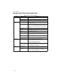
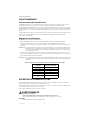
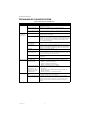
Table 2. Setting Your Humidistat when outdoor sensor is not used.
When Outside
Temperature is:
Use This Control
Setting:
-20°F (-29°C) 15
-10°F (-23°C) 20
0°F (-18°C) 25
+10°F (-12°C) 30
+20°F (-7°C) 35
Above 20°F (-7°C) 40

HE360 HUMIDIFIER
13 69-2629EF—11
Every 1 to 3 Months (Depending on Water Quality)
1. Disconnect the power and turn off the humidifier water supply.
2. Remove the humidifier cover by unplugging the connector and loosening the thumb screw. Grasp the
cover near the bottom and pull toward you. See Fig. 18.
3. Remove the humidifier pad assembly from the humidifier by grasping the top of the tray and pulling it
toward you.
4. Lift the tray off the pad.
5. Gently pinch the water nozzle catches inward until you can lift the water nozzle off the tray.
6. Carefully remove any mineral deposits from the tray and frame. Be sure the frame drain hole has nothing
blocking it.
Fig. 18. Cleaning your humidifier.
7. Disconnect the drain hose from the drain fitting on the bottom of the humidifier housing.
8. Clean the drain fitting, if necessary.
9. Bend the drain hose to loosen any mineral deposits.
10. Flush the drain hose with pressurized water (a running tap) to clean the hose.
11. Reattach the drain hose to the drain fitting.
12. Snap the water nozzle back on the tray.
13. Be sure the marked end of the pad is facing up. Place the tray on the new pad.
14. Place the humidifier pad assembly in the humidifier housing. Be sure the water feed tube is placed in the
guide slots.
15. Replace the humidifier cover.
16. Verify the humidifier operation by following the steps in the Checking Your Humidifier for Correct
Operation section.
CHECKING YOUR HUMIDIFIER FOR CORRECT OPERATION
After winter startup or servicing, use the following steps to check your humidifier operation:
1. Turn on the humidifier power and water supply.
2. Turn the humidistat to its highest setting and set the thermostat to 10°F (6°C) above the room
temperature.
3. Observe that water is flowing out of the drain hose.
NOTE: The furnace blower must be running to activate the humidifier.
4. Reset the thermostat and humidistat to a comfortable setting for automatic operation.
M12809A
COVER
ASSEMBLY
HUMIDIFIER
PAD ASSEMBLY
FEED TUBE NOZZLE
WATER
DISTRIBUTION TRAY
HUMIDIFIER
HOUSING
THUMB
SCREW

HE360 HUMIDIFIER
69-2629EF—11 14
TROUBLESHOOTING YOUR HUMIDIFIER
Table 3. Troubleshooting Humidifier.
Problem What to look for What to do
Water leakage Leaking joints. Shut off water.
Tighten connections.
Brass tubing inserts Verify that brass tubing inserts are used.
Saddle valve leaking. If a saddle valve is used as the shut-off valve, verify rubber
pad is installed on saddle valve.
No water to
drain. Electrical Verify control circuit wiring.
Check all connections.
Humidistat Turn the humidistat up all the way. If "Humidity Boost"
appears on the screen the H6062 is calling for humidity. If it
does not, the installer may not have enabled boost and it is
possible very cold outside temperatures could be restricting
humidity.
Humidifier power Verify that outlet has power.
Solenoid After verifying other wiring components, turn on furnace fan,
turn humidistat up and down, and listen for solenoid to click.
Plumbing Verify plumbing connections.
Check for kinks.
Shut-off valve Verify shut-off valve is turned on. If a saddle valve is used,
verify that needle pierces water line and then backs out
needle to open valve.
Humidifier Remove cover and verify that water flows into distribution
tray.
Drain tubing Verify no obstructions.
Low humidity Furnace blower not
operating. •Reset circuit breaker or check for blown fuse.
•Check that the furnace power is on.
•Check all external wiring connections.
•Check the humidity control setting.
•Call a professional heating contractor.
Rapid air changes.
Drafts (cold air is dry
and is an added load to
the humidifier).
•Keep doors and windows closed.
•Close fireplace damper when not in use.
•Keep exhaust fan running time to a minimum.
•Seal around doors and windows.
High humidity Condensation on
walls. •Turn off humidity control and water until condensation is
completely evaporated.
Heavy condensation
on windows. •The H6062 can be set for frost control if outdoor sensor is
used. If already set for window protection. If frost
protection is enabled, and you still get condensation,
lower the setting on the H6062.

HE360 HUMIDIFIER
15 69-2629EF—11
LIMITED ONE-YEAR WARRANTY
Resideo warrants this product to be free from defects in workmanship or materials, under normal use and
service, for a period of one (1) years from the date of first purchase by the original purchaser. If at any time
during the warranty period the product is determined to be defective due to workmanship or materials, Resideo
shall repair or replace it (at Resideo's option).
If the product is defective,
(i) return it, with a bill of sale or other dated proof of purchase, to the place from which you purchased it; or
(ii) call Resideo Customer Care at 1-800-468-1502. Customer Care will make the determination whether the
product should be returned to the following address: Resideo Return Goods, 1985 Douglas Dr. N., Golden Valley,
MN 55422, or whether a replacement product can be sent to you.
This warranty does not cover removal or reinstallation costs. This warranty shall not apply if it is shown by
Resideo that the defect was caused by damage which occurred while the product was in the possession of a
consumer.
Resideo's sole responsibility shall be to repair or replace the product within the terms stated above. RESIDEO
SHALL NOT BE LIABLE FOR ANY LOSS OR DAMAGE OF ANY KIND, INCLUDING ANY INCIDENTAL OR
CONSEQUENTIAL DAMAGES RESULTING, DIRECTLY OR INDIRECTLY, FROM ANY BREACH OF ANY
WARRANTY, EXPRESS OR IMPLIED, OR ANY OTHER FAILURE OF THIS PRODUCT.
Some states do not allow the exclusion or limitation of incidental or consequential damages, so this limitation
may not apply to you.
THIS WARRANTY IS THE ONLY EXPRESS WARRANTY RESIDEO MAKES ON THIS PRODUCT. THE DURATION OF
ANY IMPLIED WARRANTIES, INCLUDING THE WARRANTIES OF MERCHANTABILITY AND FITNESS FOR A
PARTICULAR PURPOSE, IS HEREBY LIMITED TO THE ONE YEAR DURATION OF THIS WARRANTY. Some states
do not allow limitations on how long an implied warranty lasts, so the above limitation may not apply to you.
This warranty gives you specific legal rights, and you may have other rights which vary from state to state. If you
have any questions concerning this warranty, please write Resideo Customer Care, 1985 Douglas Dr, Golden
Valley, MN 55422 or call 1-800-468-1502.

HE360 HUMIDIFIER
© 2022 Resideo Technologies, Inc. All rights reserved.
The Honeywell Home trademark is used under license from Honeywell International, Inc. This product is manufactured by Resideo Technologies, Inc. and its affiliates.
Tous droits réservés. La marque de commerce Honeywell Home est utilisée avec l’autorisation d’Honeywell International, Inc.
Ce produit est fabriqué par Resideo Technologies, Inc. et ses sociétés affiliées.
www.resideo.com
Resideo Technologies, Inc.
1985 Douglas Drive North, Golden Valley, MN 55422
1-800-468-1502
69-2629EF—11 M.S. Rev. 09-22 | Printed in United States

NOTICE D'INSTALLATION
Humidificateur HE360
M33322A

HUMIDIFICATEUR HE360
69-2629EF—11 2
BIENVENUE…
dans un environnement tout confort, où l'air est humidifié. Avec votre humidificateur, vous constaterez que votre
peau sera moins sèche. Vous remarquerez aussi, de jour en jour, une diminution de l'irritation de votre gorge et
de vos voies nasales causée par les allergies et l'asthme.
Vous venez de faire le premier pas pour éliminer le phénomène de décharge électrique lorsque vous marchez
sur une moquette, puis touchez le téléviseur, l'ordinateur, une poignée de porte en métal ou votre animal. Enfin,
l'air humidifié fait toute la différence car il préserve également les meubles et les boiseries.
Félicitations ! En rendant votre maison plus confortable, vous venez de réaliser un investissement important.
INSTALLATION
Avant d'installer ce produit
Be sure you have the required tools and accessories from Tableau 1 and in the Suggested Tools and Accessories
list before beginning the installation.
Accessoires fournis
Outils et accessoires suggérés
Les outils nécessaires à l’installation :
• Cisailles à tôle.
•Tournevis.
• Clé ouverte ou réglable.
• Perceuse ou poinçon.
•Niveau.
• Fil thermostatique à deux brins, calibre 18, 6,2 m (20 pi).
• Tuyaux d’alimentation en eau, 6,2 m (20 pi), diamètre extérieur de 1/4 po (6,35 mm)
• Tuyaux de drainage, 3,1 m (10 pi), diamètre intérieur de 12,7 mm (1/2 po)
• Vanne de sectionnement d’eau et raccords de 1/4 po conformes aux codes.
Choix du meilleur endroit pour l'humidificateur
MISE EN GARDE
Risques liés à une température ou une pression statique élevée.
Peut causer des dommages matériels ou endommager l'équipement.
Installer l'humidificateur dans un endroit où la température ambiante se situe entre 0° C (32 °F) et 71 °C
(160 °F).
Ne pas installer l'humidificateur dans un endroit exposé au gel.
S'assurer que la pression statique de l'alimentation dans le plenum ne dépasse pas 0,4 po C.E. et que la
pression de l'eau ne dépasse pas 124 psi.
Déterminer l'endroit où installer l'humidificateur sur le plenum (flux d'air chaud). Voir la Fig. 1.
• S'assurer qu'à l'endroit choisi, le serpentin en A de l'appareil de climatisation ne risque pas d'être endommagé
au cours de l'installation.
• Ne pas installer l'humidificateur sur le boîtier de l'appareil de chauffage.
• S'assurer qu'il y a suffisamment d'espace devant l'humidificateur et au-dessus pour enlever le couvercle et
faire l'entretien.
— Installer l'humidificateur au moins 78 mm (3 po) au-dessus du boîtier de l'appareil de chauffage afin de
laisser un espace suffisant pour le montage de l'électrovanne et du tuyau de vidange.
— Installer l'humidificateur dans un endroit où l'air est conditionné pour prévenir le gel.
Tableau 1. Accessoires fournis.
Quantité Accessoires
1 sac Quincaillerie de raccordement et de fixation :
Serre-fils (4)
Vis à tôle no 8 (18)
Bride de tuyau de vidange
Brides de fixation du tuyau d'arrivée d'eau (6)
Garnitures en laiton (2)
Anneaux de compression en plastique (2)
1Pressostat
1 Humidistat H6062

HUMIDIFICATEUR HE360
3 69-2629EF—11
.
Fig. 1. Emplacements types de l'humidificateur.
Choix de l'endroit d'arrivée d'eau
• L'humidificateur fonctionne avec de l'eau dure ou de l'eau douce. L'eau peut être chaude ou froide. Le débit
d'eau nécessaire pour imbiber l'écran évaporateur et transformer l'eau en vapeur est de 13 litres/h (3,5 gal/h)
lorsque l'humidificateur est en marche.
• Assurez-vous que la longueur du tuyau d’alimentation en eau de 1/4 po est suffisante pour relier la vanne de
sectionnement de l’alimentation en eau à la valve solénoïde de l’humidificateur.
Repérage du siphon de sol le plus près
• Choisir un endroit avec accès au siphon de sol pour l'évacuation de la condensation du climatiseur et la
vidange de l'humidificateur.
• Si vous ne disposez pas d’un drain, nous vous recommandons d’installer l’humidificateur à tambour ou à
disque pour toute la maison. Assurez-vous que les tuyaux de drainage sont suffisamment longs pour
raccorder l’humidificateur à l’avaloir de sol.
MF12808
HORIZONTAL
CAISSONS
JUXTAPOSÉS
RETOUR
RETOUR
RETOUR
CAISSONS
SUPERPOSÉS
RETOUR
DÉBIT
DESCENDANT

HUMIDIFICATEUR HE360
69-2629EF—11 4
Choix de l’emplacement de l'humidistat
• Installer l'humidistat dans le plenum de reprise ou sur le mur d'une pièce occupée.
— L'installation du circuit de câblage des commandes est beaucoup plus simple lorsque l'humidistat est
installé dans le plenum de reprise.
Dans la gaine de reprise, l'humidistat doit être installé en amont de l'humidificateur ou en dérivation de manière
qu'il puisse détecter avec exactitude l'humidité relative dans la pièce. Installer l'appareil à au moins 203 mm
(8 po) en amont de l'humidificateur dans la gaine de reprise. (Voir la Fig. 2.)
Fig. 2. Choix de l'endroit où installer l'humidistat dans la gaine.
Repérage de la prise électrique 120 V la plus près
• Choisir un endroit près d'une prise. S'il n'y a pas de prise, en faire installer une par un électricien.
• S'assurer que le cordon de l'humidificateur est suffisamment long et qu'il peut être branché dans la prise.
• S'assurer que le fil de thermostat de 6,2 m (20 pi) est suffisamment long pour être branché de l'électrovanne
de l'humidificateur à Pressostat et à l'humidistat.
Installation de l'humidificateur
AVERTISSEMENT
Risque de choc électrique.
Peut causer des blessures ou des dommages matériels.
Ne pas couper ou percer un appareil électrique ou de conditionnement d'air.
MISE EN GARDE
Arêtes vives présentant un danger au moment de l'installation.
Peut causer des blessures.
Porter des gants et des lunettes de sécurité.
1. Couper l'alimentation du système de conditionnement de l'air dans le tableau à disjoncteurs.
2. Tracer une ligne de niveau sur le plenum, à l'endroit où l'humidificateur sera installé. (La mise au niveau
assure le rendement optimal de l'humi-dificateur.)
3. Prendre le gabarit dans la boîte (pièce 69-2641).
4. Fixer le gabarit avec du ruban adhésif et en tracer le contour.
5. Enlever le gabarit et découper soigneusement une ouverture rectangulaire.
6. Démonter l'humidificateur, enlever le couvercle et retirer l'ensemble écran évaporateur. Voir la Fig. 3
MF39012
CONTACTEUR
BASSE
PRESSION
C
R
U
U
S
S
1
CÂBLEZ LE CAPTEUR EXTÉRIEUR AUX BORNES S.
1
FILS
JAUNES
FILS
ROUGES
24 VCA (CONSTANT)
CAPTEUR EXTÉRIEUR
La page est en cours de chargement...
La page est en cours de chargement...
La page est en cours de chargement...
La page est en cours de chargement...
La page est en cours de chargement...
La page est en cours de chargement...
La page est en cours de chargement...
La page est en cours de chargement...
La page est en cours de chargement...
La page est en cours de chargement...
La page est en cours de chargement...
La page est en cours de chargement...
-
 1
1
-
 2
2
-
 3
3
-
 4
4
-
 5
5
-
 6
6
-
 7
7
-
 8
8
-
 9
9
-
 10
10
-
 11
11
-
 12
12
-
 13
13
-
 14
14
-
 15
15
-
 16
16
-
 17
17
-
 18
18
-
 19
19
-
 20
20
-
 21
21
-
 22
22
-
 23
23
-
 24
24
-
 25
25
-
 26
26
-
 27
27
-
 28
28
-
 29
29
-
 30
30
-
 31
31
-
 32
32


Honeywell Home HE360 Manuel utilisateur
- Catégorie
- Déshumidificateurs
- Taper
- Manuel utilisateur
dans d''autres langues
- English: Honeywell Home HE360 User manual
Documents connexes
Autres documents
-
Honeywell HE105 Whole Home Bypass Humidifier Guide d'installation
-
Trane EHUMD200ABM00B Manuel utilisateur
-
Honeywell HE220 Manuel utilisateur
-
Honeywell HE120 Manuel utilisateur
-
Reliance PULSE FLOW-THRU Le manuel du propriétaire
-
GeneralAire SL-16 Guide d'installation
-
Honeywell TrueEASE Manuel utilisateur
-
-
General 1137R Le manuel du propriétaire
-
General SL-16 Le manuel du propriétaire