HUANUO HNDSK4 Guide d'installation
- Catégorie
- Supports de bureau à panneau plat
- Taper
- Guide d'installation

HNDSK4
(US/CA) 1-800-556-0533
(UK) 44-808-196-3874 [email protected]
www.huanuo.com
WWW.
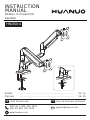
INSTRUCTION
MANUAL
MANUEL D'UTILISATION
Rev00(B)
Desk Monitor Arm
EN Bras de Moniteur de Bureau
FR
English -------------------------------------- 02-15
Français -------------------------------------- 16-29

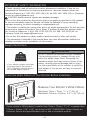
IMPORTANT SAFETY INFORMATION
Weight Restrictions
Check the VESA Pattern of Your Monitor Before Installation
• Please carefully read all instructions before attempting installation. If you do not
understand the instructions or have any questions or concerns, please contact our
Technical Support at 1-800-556-0533 (US/CA), 44-808-196-3874 (UK) or Customer
Service at [email protected].
CAUTION: Avoid potential injuries and property damage!
• Do not use this product for any purpose that is not explicitly specified in this manual.
Do not exceed weight capacity. We are not liable for damage or injury caused by
improper mounting, incorrect assembly or inappropriate use.
• This product contains gas spring arms which are under high pressure. Do not puncture
these arms or expose the arms to fire or flame. If product is defective, please contact
our Technical Support at 1-800-556-0533 (US/CA), 44-808-196-3874 (UK) or
Customer Service at [email protected].
• Do not use this product on desks made of particle board or other soft woods.
• The information contained in this manual does not cover all possible conditions or
variables in relation to the installation of this product.
If your monitor's VESA pattern is smaller than 75mm x 75mm / 3″ x 3″ or greater than
100mm x 100mm / 3.9″ x 3.9″, this mount is NOT COMPATIBLE. Please contact our
Customer Service at [email protected] to find a compatible product.
Minimum: 75mm x 75mm / 3″ x 3″ (W x H)
Maximum: 100mm x 100mm / 3.9″ x 3.9″ (W x H)
Measure Your Monitor's VESA Pattern:
MAX: 100mm/3.9″
MAX: 100mm/3.9″
If your monitor weighs more than
the weight above, the mount is
NOT compatible. Monitor should
not exceed weight capacity.
WARNING
DO NOT exceed the maximum weight indicated.
This mounting system is intended for use only
within the weight range listed. Exceeding the
maximum weight limit may result in failure of the
mount, causing potential damage and/or injury.
It is the responsibility of the installer to verify the
total weight of the monitor and any accessories
attached.
2-10kg
(4.4-22 lbs)
02 03 04 05 06 07 08 09 10 11 12 13 14 15

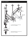
Product Features
270°270°
270°270°
360°360°
180°180°360°360°
180°180°
+90°/-45°
360°
Grommet Mounting for grommet bolt
0.39-2.56″ (10-65mm)
C-Clamp Mounting for table edge
0.39-3.15″ (10-80mm)
02 03 04 05 06 07 08 09 10 11 12 13 14 15

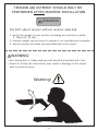
DO NOT adjust tension without monitor attached.
1. Verify the weight of your monitor (including accessories) is within
2-10kg (4.4-22 lbs).
2. Monitor weight can be found in manual or on manufacturer's website.
3. Ensure monitor has been securely attached to the mount.
TENSION ADJUSTMENT SHOULD ONLY BE
PERFORMED AFTER MONITOR INSTALLATION
Attention
WARNING:
• Gas Spring Arm is under pressure and should be handled with care.
• Failure to follow the instructions may result in damage to the mount
and/or personal injury.
Warning!
02 03 04 05 06 07 08 09 10 11 12 13 14 15

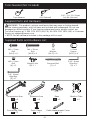
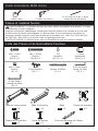
Supplied Parts and Hardware List
5/32'' (4mm)
Allen Key
[D] × 1
M4 × 12mm
Bolt
[M-A] × 8
D4
Washer
[M-C] × 8
M4 × 30mm
Bolt
[M-B] × 8
L13mm
Spacer
[M-D] × 8
1/4'' (6mm)
Allen Key
[E] × 1
M6 x 10mm
Bolt
[A] × 2 Butterfly Nut
[B] × 1
Grommet Bolt
[C] × 1
01 × 2
Compression Arm 02 × 2
Extension Arm 03 × 1
Base
04 × 2
Monitor Plate
05 × 1
Connecting Plate 06 × 1
Desk Clamp 07 × 2
Cable Management Cover
Supplied Parts and Hardware
Tools Needed (Not lncluded)
WARNING: This product contains small parts that may pose a choking hazard.
Before starting assembly, verify all parts are included and undamaged. Do not use
damaged or defective parts. lf you require replacement parts, please contact our
Technical Support at 1-800-556-0533 (US/CA), 44-808-196-3874 (UK) or Customer
Service at [email protected].
• NOTE: Not all hardware included in this package will be used.
Tape Measure Drill (Optional) 7/16''-7/8'' (11-22mm)
Drill Bit (Optional)
02 03 04 05 06 07 08 09 10 11 12 13 14 15

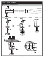
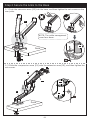
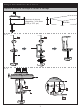
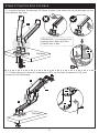
Option A: For Clamp Mounting
Step 1 Install the Base
Compatible desk thickness:
0.39''-3.15'' (10-80mm)
Desk
03
06
05
D
A
EE
D
A
03
A-1
A-2
02 03 04 05 06 07 08 09 10 11 12 13 14 15

Option B: For Grommet Mounting
B-2 Remove the lock plate [06a] and keep it for use in Step B-3.
03
C
Desk
Compatible desk thickness:
0.39-2.56″ (10-65mm)
Desk
06
E
06a
B-1
A-3
02 03 04 05 06 07 08 09 10 11 12 13 14 15

0.39-2″ (10-50mm)
B
C
06a
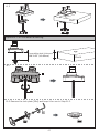
WARNING:
Ensure the bolt and nut
are securely tightened.
0.39-2.56″ (10-65mm)
NOTE: If a hole is needed for grommet installation, be
sure to leave at least 2″ (50mm) from the edge of
desktop and mark where the hole will be drilled. Use
either a 7/16-7/8″ (11-22mm) drill bit for this step.
7/16-7/8″ (11-22mm)
2″ (50mm)
03
B-3
Drill
(Not Included)
7/16-7/8″
(11-22mm)
Drill Bit
(Not Included)
02 03 04 05 06 07 08 09 10 11 12 13 14 15

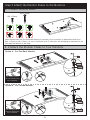
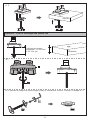
Step 2 Secure the Arms to the Base
02
01
2-1 Push the extension arms [02] into the base, and then tighten the set screws on the
arm joints.
2-2 Slide the compression arms [01] onto the extension arms [02], and then tighten the
set screws.
D
Desk
Desk
D
02
NOTE: The cable management
cover face down.
02
01
01
02
02 03 04 05 06 07 08 09 10 11 12 13 14 15

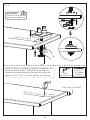
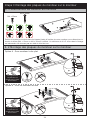
3-2 Attach the Monitor Plates to Your Monitors
Step 3 Attach the Monitor Plates to the Monitors
Option B:For Curved Monitor
Hand thread bolts into the threaded inserts on the back of your monitor to determine which bolt
(M4 x 12mm or M4 x 30mm ) to use. A minimum of 4-5 turns into the threading is required. Do not
turn past the bottom of the hole.
M4 x 12mm
M4 x 30mm
3-1 Select Monitor Bolts
Option A:For Flat Back Monitor
E
E
M-B
M-C
M-D
M-A
M-C
The hanging tab is
directed toward the
top of monitor.
The hanging tab is
directed toward the
top of monitor.
D
O
N
O
T
o
v
e
r
t
i
g
h
t
e
n
D
O
N
O
T
o
v
e
r
t
i
g
h
t
e
n
02 03 04 05 06 07 08 09 10 11 12 13 14 15

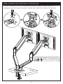
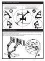
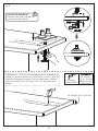
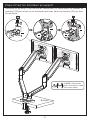
Step 4 Attach the Monitors to the Mount
Loosen the knobs [S] on the compression arms, and slide the monitor plates [04]
downways onto the ends of the arms. Tighten the knobs [S] to fasten the monitors.
04
S
01
04
01
01
S
Desk
HEAVY! You may need
assistance with this step.
02 03 04 05 06 07 08 09 10 11 12 13 14 15

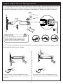
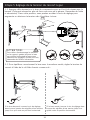
Step 5 Adjust the Gas Spring Tension
5-1 Carefully press down on the compression arm so that it is level with the desk. (This
may require more force than you think. Ask for help if needed). In this position, you can
access the adjustment screw to increase or decrease the tension to balance the arm.
E
5-2 To properly balance the arm with monitor mounted, adjust the spring tension using
the supplied Allen key as follows:
If the arm rises, turn the adjustment screw
clockwise until it stays in a horizontal position.
If the arm drops, turn the adjustment screw
counter-clockwise until it stays in a horizontal
position.
5-1
5-2
CAUTION:
To avoid damage to monitor or mount,
always keep the arm in a horizontal
position while making adjustments.
Again, ask for assistance if needed.
02 03 04 05 06 07 08 09 10 11 12 13 14 15

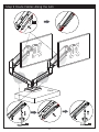
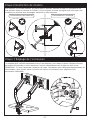
Step 6 Rotation Restriction
Step 7 Tilt Adjustment
To ensure proper stability, do not position monitor behind base. Monitor and arms should remain
over the desktop. Failure to do so may cause instability, resulting in property damage or injury.
E
T
TightenTighten
Loosen
Loosen
The monitor should adjust easily when moved, then stay in place. Adjust the tilt tension bolt if
your monitor naturally tilts up or down.
NOTE: If you do not intend to adjust the tilt for different viewing locations, you can tighten
the tilt tension bolt to prevent unwanted movement.
Desk
Incorrect orientation Correct orientation
02 03 04 05 06 07 08 09 10 11 12 13 14 15

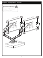
Step 8 Rotation Adjustment
Desk
360° Rotation
360° Rotation
WARNING:
Ensure the monitor bolts and bolts
securing the monitors to the mount
are fully tightened before rotation.
02 03 04 05 06 07 08 09 10 11 12 13 14 15

Desk
Step 9 Route Cables Along the Arm
07
E E
02 03 04 05 06 07 08 09 10 11 12 13 14 15

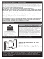
CONSIGNES DE SECURITE IMPORTANTES
Restrictions de poids
Vérifier le Modèle VESA du moniteur avant l’Installation
• Veuillez lire attentivement toutes les instructions avant de tenter l'installation. Si les
instructions ne vous semblent pas claires ou si vous avez des questions, veuillez contacter
notre ligne d'assistance technique au 1-800-556-0533 (US/CA) / 44-808-196-3874
(UK) ou le service client à [email protected].
ATTENTION : évitez les potentiels dommages corporels et aux biens!
• Ne pas utilizer ce produit dans le cas où cet instruction n’a pas indiqué. Ne pas dépasser
le poids limité. Nous ne sommes pas responsables des dommages causés par le montage
incorrect ou l’utilisation inappropriée.
• Ce produit contient des bras d'assistance à gaz qui sont sous haute pression. Ne
perforez pas ces bras et n'exposez pas les bras au feu ou aux flammes. Si le produit est
ou devient défectueux, veuillez contacter notre ligne d'assistance technique au
1-800-556-0533 (US/CA) / 44-808-196-3874 (UK) ou le service client à
• N'utilisez pas ce produit sur des bureaux en panneaux de particules ou autres bois mous.
• Les informations contenues dans ce manuel ne couvrent pas toutes les conditions ou
variables possibles en relation avec l'installation de ce produit.
Si le motif VESA de votre moniteur est inférieur à 75 x 75mm / 3 x 3 po ou supérieur
à 100 x 100mm / 3,9 x 3,9 po, ce support n'est PAS COMPATIBLE avec votre
moniteur. Veuillez contacter notre service client à [email protected] pour trouver
un produit compatible.
Minimum : 75 x 75mm / 3 x 3 po (L x H)
Maximum : 100 x 100mm / 3,9 x 3,9 po (L x H)
Mesurez le modèle VESA de votre
téléviseur :
Maximum : 100mm/3,9 po
Maximum :
100mm/3,9 po
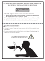
Si votre moniteur pèse plus
lourd, n'utilisez pas ce produit.
Le moniteur ne doit pas
dépasser le poids maximal
indiqué.
AVERTISSEMENT
NE PAS dépasser le poids maximum indiqué. Ce
système de montage est destiné à être utilisé unique-
ment dans la plage de poids indiquée. L'utilisation avec
des produits plus lourds que la limite de poids
maximale peut entraîner une défaillance du support et
causer des dommages potentiels et/ou des blessures.
Il est de la responsabilité de l'installateur de vérifier le
poids total des moniteurs et de tout accessoire
attaché. Ne pas dépasser la limite de poids indiquée.
2-10kg
(4,4-22 livres)
16 17 18 19 20 21 22 23 24 25 26 27 28 29

Caractéristiques du produit
270°270°
270°270°
360°360°
180°180°360°360°
180°180°
+90°/-45°
360°
Montage à l'aide d'un passe-fil
10 à 65mm (0,39-2,56 po)
Montage à l'pince de serrage en C
10 à 80mm (0,39-3,15 po)
16 17 18 19 20 21 22 23 24 25 26 27 28 29

NE PAS régler la tension sans moniteur attaché.
1. Vérifiez que le poids de votre moniteur (y compris les accessoires)
est compris entre 4,4–22 livres (2–10kg).
2. Les informations sur le poids du moniteur se trouvent dans sa boîte
ou dans son manuel.
3. Assurez-vous que le moniteur a été solidement fixé au support.
LE REGLAGE DES TENSIONS NE DOIT ETRE EFFECTUE
QU’APRES L’INSTALLATION DU MONTAGE
ATTENTION
AVERTISSEMENT :
• Le bras du ressort à gaz est sous pression et doit être manipulé avec
précaution.
• Si vous ne suivez pas les instructions, vous risquez d'endommager le
support et/ou de vous blesser.
AVERTISSEMENT!
16 17 18 19 20 21 22 23 24 25 26 27 28 29

Liste des Pièces et de Quincaillerie Fournies
5/32 po (4mm)
Petite clé Allen
[D] × 1
M4 × 12mm
Boulon
[M-A] × 8
D4
Rondelle
[M-C] × 8
M4 × 30mm
Boulon
[M-B] × 8
L13mm
Entretoises
[M-D] × 8
1/4 po (6mm)
Grande clé Allen
[E] × 1
M6 x 10mm
Boulon
[A] × 2 Écrou Papillon
[B] × 1
Boulon à OEillet
[C] × 1
01 × 2
Bras de compression 02 × 2
Bras d’extension 03 × 1
Base 04 × 2
Plaque de moniteur
05 × 1
Plaque de connection 06 × 1
Pince de bureau 07 × 2
Cache de passage de câbles
Pièces et matériel fournis
Outils nécessaires (NON Inclus)
AVERTISSEMENT : Ce produit contient des petits objets susceptibles de présenter un risque
d'étouffement en cas d'ingestion.
Avant de commencer l'assemblage, vérifiez que toutes les pièces sont incluses et en bon état.
N'utilisez pas de pièces endommagées ou défectueuses. Si vous avez besoin de pièces de
rechange, veuillez contacter notre ligne d'assistance technique au 1-800-556-0533 (US/CA) /
44-808-196-3874 (UK) ou le service client à [email protected].
• VEUILLEZ NOTER : le matériel inclus dans cet ensemble ne sera pas utilisé en totalité.
Mètre ruban Foreuse (en option) 11 à 22mm (7/16 po-7/8 po)
Mèche à bois (en option)
16 17 18 19 20 21 22 23 24 25 26 27 28 29

Option A : Pour le montage du collier de serrage
Étape 1 Installation de la base
Épaisseur de bureau
compatible : 10 à 80mm
(0.39 po-3.15 po)
Bureau
03
06
05
D
A
EE
D
A
03
A-1
A-2
16 17 18 19 20 21 22 23 24 25 26 27 28 29
La page est en cours de chargement...
La page est en cours de chargement...
La page est en cours de chargement...
La page est en cours de chargement...
La page est en cours de chargement...
La page est en cours de chargement...
La page est en cours de chargement...
La page est en cours de chargement...
La page est en cours de chargement...
La page est en cours de chargement...
La page est en cours de chargement...
La page est en cours de chargement...
-
 1
1
-
 2
2
-
 3
3
-
 4
4
-
 5
5
-
 6
6
-
 7
7
-
 8
8
-
 9
9
-
 10
10
-
 11
11
-
 12
12
-
 13
13
-
 14
14
-
 15
15
-
 16
16
-
 17
17
-
 18
18
-
 19
19
-
 20
20
-
 21
21
-
 22
22
-
 23
23
-
 24
24
-
 25
25
-
 26
26
-
 27
27
-
 28
28
-
 29
29
-
 30
30
-
 31
31
-
 32
32


HUANUO HNDSK4 Guide d'installation
- Catégorie
- Supports de bureau à panneau plat
- Taper
- Guide d'installation
dans d''autres langues
- English: HUANUO HNDSK4 Installation guide

