Valor 1700JN/JP Le manuel du propriétaire
- Taper
- Le manuel du propriétaire

4005427-11
©2018, Miles Industries Ltd.
This appliance may be installed in an after-
market permanently located, manufactured
(mobile) home where not prohibited by local
codes.
This appliance is only for use with the type
of gas indicated on the rating plate. This
appliance is not convertible for use with
other gases, unless a certifi ed kit is used.
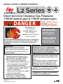
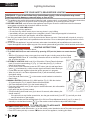
HOT GLASS WILL
CAUSE BURNS.
DO NOT TOUCH GLASS
UNTIL COOLED.
NEVER ALLOW CHILDREN
TO TOUCH GLASS.
DANGER
!
A barrier designed to reduce the risk of burns from the hot
viewing glass is provided with this appliance and shall be
installed for the protection of children and other at-risk
individuals.
Ce guide est disponible en français sur demande.
This appliance is a domestic room-heating
appliance. It must not be used for any other
purposes such as drying clothes, etc.
This appliance is suitable for installation in
a bedroom or bed sitting room.
INSTALLER
Leave this manual
with the appliance.
CONSUMER
Retain this manual
for future reference.
Please read this manual
BEFORE installing and
operating this appliance.
INSTALLATION & OWNER’S MANUAL
— Do not store or use gasoline or other
fl ammable vapors and liquids in the
vicinity of this or any other appliance.
— WHAT TO DO IF YOU SMELL GAS
▪ Do not try to light any appliance.
▪ Do not touch any electrical switch; do
not use any phone in your building.
▪ Leave the building immediately.
▪ Immediately call your gas supplier from
a neighbor’s phone. Follow the gas
supplier’s instructions.
▪ If you cannot reach your gas supplier,
call the fi re department.
— Installation and service must be
performed by a qualifi ed installer,
service agency or the gas supplier.
! WARNING
FIRE OR EXPLOSION HAZARD
Failure to follow safety warnings exactly
could result in serious injury, death, or
property damage.
Direct Vent Zero Clearance Gas Fireplaces
1700JN (natural gas) & 1700JP (propane gas)
This manual contains instructions to install the
ENGINE ONLY. A trim kit is REQUIRED to
complete the installation. A barrier screen is
provided with the trim kit. Refer to the manual
supplied with the trim for installation.
L2 Series

2
Table of Contents
Specifi cations .......................................................20
Overview................................................................21
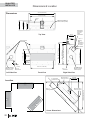
Dimensions & Location ........................................22
Mantel & Hearth Clearances ................................23
Framing Requirements ........................................ 25
Venting ...................................................................28
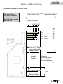
Co-axial Venting.................................................... 29
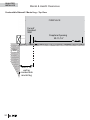
Co-linear Venting ..................................................33
Installation Planning ............................................ 35
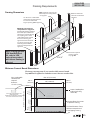
Plan Wall Finish ....................................................... 35
Installation .............................................................37
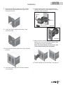
Unpack the Appliance ..............................................37
Install the Standoff s .................................................37
Remove Heat Shield ................................................ 37
Convert Vent Outlet (if required) ..............................37
Fit optional LDK HeatShift Duct Kit’s take-off collars
to appliance (if used) ............................................ 37
Remove Window ..................................................... 38
Fit the Appliance into Framing .................................38
Complete Installation of optional LDK HeatShift Duct
Kit (if used)............................................................38
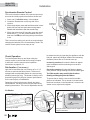
Install Electrical Wiring (for optional accessories) ...39
Set-up Gas Supply .................................................. 40
Install Liners ............................................................ 42
Install Driftwood Kit 1705DWK ................................ 44
Install Decorative Glass Murano 1700DGM ............47
Install Rocks & Shale Set 1714RSS ........................48
Install Split Wood Kit 1700SWK .............................. 50
Refi t Window ...........................................................53
Install Remote Battery and Wall Switch Kit RBWSK
(required) ..............................................................54
Synchronize Remote Control ................................... 56
Check Operation ...................................................... 56
Set Aeration (if necessary) ......................................56
Install Trim and Barrier Screen ................................57
Install Remote Control Handset Wall Holder ...........57
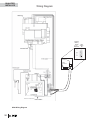
Wiring Diagram .....................................................58
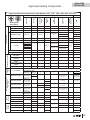
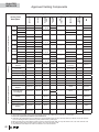
Approved Venting Components ..........................59
Commonwealth of Massachusetts......................61
Warranty ................................................................63
Spare Parts............................................................64
Massachusetts: The piping and fi nal
gas connection must be performed by a
licensed plumber or gas fi tter in the State of
Massachusetts. Also, see Carbon Monoxide
Detector requirements on page 61.
Designed and Manufactured by / for
Miles Industries Ltd.
190–2255 Dollarton Highway,
North Vancouver, BC, CANADA V7H 3B1
Tel. 604-984-3496 Fax 604-984-0246
www.valorfi replaces.com
FOR THE OWNER FOR THE QUALIFIED INSTALLER
The information contained in this installation manual
is believed to be correct at the time of printing. Miles
Industries Ltd. reserves the right to change or modify
any information or specifi cations without notice.
Miles Industries Ltd. grants no warranty, implied or
stated, for the installation or maintenance of your
heater, and assumes no responsibility for any conse-
quential damage(s).
Warranty Card at the
back of this manual.
W
A
R
R
A
N
T
Y
P
R
O
G
R
A
M
W
A
R
R
A
N
T
Y
P
R
O
G
R
A
M
V
A
L
O
R
C
O
M
F
O
R
T
V
A
L
O
R
C
O
M
F
O
R
T
V
A
L
O
R
C
O
M
F
O
R
T
© Copyright Miles Industries Ltd., 2018. All rights reserved.
Safety and Your Fireplace ......................................3
Introduction .............................................................6
Locating Fireplace & Lighting Information Card ........ 6
Operating Your Fireplace for the First Time ............... 6
Operating Your Fireplace .......................................7
Fireplace Control Devices ......................................... 7
How to Turn Your Fireplace ON ................................. 7
How to Turn Your Fireplace OFF (and pilot) ..............7
How to Ensure Your Fireplace Cannot
Be Turned ON Inadvertently ................................... 7
Using the Remote Control ..................................... 8
Using the Wall Switch ..........................................13
Kits & Accessories ...............................................13
Lighting Instructions ............................................14
Maintaining Your Fireplace .................................. 15
Servicing Your Fireplace .......................................... 15
Annual Inspection .................................................... 15
Cleaning Your Fireplace .......................................... 16
Checking Pilot and Burner Flames .......................... 18
Replacing Batteries ................................................. 19
Using Handset Wall Holder ...................................... 19
Warranty ................................................................63

3
Safety and Your Fireplace
SAFETY AND YOUR FIREPLACE
!
Children and adults should be alerted to the hazards
of high surface temperature and should stay away to
avoid burns or clothing ignition.
Young children should be carefully supervised
when they are in the same room as the appliance.
Toddlers, young children and others may be susceptible
to accidental contact burns. A physical barrier is
recommended if there are at-risk individuals in the
house. To restrict access to a fi replace or stove, install
an adjustable safety gate to keep toddlers, young
children and other at-risk individuals out of the room
and away from hot surfaces.
Do not place furniture or any other combustible house-
hold objects within 36” of the fi replace front.
Read and understand all instructions carefully before
starting the installation. Failure to follow these instal-
lation instructions may result in possible fi re hazard and
will void the warranty.
Prior to the fi rst fi ring of the fi replace, read the
Owner’s information section of this manual.
Do not use this appliance if any part has been under
water. Immediately, call a qualifi ed service technician
to inspect the unit and to replace any part of the control
system and any gas control that has been under water.
This unit is not for use with solid fuel.
Installation and repair should be performed by a
qualifi ed service person. The appliance and venting
system should be inspected before initial use and at
least annually by a professional service person. More
frequent cleaning may be required due to excessive lint
from carpeting, bedding, etc. It is imperative that the
unit’s control compartment, burner, and circulating air
passageways be kept clean to provide for adequate
combustion and ventilation air.
Always keep the appliance clear and free from
combustible materials, gasoline, and other fl ammable
vapors and liquids.
Never obstruct the fl ow of combustion and venti-
lation air. Keep the front of the appliance clear of all
obstacles and materials for servicing and proper opera-
tion.
Due to the high temperature, the appliance should be
located out of traffi c areas and away from furniture and
draperies.
Clothing or fl ammable material should not be placed
on or near the appliance.
This unit must be used with a vent system as de-
scribed in this installation manual. No other vent sys-
tem or components may be used.
This gas fi replace and vent assembly must be vented
directly to the outside and must never be attached to
a chimney serving a separate solid fuel burning appli-
ance. Each gas appliance must use a separate vent
system. Common vent systems are prohibited.
Inspect the external vent cap on a regular basis to
make sure that no debris, plants, trees, shrubs are inter-
fering with the air fl ow.
Do not operate this appliance with the glass door
removed, cracked, or broken. Replacement of the
glass door should be performed by a licensed or qualifi ed
service person. Do not strike or slam the glass door.
The glass door assembly shall only be replaced as
a complete unit, as supplied by the fi replace manufac-
turer. No substitute material may be used.
A barrier designed to reduce the risk of burns from
the hot viewing glass is provided with this appliance and
shall be installed for the protection of children and
other at-risk individuals.
Do not use abrasive cleaners on the glass door assem-
bly. Do not attempt to clean the glass door when it is hot.
If the barrier becomes damaged, the barrier shall
be replaced with the manufacturer’s barrier for this
appliance.
Turn off the gas before servicing this appliance. It is
recommended that a qualifi ed service technician per-
form an appliance check-up at the beginning of each
heating season.
Any safety screen, guard or barrier removed for
servicing the appliance, must be replaced prior to
operating the appliance.
Be careful not to put any decorating objects sensi-
tive to heat to close above or around the fi replace as it
gets very hot when operating.
Do not use this heater as a temporary source of
heat during construction.
This appliance is a domestic room-heating appliance.
It must not be used for any other purposes such as dry-
ing clothes, etc.
The glass door assembly must be in place and sealed
before the unit can be placed into safe operation.
This product can potentially expose you to chemicals
including Benzene which are known to the State of
California to cause cancer and birth defects or other
reproductive harm. For more information go to
www.P65Warnings.ca.gov
WARNING:

4
Parts of your Valor Fireplace become
extremely hot while in operation.
The glass viewing window temperature
can exceed 500 F at full capacity.
Momentary contact with a hot glass
surface can cause a severe burn, even
if the fi replace is operating at reduced
heating capacity.
The glass window will remain hot
for an extended period of time after
the fi replace has been turned off .
Ensure that children are prevented from
touching the fi replace during the cool
down period.
Toddlers and Young Children must
be closely supervised at all times
when they are in the same room as
the operating fi replace. They lack full
awareness of danger and rely on your
protection. Toddlers, in particular, do
not have the motor skills and response
refl exes to withdraw in the event of
accidental contact with a hot surface.
A physical barrier is strongly
recommended if there are young
children, or at-risk individuals in the house.
Install an approved after-market safety
gate to keep toddlers, young children and
other at-risk individuals a safe distance
from the fi replace.
Keep the remote control handset out
of reach of children at all times. A wall
mount storage holster is provided with
your remote control handset.
Ensure that the fi replace, including
the pilot light, is completely turned
off when children are present and close
supervision and safety barriers are not
available—see page 7 of this manual.
If the fi replace is not going to be used
for the summer or any extended period
of time, remove the batteries from the
remote control handset and remote
battery box. It is recommended that
batteries are replaced annually in any
event—see page 19.
Read and carefully follow all safety warnings and
operating instructions contained in your owner’s manual
Replacement manuals are available by contacting the Valor Service Department
at 1-800-468-2567 or visit www.valorfi replaces.com.
Safety and Your Fireplace
!
FOLLOW THESE IMPORTANT CHILD SAFETY
PRECAUTIONS AND RECOMMENDATIONS

5
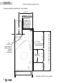
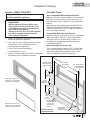
Front outlet
Side
outlet
This manual and particularly the preceeding and following pages contain very important information regarding
the safe operation of your fi replace as well as maintenance instructions. Read carefully before operating your
fi replace and pay special attention to the safety warnings.
A heating gas appliance does require safe handling. For this reason, we very strongly recommend children are not
allowed to touch the fi replace or controls. Install a screen or barrier in front of the fi replace to protect your children
against severe burns.
This appliance is designed and approved as a supplemental heater and provides the potential for most
energy conservation when used while attended. The use of an alternate primary heat source is advisable.
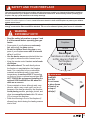
Do not put
furniture or other objects
in this space in front of
the replace:
36” (0.9 m)
Fireplace
Hearth
WARNING
HeatShift
Duct Kit:
Do not cover
or place items
in front of or
on top of
outlet(s)!
!
!WARNING
EXTREMELY HOT!!!
• Read the safety information on pages 3 and
4 of this manual before operating your gas
heater.
• Some parts of your fi replace are extremely
hot, particularly the glass window.
• Do not let children touch the glass or any
parts of your fi replace even after it is turned
off as it is still hot.
• Use the barrier screen provided with the trim
or a gate to reduce the risk of severe burns.
• Keep the remote control handset out of reach
of children.
• Hot wall surfaces! The wall directly above
the fi replace is very hot when the fi replace
heats. It is constructed of non-combustible
materials and although safe, it may reach
temperatures in excess of 200º F depending
on choice of trims or optional accessories. DO
NOT TOUCH! We recommend installing the
optional LDK HeatShift Duct Kit when hot
walls are a concern.
•
•
Some materials or items, although safe, may
Some materials or items, although safe, may
discolor, shrink, warp, crack, peel, and so on
discolor, shrink, warp, crack, peel, and so on
because of the heat produced by the fi replace.
because of the heat produced by the fi replace.
Avoid placing
Avoid placing
candles, paintings, photos, and
candles, paintings, photos, and
other items
other items
sensitive to heat
sensitive to heat
within 36 inches
(0.9 m) around the fi replace.
•
•
Solid wood fl ooring in front of the fi replace (if
Solid wood fl ooring in front of the fi replace (if
allowed) may shrink during the heating season
allowed) may shrink during the heating season
due to heat.
due to heat.
SAFETY AND YOUR FIREPLACE
!

6
WARNING
DO NOT ATTEMPT TO TOUCH THE DATA CARD
WHILE THE FIREPLACE IS STILL HOT! Let the
fi replace cool fi rst before touching it.
!
Operating Your Fireplace for the First
Time
When operating your new fi replace for the fi rst time,
some vapors may be released due to the burning of
curing compounds used in the manufacture of the
appliance. They may cause a slight odor and could
cause the fl ames to be the full height of the fi rebox, or
even slightly higher, for the fi rst few hours of operation.
It is also possible that these vapors could set off any
smoke detection alarms in the immediate vicinity.
These vapors are quite normal on new appliances. We
recommend opening a window to vent the room. After
a few hours use, the vapors will have disappeared and
the fl ames will be at their normal height.
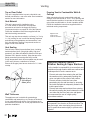
Flame Supervision Device
For your safety, this appliance is fi tted with a fl ame
supervision device which will shut-off the gas supply
if, for any reason, the pilot fl ame goes out. This device
incorporates a fi xed probe, which senses the heat
from the pilot fl ame. If the probe is cool, the device will
prevent any gas fl ow unless manually lighting the pilot.
See full lighting instructions on page 14 of this manual.
Introduction
Thank You ...
For purchasing a Valor by Miles Industries. Your new
radiant gas heater is a technical appliance that must
be installed by a qualifi ed dealer. Each Valor fi replace
is fully tested during the production process for your
safety and comfort.
Your unit has been professionally installed by:
Dealer Name: ________________________________
Phone Number :_______________________________
Should you encounter an operational problem, call
your dealer immediately.
Do not try to repair the unit as you may cause an
injury or damage the fi replace.
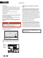
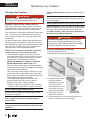
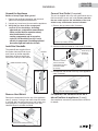
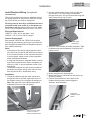
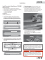
Locating Fireplace & Lighting Information
Card
The Fireplace and Lighting Information card is located at
the right hand side of the fi replace opening. The card is
attached under the plinth.
To access the card, remove the barrier screen, side
doors and the plinth. Grab the card and pull it out.
There is important information on both sides of the
card.
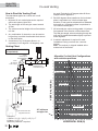
739MN
FOR NATURAL GAS POUR LE GAZ NATUREL
750
24,000
6,500
3.2"
5.0"
4006176N/01
CIRCULATING FAN KIT 755CFK VENTILAT EUR POUR CIRCULATION D'AIR 755CFK
#4003360-741, #4003293-742, #4003313-745, #4003426-765, #4004666 772
120V, 60Hz, LESS THAN 1A 120V, 60Hz, MOINS DE 1A
739N 10000
Fireplace
model
Serial
number
Performance of propane gas appliances may be
aff ected by the quality of commercial gas sup-
plied in your area.
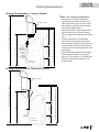
Info
card
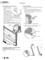
Window
The info card is located behind the front
panel below the window.
OWNER’S
INFORMATION

7
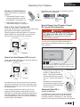
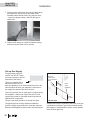
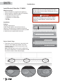
Gas valve
Battery holder
& wall switch
Fireplace
Receiver Gas valve
The receiver and gas valve are located on the bottom of the
fi replace behind the front panel. The battery holder is located
next to the wall switch.
Thermostatic
Remote
Control
Wall SwitchRemote control
handset
ON: parallel to pipe OFF:
perpendicular
to pipe
Wall Switch
Fireplace Control Devices
There are two ways to control your
fi replace.
1. Thermostatic Remote Control
can be programmed to function
automatically—see pages 8–12;
2. Wall Switch turns fi re on, off and
controls fl ame height—see page 13.
How to Turn Your Fireplace ON
Press and hold button(s) until a short beep confi rms the
start sequence has begun; release buttons.
Continuing beeps confi rm the ignition is in process.
When the pilot is lit, the gas fl ows—see Using the
Remote Control section for more information.
How to Turn Your Fireplace OFF (and pilot)
Press and hold the OFF button for a second (either on
the handset or the wall switch).
If the fl ames are on, they go down and you hear the
valve motor wind down. You hear a clunk and a beep
indicating that the valve has received the signal from
the remote control.
In the unlikely event that you cannot turn off your
fi replace with the remote control handset, use the
wall switch; if the wall switch malfunctions and will not
turn off the fi replace, wait 6 hours and the fi replace
will automatically go to pilot. You can then access the
controls inside your fi replace.
Alternately, turn off gas supply. In all cases, call your
dealer for service assistance.
How to Ensure Your Fireplace Cannot
Be Turned ON Inadvertently
You can use one of the two following methods to
ensure that your fi replace will not turn on when you
don’t want it on.
• On gas valve, turn dial from ON
position to MAN position as
shown. Turning dial to MAN will
ensures that main burner cannot
come on. The pilot will remain on
if lit.
• Alternately, remove all batteries
from the battery holder next to the
wall switch as well as the battery
from the handset.
Automatic Shut-Off (in
certain conditions)
Your fi replace’s remote control is equipped with an
automatic shut-off mechanism which is activated
in certain conditions. See page 12 in the Using the
Remote Control section for a description of this feature.
Operating Your Fireplace
WARNING
RISKS OF SEVERE BURNS! SURFACES OF
THE FIREPLACE ARE VERY HOT DURING
OPERATION! Ensure fi replace has cooled off
before accessing controls.
!
Wall SwitchRemote control
handset
OWNER’S
INFORMATION

8
Using the Remote Control
5DGLR)UHTXHQF\
0+]IRU86$DQG&DQDGD
7KLVGHYLFHFRPSOLHVZLWK3DUWRIWKH)&&5XOHV
DQGZLWK,QGXVWU\&DQDGDOLFHQVHH[HPSW566
VWDQGDUGV2SHUDWLRQLVVXEMHFWWRWKHIROORZLQJWZR
FRQGLWLRQV
WKLVGHYLFHPD\QRWFDXVHKDUPIXOLQWHUIHUHQFHDQG
WKLVGHYLFHPXVWDFFHSWDQ\LQWHUIHUHQFHUHFHLYHG
LQFOXGLQJLQWHUIHUHQFHWKDWPD\FDXVHXQGHVLUHG
RSHUDWLRQ
127(%HIRUHXVLQJWKHUHPRWHFRQWUROV\VWHPIRU
WKH¿UVWWLPHWKHUHFHLYHUDQGWKHKDQGVHWPXVWEH
V\QFKURQL]HG6HHWKHVHFWLRQ Synchronize Remote
Control
,03257$17BEFORE YOU BEGIN, please note that
on this system, the settings of time, temperature and
automatic ON/OFF can only be programmed when
the function display is fl ashing. Be patient when
programming as it can take a few seconds to set.
1RWH,QWKH7(03RU7,0(5PRGHVWKHUHPRWHKDQGVHW
VHQVHVWKHURRPWHPSHUDWXUHDQGDGMXVWVWKHÀDPH
DFFRUGLQJO\
7RFRPPXQLFDWHWKHKDQGVHWVKRXOGEHZLWKLQIHHW
PHWHUVRIWKH¿UHSODFH
Do not leave the handset on the mantel or hearth.
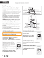
6(7(scrolls
through
modes and
settings)
2))(returns
to set mode,
turns the burner
and the pilot o)
Large ame
button (ames
up, sets hours,
temperature)
Small ame
button (ames
down and o,
sets minutes,
temperature)
Current
temperature
(F or C)
Current time
(12 or 24 hour clock)
Modes (Manual,
Temperature, Timer)
Handset
sensor
Battery status
Current
programmed
period (Timer)
Period
start or end
(Temp, Timer)
:KHQWKHSLORWLVRႇLWZLOOWDNH
PLQXWHVEHIRUHLWFDQEHOLWDJDLQ
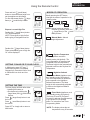
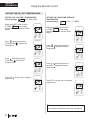
72785121$33/,$1&( 7278512))$33/,$1&(
)/$0(+(,*+7$'-8670(17
2QWKHYDOYHWXUQ0$1NQRERQWKH21IXOO
FRXQWHUFORFNZLVHSRVLWLRQ
3ODFH212))VZLWFKLIHTXLSSHGLQ,21SRVLWLRQ
67$1'%<02'(3LORW)ODPH
3UHVVDQGKROGVPDOOÀDPHWRVHWDSSOLDQFHDW
SLORWÀDPH
6LPXOWDQHRXVO\SUHVVWKH2))DQG
ODUJHÀDPHEXWWRQVXQWLODVKRUW
EHHSFRQ¿UPVWKHVWDUWVHTXHQFHKDV
EHJXQUHOHDVHEXWWRQV
&RQWLQXLQJEHHSVFRQ¿UPWKHLJQLWLRQLV
LQSURFHVV
2QFHSLORWLJQLWLRQLVFRQ¿UPHGWKHUHLV
PDLQJDVÀRZ
$IWHUPDLQEXUQHULJQLWLRQWKHKDQGVHW
ZLOODXWRPDWLFDOO\JRLQWRPDQXDO0$1
FRQWUROPRGH
3UHVV2))EXWWRQ
:KHQWKHSLORWLVRႇLWZLOOWDNH
PLQXWHVEHIRUHLWFDQEHOLWDJDLQ
,QVWDQGE\PRGH3UHVVDQGKROG
ODUJHÀDPHEXWWRQWRLQFUHDVH
ÀDPHKHLJKW
&$87,21
:KHQSLORWLJQLWLRQLVFRQ¿UPHGPRWRUWXUQV
DXWRPDWLFDOO\WRPD[LPXPÀDPHKHLJKW
OWNER’S
INFORMATION

9
Using the Remote Control
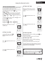
6(77,1*7+(7,0(
6(77,1*&+525)+5&/2&.
02'(62)23(5$7,21
127(0DQXDOPRGHFDQDOVREH
UHDFKHGE\SUHVVLQJHLWKHUWKH
ODUJHÀDPHRUWKHVPDOO
ÀDPHEXWWRQV
3UHVVDQGKROGVPDOOÀDPH
EXWWRQWRGHFUHDVHÀDPHKHLJKWRUWR
VHWWKHDSSOLDQFHDWSLORWÀDPH
)RU¿QHDGMXVWPHQWWDSWKHODUJH
ÀDPHRUVPDOOÀDPHEXWWRQV
'RXEOHFOLFNVPDOOÀDPHEXWWRQ
³/2´ZLOOEHGLVSOD\HG
127()ODPHJRHVWRKLJK¿UH¿UVW
EHIRUHJRLQJWRGHVLJQDWHGORZ¿UH
,Q0$1PRGHSUHVV2))DQG
VPDOOÀDPHEXWWRQVXQWLOGLVSOD\
FKDQJHVIURP)DUHQKHLWKRXUFORFN
WR&HOVLXVKRXUFORFNDQGYLFH
YHUVD
7KHWLPHGLVSOD\ZLOOÀDVKDIWHUHLWKHU
,QVWDOOLQJWKHEDWWHU\RU
6LPXOWDQHRXVO\SUHVVLQJWKH
ODUJHÀDPHDQGVPDOOÀDPH
EXWWRQV
3UHVVODUJHÀDPHEXWWRQWRVHW
WKHKRXU
3UHVVVPDOOÀDPHEXWWRQWRVHW
WKHPLQXWH
3UHVV2))RUVLPSO\ZDLWWRUHWXUQWR
0$1PRGH
'RXEOHFOLFNODUJHÀDPHEXWWRQ
)ODPHDXWRPDWLFDOO\JRHVWRKLJK¿UH
³+,´ZLOOEHGLVSOD\HG
0DQXDO0RGH0DQXDO
)ODPH+HLJKW$GMXVWPHQW
([SUHVV/RZDQG+LJK)LUH
'D\WLPH7HPSHUDWXUH
0RGH$SSOLDQFHPXVWEHLQ
VWDQGE\PRGHSLORWLJQLWHG7KH
URRPWHPSHUDWXUHLVPHDVXUHGDQG
FRPSDUHGWRWKHVHWWHPSHUDWXUH
7KHÀDPHKHLJKWLVWKHQDXWRPDWLFDOO\
DGMXVWHGWRDFKLHYHWKH'D\WLPH6HW
7HPSHUDWXUH
x 2
x 2
MAN
TEMP
%ULHÀ\SUHVVLQJWKH6(7EXWWRQ
FKDQJHVWKHPRGHRIRSHUDWLRQLQWKH
IROORZLQJRUGHU
ĺĺ
ĺĺDQGEDFNWR
MAN
MAN
TEMP
TEMP
TIMER
1LJKWWLPH6HWEDFN
7HPSHUDWXUH0RGH$SSOLDQFHPXVW
EHLQVWDQGE\PRGHSLORWLJQLWHG
7KHURRPWHPSHUDWXUHLVPHDVXUHG
DQGFRPSDUHGWRWKH1LJKWWLPH
6HWEDFNWHPSHUDWXUH7KHÀDPH
KHLJKWLVWKHQDXWRPDWLFDOO\DGMXVWHG
WRDFKLHYHWKH1LJKWWLPH6HWEDFN
7HPSHUDWXUH
7LPHU0RGH$SSOLDQFHPXVW
EHLQVWDQGE\PRGHSLORWLJQLWHG
7KHWLPHUV3DQG33URJUDP
3URJUDPHDFKFDQEHSURJUDPPHG
WRJR21DQG2))DWVSHFL¿F
WLPHV)RULQVWUXFWLRQVVHH7LPHU
3URJUDPPLQJ0RGH
127(7KHGLVSOD\VKRZVWKHVHW
WHPSHUDWXUHHYHU\VHFRQGV
TEMP
TIMER
OWNER’S
INFORMATION

10
Using the Remote Control
6(77,1*7+(212))7(03(5$785(6
%ULHÀ\SUHVV6(7EXWWRQWRVFUROO
WR7(03VXQPRGH
+ROGWKH6(7EXWWRQXQWLOWKH7(03
ÀDVKHV
3UHVVODUJHÀDPHEXWWRQ
WRLQFUHDVHWKH'D\WLPH6HW
7HPSHUDWXUH
3UHVVVPDOOÀDPHEXWWRQ
WRGHFUHDVH'D\WLPH6HW
7HPSHUDWXUH
3UHVV2))RUVLPSO\ZDLWWRFRPSOHWH
SURJUDPPLQJ
6(77,1*7+(³'$<7,0(´7(03(5$785( 6(77,1*7+(³1,*+77,0(6(7%$&.´
7(03(5$785(
'HIDXOW6HWWLQJVVXQ&)
'HIDXOW6HWWLQJVPRRQ³´2))
3UHVVODUJHÀDPHEXWWRQWR
LQFUHDVH1LJKWWLPH6HWEDFN
7HPSHUDWXUH
3UHVVVPDOOÀDPHEXWWRQWR
GHFUHDVH1LJKWWLPH6HWEDFN
7HPSHUDWXUH
3UHVV2))RUVLPSO\ZDLWWRFRPSOHWH
SURJUDPPLQJ
%ULHÀ\SUHVV6(7EXWWRQWRVFUROO
WR7(03PRRQPRGH
+ROGWKH6(7EXWWRQXQWLOWKH7(03
ÀDVKHV
TEMP
TEMP
TEMP
TEMP
7LS
6HWWKHGLႇHUHQWSDUDPHWHUVZKHQWKH\DUHÀDVKLQJ
OWNER’S
INFORMATION

11
Using the Remote Control
6(77,1*352*5$07,0(56
<RXFDQSURJUDPWZRSHULRGVRIWLPHEHWZHHQ
DPDQGSPLQHDFKKRXUF\FOH
7KH3URJUDPV3DQG3PXVWEHVHWLQWKHIROORZLQJ
RUGHUGXULQJDKRXUF\FOH
DQG
7KHLFRQLQGLFDWHVWKHEHJLQQLQJRIWKHSHULRG21
DQGWKHLFRQLQGLFDWHVWKHHQGRIWKHSHULRG2))
,I RU WKHSURJUDPPLQJLV
FDQFHOOHG
7RNHHSWKH¿UHSODFH21DOOQLJKWVHWDW
DPDQGDWDP
'HIDXOWVHWWLQJV
3URJUDPDPDP
3URJUDPSPSP
%ULHÀ\SUHVV6(7EXWWRQWRVFUROOWR
7,0(5PRGH
+ROGWKH6(7EXWWRQXQWLO
VXQLVGLVSOD\HGDQGWKHWLPH
ÀDVKHV
%ULHÀ\SUHVV6(7EXWWRQWRVFUROOWR
7,0(5PRRQZKLOHWKHWLPH
ÀDVKHV
3UHVVODUJHÀDPHEXWWRQWRVHW
WKHKRXU
3UHVVODUJHÀDPHEXWWRQWRVHW
WKHKRXU
3UHVVVPDOOÀDPHEXWWRQWRVHW
WKHPLQXWHV
3UHVVVPDOOÀDPHEXWWRQWRVHW
WKHPLQXWHV
6(77,1*3217,0( 6(77,1*3217,0(
%ULHÀ\SUHVV6(7WRVFUROOWR7,0(5PRGHVXQ
ZKLOHWKHWLPHÀDVKHV
)ROORZWKHLQVWUXFWLRQVJLYHQWRVHW321WLPH
6(77,1*32))7,0(
%ULHÀ\SUHVV6(7WRVFUROOWR7,0(5PRGH
PRRQZKLOHWKHWLPHÀDVKHV
)ROORZWKHLQVWUXFWLRQVJLYHQWRVHW32))WLPH
3UHVV2))EXWWRQWRVDYHWKHVHVHWWLQJV7KHWLPHUV
DUHSURJUDPPHG6HHWKHGLDJUDPRQSURJUDPPLQJ
VHTXHQFHVRQWKHIROORZLQJSDJH
7LS
,I\RXZDQWWRSURJUDPRQO\RQHSHULRGSURJUDP
DQGZLWKGHVLUHGWLPHVDQGSURJUDPDQG
ZLWKWKHVDPHWLPHDV
6(77,1*32))7,0(
P1
P1
P1
P1
P1
P1
P2
P2
P2
P2
P2
P2
P1
P1
P1
P1
P1
P1
P2
P2
P2
P2
P2
OWNER’S
INFORMATION

12
Using the Remote Control
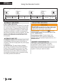
7LPHU3URJUDPPLQJ([DPSOHGHIDXOWWHPSHUDWXUHVVKRZQ
DP²
3
6WDUWWLPH
SP²
3
6WDUWWLPH
DP²
3
6WDUWWLPH
DP²
3
(QGWLPH
SP²
3
(QGWLPH
6HWWHPSÛ) 6HWWHPSÛ)6HWWHPSÛ)
6HWWHPSÛ)
$8720$7,&7851'2:1
$8720$7,&6+872))
/2:%$77(5<,1',&$7,21
+$1'6(75(&(,9(50$7&+
5HPRWHKDQGVHW7KHEDWWHU\LFRQZLOOVKRZ
ZKHQWKHEDWWHU\QHHGVWREHUHSODFHG5HSODFHZLWK
RQH9DONDOLQHEDWWHU\
5HPRWHEDWWHU\KROGHU)UHTXHQWµEHHSV¶IRU
VHFRQGVZKHQWKHYDOYHPRWRUWXUQVLQGLFDWHWKH
EDWWHULHVQHHGWREHUHSODFHG5HSODFHZLWKIRXU9
DONDOLQHEDWWHULHV
7KHUHPRWHFRQWUROKDQGVHWDQGUHFHLYHUDUH
SURJUDPPHGWRIXQFWLRQWRJHWKHU,QFDVHRID
UHSODFHPHQWRIWKHKDQGVHWRUWKHUHFHLYHU\RXZLOO
QHHGWRUHVHWWKHUHFHLYHUWRDOORZWKHPWRIXQFWLRQ
WRJHWKHU&RQWDFW\RXUGHDOHUIRUGHWDLOV
+RXUQR0RWRU0RYHPHQW
0DQXDO0RGH7HPSHUDWXUH7LPHU0RGH7KHYDOYHZLOO
WXUQWRSLORWÀDPHLIWKHUHLVQRFKDQJHLQÀDPHKHLJKW
IRUDKRXUSHULRG,Q7HPSHUDWXUH7LPHU0RGHLIWKH
DPELHQWURRPWHPSHUDWXUHFKDQJHVWKHÀDPHKHLJKW
ZLOODGMXVWDXWRPDWLFDOO\WRPDLQWDLQVHWWHPSHUDWXUH
DQGWKH¿UHZLOOFRQWLQXHWRIXQFWLRQQRUPDOO\7KHYDOYH
ZLOOWXUQWRSLORWÀDPHLIWKHVHWWHPSHUDWXUHDQGWKH
DPELHQWURRPWHPSHUDWXUHUHPDLQWKHVDPHRYHUD
KRXUSHULRG
/RZEDWWHULHVUHFHLYHU:LWKORZEDWWHU\SRZHULQWKH
UHFHLYHUEDWWHU\KROGHUWKHV\VWHPVKXWVRႇWKH¿UH
FRPSOHWHO\7KLVGRHVQRWDSSO\ZKHQWKHSRZHUVXSSO\
LVLQWHUUXSWHG
2Q'HPDQG3LORW7KLVJUHHQIHDWXUHHOLPLQDWHV
JDVHQHUJ\FRQVXPSWLRQGXULQJH[WHQGHGDSSOLDQFH
LQDFWLYLW\:KHQWKHDSSOLDQFHLVLQDFWLYHIRUGD\V
WKHV\VWHPDXWRPDWLFDOO\H[WLQJXLVKHVWKHSLORW7KLV
IHDWXUHKHOSVWKHFRQVXPHUUHDOL]HFRVWEHQH¿WVE\
DXWRPDWLFDOO\HOLPLQDWLQJHQHUJ\FRQVXPSWLRQGXULQJ
QRQKHDWLQJPRQWKVDQGOLPLWHGXVH
&$87,21
'212786(DVFUHZGULYHURURWKHUPHWDOOLFREMHFW
WRUHPRYHWKHEDWWHULHVIURPWKHEDWWHU\ER[RUWKH
KDQGVHW7KLVFRXOGFDXVHDVKRUWFLUFXLW
OWNER’S
INFORMATION

13
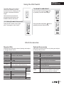
Using the Wall Switch
TO TURN APPLIANCE ON and OFF
TO ADJUST FLAME HEIGHT
Press ON-OFF button once to light
pilot. Press again to shut of pilot.
Press and hold large fl ame button
to gradually increase fl ame height.
Press and hold small fl ame button to
gradually decrease fl ame height.
The Wall Switch can be used to
control your fi replace. You can
turn the pilot on or off and you can
increase or decrease the fl ame
height.
Note that the thermostat and
programming functions are not
available with the wall switch.
Required Kits
Information accurate at the time of printing and subject
to change without notice.
Optional Accessories
Information accurate at the time of printing and subject
to change without notice.
Kits & Accessories
Fuel Beds (choose one)
1705DWK Driftwood Set Kit
1700DGM Decorative Glass Murano
1714RSS Rock & Shale Set
1700SWK Split Wood Kit
Liners (choose one)
1715FBL Linear Fluted Black Liner Set
1725RGL** Linear Refl ective Glass Liner Set
(**Add 1725RGL-3 Glass Retainer Kit)
1735LML Limestone Liners
Trims (choose one) Barrier
Screen
1750 Linear 5-1/4” Surround
4004221
1750LSB Black
1750LSZ Bronze
1750LSP Nickel
1775LFB Linear 1” Finishing Trim Black 4005562
Conversion Kits
1700NGK Conversion to natural gas
1700PGK Conversion to propane gas
Other Accessories
GV60CKO Outdoor Fireplace Conversion Kit
1506DRK Additional rocks for Driftwood Kit
1565LLK Linear Lighting Kit
1595CFK Circulating Fan Kit
1270RBK Remote Blower Kit
LDK HeatShift Duct Kits (gravity fl ow)
Hearth
Gate
Hearth gates such as Cardinal’s
VersaGates are available at retail stores
carrying safety products for children.
OWNER’S
INFORMATION

14
Lighting Instructions
FOR YOUR SAFETY, READ BEFORE LIGHTING
WARNING: If you do not follow these instructions exactly, a fi re or explosion may result
causing property damage, personal injury or loss of life.
A. This appliance has a pilot which must be lighted by hand, remote control, or wall switch. Follow these instructions
exactly. To save gas, turn the pilot off when not using the appliance for a prolonged period of time.
B. BEFORE LIGHTING, smell all around the appliance area for gas. Be sure to smell next to the fl oor because
some gases are heavier than air and will settle on the fl oor.
WHAT TO DO IF YOU SMELL GAS
• Do not try to light any appliance.
• Do not touch any electric switch; do not use any phone in your building.
• Immediately call your gas supplier from a neighbor’s phone. Follow the gas supplier’s instructions.
• If you cannot reach your gas supplier, call the fi re department.
C. Use only your hand to push in or turn the control knobs. Never use tools. If the knobs will not push in or turn by
hand, don’t try to repair them; call a qualifi ed service technician. Force or attempted repair may result in a fi re or
explosion.
D. Do not use this appliance if any part has been under water. Immediately call a qualifi ed service technician to
inspect the appliance and to replace any part of the control system and any gas control, which has been under water.
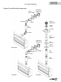
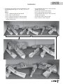
LIGHTING INSTRUCTIONS
1. STOP! Read the safety information above.
2. TO CLEAR ANY GAS, turn main valve off by pressing OFF (red dot) button on remote handset
(1).
• Wait fi ve (5) minutes to clear out any gas, then smell for gas, including near the fl oor. If you
smell gas, STOP! Follow “B” in the safety information above on this label. If you don’t smell
gas, go to the next step.
3. AUTOMATIC IGNITION: MAN-knob (2) in ON position. Ensure Flame Adjustment
knob (3) is set to lowest setting () (Fig. 1). Locate the pilot (Fig. 3.) inside of
fi rebox at left hand side.
• On the remote control handset, press the OFF button (red dot) and large fl ame
button () simultaneously; a short acoustic signal confi rms the start has begun.
• Further short acoustic signals indicate the ignition process is in progress.
• When the pilot is lit, the Flame Adjustment knob (3) will automatically rotate to
the highest setting.
• Press the small fl ame button () on the remote control handset to reduce the
fl ame height.
4. MANUAL IGNITION: MAN-knob (2) in MAN position (Fig. 2). With the window
off , locate the pilot (Fig. 3) inside of fi rebox at left hand side.
• Set Flame Adjustment knob (3) to the lowest setting ().
• Push down the metallic core (4) with a pen or similar instrument; this will establish
the pilot gas fl ow.
• Light gas at the pilot (5) with a match.
• Continue holding down metal core (4) for about 10 seconds; after release, pilot
should remain lit.
• If the pilot will not stay lit after several tries, turn the gas control knob (3) to OFF () and call your local
service technician or gas supplier.
• Reinstall the window and set the MAN-knob (2) to ON; turn Flame Adjustment knob (3) up () or down ()
manually or use the fl ame buttons ()() on the remote control handset to adjust the fl ame height.
TO TURN OFF GAS TO APPLIANCE
AUTOMATIC SHUT-OFF (using the remote control handset):
• Press and hold the small fl ame button () on the remote control handset to shut-off the main burner gas fl ow.
• Press OFF button (red dot) on remote handset to shut-off the appliance, including pilot fl ame.
Spark
Pilot
Fig 3
Fig 1
Fig 2
1
OFF
5
OWNER’S
INFORMATION

15
Servicing Your Fireplace
We recommend having your fi replace serviced every year. Contact your supplier quoting the model
number. It will be helpful if the appliance’s serial number can also be quoted. These numbers are
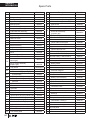
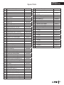
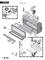
on the information card. The replacement parts are shown at the end of this manual. Please always
quote the part number and description when requesting spare parts.
Safe Operation List
To be performed by a qualifi ed technician only
1. Inspect and operate the pressure relief mechanism to verify relief mechanisms are free from
obstruction to operate. See Cleaning Your Fireplace: To refi t the window section of this manual.
2. Clean glass window with a suitable fi replace glass cleaner. Abrasive cleaners must not be used.
Be careful not to scratch the glass when cleaning. See Cleaning Your Fireplace section of this manual.
3. Inspect the operation of the fl ame safety system Pilot or Flame rectifi cation device.
4. Inspect and ensure the lighting of the main burner occurs within 4 seconds of the main gas valve
opening. Visual inspection should match that outlined in the appliance instruction manual. Inspect
primary air openings for blockage. See Checking Pilot and Burner Flame section of this manual.
5. Inspect condition of vent and vent terminal for sooting or obstruction and correct if present.
6. Vacuum and clean any debris in the fi rebox that is not supposed to be there.
7. Test and measure the fl ame failure response time of the fl ame safety system.
It must de-energize the safety shutoff in no more than 30 seconds.
8. Check all accessible gas-carrying tubes, connections, pipes and other components for leaks.
See Set up Gas Supply section of this manual.
Annual Inspection
In order to maintain the safe operation of your fi replace, contact your dealer to have a qualifi ed
technician go over the list below and make the necessary verifi cations at least once every year.
Maintaining Your Fireplace
OWNER’S
INFORMATION

16
WARNING
CHOKING HAZARD! Ensure that the fi replace
area is clear of fi rebed particles as these could
be ingested by small children. Vacuum thoroughly
around the fi replace area after cleaning.
WARNING
DO NOT TOUCH THE GLASS WHILE IT IS HOT!
Let the fi replace cool fi rst before cleaning it.
!
Spring Loaded
Window Levers
!
Cleaning Your Fireplace
Important - Glass cleaning - Mineral deposits
One of the by-products of the combustion process in
a gas appliance is a mineral which can show up as a
white fi lm on the ceramic glass of the viewing door.
The composition of the deposit varies with location and
time. It is believed to be associated with the varying
sulfur content of the gas. You may have the problem
intermittently.
We have consulted with ceramic glass manufacturers
and they cannot off er a defi nitive solution to this prob-
lem. Dealers have tried various cleaning products with
varying results. The following are recommendations
only and are not meant to guarantee results.
NOTE: This is a problem beyond Miles Industries’
control and is not covered under warranty.
• Clean the glass regularly as soon as you notice
the buildup (white fi lm). If the fi lm is left for a longer
period of time, it will etch into the glass. It is then
much harder, if not impossible, to remove.
• NEVER use an abrasive cleaner or ammonia-
based cleaner on the ceramic glass. Any
abrasion of the surface has the immediate eff ect of
compromising the strength of the glass. An emulsion
type cleaner is recommended.
• Use a soft damp cloth to apply the cleaner. Dry the
glass with a soft, dry, preferably cotton cloth. Most
paper towels and synthetic materials are abrasive to
ceramic glass and should be avoided.
• Our dealers have had good results from the
products listed below. We cannot, however,
guarantee the results of these products.
◊ Brasso, Polish Plus by Kelkem, Cook Top Clean
Creme by Elco, White Off by Rutland, Turtle Wax
Do not clean the glass while it is hot!
Always securely replace the window and the barrier
screen before lighting.
If broken, the glass pane may only be replaced
as a complete window unit as supplied by the
manufacturer.
If the barrier becomes damaged, the barrier shall
be replaced with the manufacturer’s barrier for this
appliance.
Clean the window panes following the guidelines in this
section.
Clean the steel trim with mild soap and warm water.
Any alcohol/solvent base cleaner will weaken the coat-
ing and damage it.
Clean the barrier screen dusting it with a soft brush.
Clean the fi rebox ceramic logs/rocks and walls dusting
them with a soft brush. Dust can also be removed from
the burner using a soft brush after removing the fuel
bed. When cleaning, make sure that no particles are
brushed into the slots of the burner.
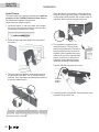
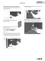
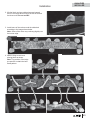
To remove the window for cleaning:
1. Remove the barrier screen.
2. Remove the side doors and the plinth.
3. Find the levers on each
side of the window
towards the top. Using
your fi nger, pull the
levers towards you and
unhook them from the
window frame brackets.
4. Gently pull the top of
the window outward.
5. Lift the window out of its bottom railing and set it
aside in a safe place to avoid damage.
Remove plinthRemove side doors
Maintaining Your Fireplace
OWNER’S
INFORMATION

17
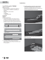
Window frame
Bottom railing
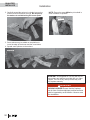
To refi t the window:
1. Place the window in its bottom railing. Ensure to
remove any vermiculite or glass particles in
the railing before installing the window.
2. Push the top
of the window
frame against
the fi rebox.
3. While you hold it, pull the side levers
back into the window brackets on each side.
4. Apply fi rm hand pressure around the window frame to
ensure the window is sealed tight against the fi rebox.
Hot Glass Warning Plate
5. If the Hot Glass Warning plate has been removed
from the front lower corner of the window,
reinstall it by sliding it between the glass and
the frame as indicated.
6. Reinstall the plinth and side doors.
7. Reinstall the barrier screen on the trim.
8. Verify that the screen is properly hooked to the trim
and secure.
1
2
3
WARNING
Failure to install the window correctly can
leak carbon monoxide, aff ect the performance
of the fi replace, damage components, cause
overheating resulting in dangerous conditions.
Damage caused by incorrect window installa-
tion is not covered by the Valor warranty.
!
DANGER
The window unit must be correctly installed,
fastened and sealed after servicing or serious
bodily injury and/or damage to the appliance
may result.
To ensure a safe operation:
• Double-check that the bottom of the window
frame is correctly installed in the bottom
support railing;
• Verify that the levers are hooked properly to
the window tabs then;
• Pull out the top of the window and release it
to insure the springs return it;
• Ensure the window is sealed before operation.
!
WARNING
FOR SAFETY PURPOSE, ensure the barrier
screen is re-installed on the fireplace after
maintenance.
!
Maintaining Your Fireplace
OWNER’S
INFORMATION

18
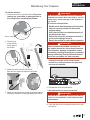
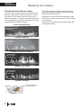
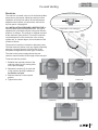
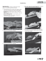
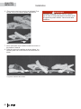
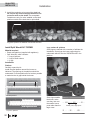
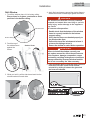
1705DWK—Driftwood
Correct Flame Appearance
1700DGM—Decorative Glass Murano
Pilot Flame can
be seen left of
the fi re bed
1714RSS—Rock & Shale
1700SWK—Split Wood
Pilot Flame can
be seen left of
the fi re bed
Pilot Flame can
be seen left of
the fi re bed
Pilot Flame Thermocouple Probe
must be in Flame
Checking Pilot and Burner Flames
A periodic check of the pilot and burner fl ames should
be made. Check after the fi re has been on for at least
30 minutes. The pilot fl ame must cover the tip of the
thermocouple probe. The main burner fl ame pattern will
vary from appliance to appliance depending on the type
of installation and climatic conditions.
The appliance area must always be kept clear and
free from combustible materials, gasoline and other
fl ammable vapors and liquids.
Inspect the vent terminal outdoors regularly to make
sure that snow, trees, bushes, leaves, or other objects
do not obstruct it.
Examine the vent system and terminal regularly. We
recommend annually.
Maintaining Your Fireplace
Pilot Flame can be seen
between the front and
rear left logs
OWNER’S
INFORMATION

19
WARNING
DO NOT ATTEMPT TO CHANGE THE BATTER-
IES WHILE THE FIREPLACE IS STILL HOT! Let
the fi replace cool fi rst before touching it.
CAUTION
DO NOT USE a screwdriver or other metallic object
to remove the batteries from the battery holder or
the handset! This could cause a short circuit.
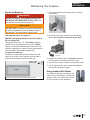
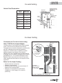
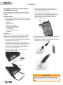
Battery holder
& wall switch
Fireplace
The battery holder is located beside the wall switch.
Disconnect
connector
!
Replacing Batteries
Low batteries signal: see page 12.
BEFORE changing the batteries, turn the fi replace
off (including pilot).
The appliance uses four 1.5 V AA alkaline batteries
located next to the wall switch and one 9 V alkaline
battery in its handset. Batteries should last one to two
seasons, depending on usage. Removing the batteries
in the off -season will extend the battery life.
To replace the batteries:
The battery compartment is located next to the wall
switch in the vicinity of the fi replace. Its front plate is
attached with magnets to the wall switch box.
1. Pull on the plate next to the wall switch to access
the batteries.
2. Disconnect the snap connector from the battery
holder. Do not pull the connector by the wire!
3. Replace the batteries with 4 AA alkaline batteries
orienting them as indicated inside the holder.
4. Reconnect the snap connector to the battery holder.
5. Put the battery holder back in its place beside the
wall switch and snap it in place.
Using Handset Wall Holder
Your fi replace equipment includes a wall
holder to store the handset. If it hasn’t be
installed, refer to the instructions further
on in this manual for the installation.
Maintaining Your Fireplace
OWNER’S
INFORMATION

20
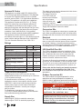
X
Model JN JP
Gas Natural Propane
Altitude (Ft.)* 0-4,500 feet*
Input Maximum (Btu/h) 36,000 34,000
Input Minimum (Btu/h) 19,000 21,000
Manifold Pressure (in w.c.) 4” 10”
Minimum Supply Pressure
(in w.c.) 5” 11”
Maximum Supply Pressure
(in w.c.) 10” 14”
Main Burner Injector Marking 1000 DMS#50
Pilot Injector Marking 51 30
Min. Rate By-Pass Screw 220 160
Specifi cations
Approval & Codes
This appliance is certifi ed to ANSI Z21.88-2016/CSA
2.33-2016 American National Standard / CSA Standard
for Vented Gas Fireplace Heaters for use in Canada
and USA, and to CGA 2.17-91 High Altitude Standard in
Canada. This appliance is for direct vent installations.
This appliance complies with CSA P.4.1-15 Testing
method for measuring annual fi replace effi ciencies.
The installation must conform to local codes or, in the
absence of local codes, with the National Fuel Gas Code,
ANSI Z223.1/NFPA 54 or the Natural Gas and Propane
Installation Code CAN/CGA-B149.1. Only qualifi ed
licensed or trained personnel should install this appliance.
This appliance must be electrically grounded in
accordance with local codes, or, in the absence of local
codes, with the National Electrical Code, ANSI/NFPA
70 or the Canadian Electrical Code, CSA C22.1.
Ratings
*High Altitude Installations
Input ratings are shown in BTU per hour and are
certifi ed without deration for elevations up to 4,500 feet
(1,370 m) above sea level.
For elevations above 4,500 feet (1,370 m) in USA,
installations must be in accordance with the current
ANSI Z223.1 and/or local codes having jurisdiction.
Heating value of gas in some areas is reduced to
compensate for elevation—consult your local gas
utility to confi rm.
For installations at elevations above 4,500 feet
(1,370 m) in Canada, please consult provincial and/or
local authorities having jurisdiction.
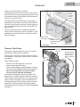
Supply Gas
Heater engine 1700JN is used with natural gas.
Heater engine 1700JP is used with propane gas.
This appliance is designed and approved as a
supplemental heater and provides the potential
for most energy conservation when used while
attended. The use of an alternate primary heat
source is advisable.
The supply pressure must be between the limits shown
in the Ratings section above.
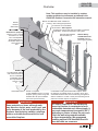
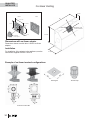
The supply connection
is 3/8” NPT male and
located on the left hand
side of the fi rebox.
A shut-off valve (not
supplied) is required
on the supply line to isolate the unit during service. See
Supply Gas Installation section for details.
Conversion Kits
The 1700 L2 is supplied as natural gas or propane gas
and is fi eld convertible between fuels. See instructions
packaged with the conversion kit for further information.
Electrical
The 1700 is designed to run on battery power and
does not require an electrical power source to operate
as a heater. However, it requires electrical power to
operate optional 1565LLK Linear Lighting Kit, 1595CFK
Circulating Fan Kit or 1270RBK Remote Blower Kit.
LDK HeatShift Duct Kit
The 1700J is designed to allow the installation of the
optional LDK HeatShift Duct Kit, a convection system
that redistributes the warm air fl ow away from the
fi replace opening to a more desirable location using
natural convection, without use of a fan.
The warm air fl ow may be relocated to a position higher
up the wall, out the sidewalls, or even to another room.
The result is much cooler wall temperatures above the
fi replace opening for locating televisions, artwork, etc.
Please note that the framing and mantel clearances
are aff ected by the installation of the LDK. Refer
to the installation manual packed with the kit for more
information.
Outdoor Conversion Kit
The 1700J models are supplied standard for indoor
applications and may be adapted for installation in
specifi c “outdoor” applications protected from weather as
defi ned in the GV60CKO outdoor conversion kit manual.
WARNING
Optional electrical accessories
ARE NOT ALLOWED when adapting
appliance for outdoor use.
!
QUALIFIED
INSTALLER
La page est en cours de chargement...
La page est en cours de chargement...
La page est en cours de chargement...
La page est en cours de chargement...
La page est en cours de chargement...
La page est en cours de chargement...
La page est en cours de chargement...
La page est en cours de chargement...
La page est en cours de chargement...
La page est en cours de chargement...
La page est en cours de chargement...
La page est en cours de chargement...
La page est en cours de chargement...
La page est en cours de chargement...
La page est en cours de chargement...
La page est en cours de chargement...
La page est en cours de chargement...
La page est en cours de chargement...
La page est en cours de chargement...
La page est en cours de chargement...
La page est en cours de chargement...
La page est en cours de chargement...
La page est en cours de chargement...
La page est en cours de chargement...
La page est en cours de chargement...
La page est en cours de chargement...
La page est en cours de chargement...
La page est en cours de chargement...
La page est en cours de chargement...
La page est en cours de chargement...
La page est en cours de chargement...
La page est en cours de chargement...
La page est en cours de chargement...
La page est en cours de chargement...
La page est en cours de chargement...
La page est en cours de chargement...
La page est en cours de chargement...
La page est en cours de chargement...
La page est en cours de chargement...
La page est en cours de chargement...
La page est en cours de chargement...
La page est en cours de chargement...
La page est en cours de chargement...
La page est en cours de chargement...
La page est en cours de chargement...
La page est en cours de chargement...
La page est en cours de chargement...
La page est en cours de chargement...
La page est en cours de chargement...
La page est en cours de chargement...
-
 1
1
-
 2
2
-
 3
3
-
 4
4
-
 5
5
-
 6
6
-
 7
7
-
 8
8
-
 9
9
-
 10
10
-
 11
11
-
 12
12
-
 13
13
-
 14
14
-
 15
15
-
 16
16
-
 17
17
-
 18
18
-
 19
19
-
 20
20
-
 21
21
-
 22
22
-
 23
23
-
 24
24
-
 25
25
-
 26
26
-
 27
27
-
 28
28
-
 29
29
-
 30
30
-
 31
31
-
 32
32
-
 33
33
-
 34
34
-
 35
35
-
 36
36
-
 37
37
-
 38
38
-
 39
39
-
 40
40
-
 41
41
-
 42
42
-
 43
43
-
 44
44
-
 45
45
-
 46
46
-
 47
47
-
 48
48
-
 49
49
-
 50
50
-
 51
51
-
 52
52
-
 53
53
-
 54
54
-
 55
55
-
 56
56
-
 57
57
-
 58
58
-
 59
59
-
 60
60
-
 61
61
-
 62
62
-
 63
63
-
 64
64
-
 65
65
-
 66
66
-
 67
67
-
 68
68
-
 69
69
-
 70
70


Valor 1700JN/JP Le manuel du propriétaire
- Taper
- Le manuel du propriétaire
dans d''autres langues
- English: Valor 1700JN/JP Owner's manual
Documents connexes
Autres documents
-
Danby DDEF03813BD13 Le manuel du propriétaire
-
-
Heat & Glo Tiara-I-B & Tiara-II-B Install Manual
-
Mitsubishi Electric MSZ-FE12NA Mode d'emploi
-
Bertazzoni REF36X Manuel utilisateur
-
LG TPNH488TLC1 Manuel utilisateur
-
Plymovent Limestone feeder Manuel utilisateur
-
Mitsubishi MFZ-KA12NA Le manuel du propriétaire
-
Saeco RI9829/11 Manuel utilisateur
-
GPS CI-2 Mode d'emploi