MINN KOTA 1866080 Le manuel du propriétaire
- Taper
- Le manuel du propriétaire

AUTOPILOT
MODE
SPOT-LOCK
CONSTANT
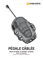
CORDED FOOT PEDAL
FOR ULTERRA® & RIPTIDE® ULTERRA
Owner's Manual
Compatible with Ulterra and Riptide Ulterra motors

CAUTION
For safety reasons, disconnect the motor from the battery/batteries when the motor is not in use or while the battery/batteries are being
charged. If the motor control is left on, and the Foot Pedal is accidentally engaged, and the propeller rotation is blocked, severe motor
damage can result.
WARNING
You are responsible for the safe and prudent operation of your vessel. We have designed your Foot Pedal to be an accurate and reliable
tool that will enhance boat operation and improve your ability to catch fish. This product does not relieve you from the responsibility
for safe operation of your boat. You must avoid hazards to navigation and always maintain a permanent watch so you can respond to
situations as they develop. You must always be prepared to regain manual control of your boat. Learn to operate your Foot Pedal in an
area free from hazards and obstacles.
WARNING
Practice proper ergonomics when operating the foot pedal to prevent injury.
2 | minnkotamotors.com ©2020 Johnson Outdoors Marine Electronics, Inc.
SAFETY CONSIDERATIONS

Before installing your Ulterra Foot Pedal, make sure that it is compatible with your motor. To review compatibility, please refer to the
"Compatibility" section in this manual. When placing the Ulterra Foot Pedal on your boat, select a location that will not obstruct boat
operation and that is appropriate for trolling motor operation. Place the Ulterra Foot Pedal in a foot pedal well on your boat if it has one,
or any location where it will be free from water and debris.
AA
22
BB
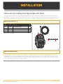
INSTALLATION PARTS LIST
MOUNTING CONSIDERATIONS
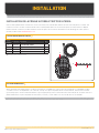
INSTALLING THE ULTERRA & RIPTIDE ULTERRA FOOT PEDAL
Your new Ulterra Foot Pedal accessory comes with everything you’ll need to directly install it on your trolling motor. These instructions
are intended to show how to install your new Ulterra Foot Pedal on an Ulterra or Riptide Ulterra trolling motor. Please review the parts list
and mounting considerations for installation prior to getting started. For additional product support, please visit minnkotamotors.com.
p Not shown on Parts Diagram.
Item /
Assembly Part # Description Qty.
A 2994741A FOOT PEDAL ASM, ULTERRA 1
B 2994859 BAG, ASY-TERROVA/V2, RUB BUMPERS 1
2 2325110 PAD, FOOT PEDAL 5
p2207110 INSTRC. SHEET,ULT. FT.PED.ACC. 1
minnkotamotors.com | 3
©2020 Johnson Outdoors Marine Electronics, Inc.
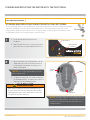
INSTALLATION

4 | minnkotamotors.com ©2020 Johnson Outdoors Marine Electronics, Inc.
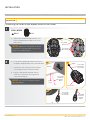
INSTALLATION
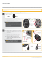
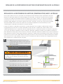
b. Locate the Foot Pedal Cord that exits the mount of
the Ulterra or Riptide Ulterra, next to the Power Cord.
c. Unscrew the caps at the end of the Foot Pedal
cords exiting the motor and the Foot Pedal.
d. Plug the cords together and make sure the
connection is secure. Be sure to tighten the
connector retaining nut.
AUTOPILOT
MODE
SPOT-LOCK
CONSTANT
NOTICE: The connectors are keyed to prevent
reversed installation.
Foot Pedal Foot Pedal
Cord from Cord from
Foot PedalFoot Pedal
CapCap
Foot PedalFoot Pedal
Foot Pedal Foot Pedal
Cord from Cord from
Foot PedalFoot Pedal
Foot Pedal Foot Pedal
Cord from Cord from
Trolling Trolling
MotorMotor
MountMount
Power Power
CordCord
INSTALLATION
Installing the Ulterra and Riptide Ulterra Foot Pedal
NOTICE: Adding the Foot Pedal pads is optional.
The pads are recommended when using the Foot
Pedal on non-carpeted surfaces.
Foot Pedal Foot Pedal
BottomBottom
Foot Pedal Foot Pedal
Pad PlacementPad Placement
ITEM(S) NEEDED
#2 x 5 #A x 1
a. Take the Foot Pedal (Item #A) and turn it over.
Put a Foot Pedal Pad (Item #2) in each of the
pad locations.
Foot Pedal Foot Pedal
Cord from Cord from
Trolling Trolling
MotorMotor
1
22b 2c
2d

minnkotamotors.com | 5
©2020 Johnson Outdoors Marine Electronics, Inc.
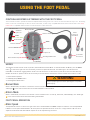
USING THE FOOT PEDAL
MODES
The Ulterra Foot Pedal has two modes of operation, Normal Mode and Ulterra Mode. To alternate between the Modes, press the MODE
button located on the right side of the Foot Pedal, just above the Speed Control knob. The amber light on the Indicator Panel
illuminates on and off when toggling between modes. The Indicator Panel is located on the top, left side of the Foot Pedal. Switching
between the modes of operation affects the functionality of the three buttons at the bottom of the Foot Pedal. These buttons include:
1. Steer Left/Trim Up button
2. Stow/Deploy/Prop ON/OFF button
3. Steer Right/Trim Down button
Normal Mode
When in Normal Mode, the buttons at the bottom of the Foot Pedal function to Steer Left, Steer Right, and turn the Prop ON/OFF. The
amber light MODE on the Indicator Panel will not be illuminated when in Normal Mode.
Ulterra Mode
When in Ulterra Mode, the buttons at the bottom of the Foot Pedal function to Trim Up, Trim Down, and Stow/Deploy. The amber light
MODE on the Indicator Panel will be illuminated during Ulterra Mode.
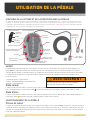
FOOT PEDAL OPERATION
Motor Speed
The Speed Control knob is located on the right side of the Foot Pedal between the MODE and Spot-Lock buttons. Turn the Speed Knob
forward to increase speed and backwards to decrease speed. The Speed Control knob can be set in a range from 0 to 10, and can be
adjusted in both Normal and Ulterra Modes. Speed can also be adjusted using the remote.
AutoPilot ON/OFFAutoPilot ON/OFF
ConstantConstant
Momentary ONMomentary ON
Spot-LockSpot-Lock
Speed ControlSpeed Control
Steer Left/Trim UpSteer Left/Trim Up Steer Right/Trim DownSteer Right/Trim Down
Stow/Deploy Stow/Deploy
Prop ON/OFFProp ON/OFF
MODEMODE
Heel/Toe SteeringHeel/Toe Steering Power Power
Connection Connection
from Motorfrom Motor
Foot Pedal Foot Pedal
ConnectionConnection
Indicator PanelIndicator Panel
Indicator PanelIndicator Panel
MODEMODE
Constant ONConstant ON
AutoPilot/ AutoPilot/
Spot-LockSpot-Lock
WARNING
Practice proper ergonomics when operating the foot pedal to
prevent injury.
CONTROLLING SPEED & STEERING WITH THE FOOT PEDAL
The Foot Pedal is used to operate the Ulterra or Riptide Ulterra trolling motor. The controls on the Foot Pedal are easy to use. The trolling
motor can also be controlled by an i-Pilot or i-Pilot Link remote, as well as any compatible Minn Kota remote. Please refer to the i-Pilot,
i-Pilot Link or compatible remote manual on how the remote controls the motor.

6 | minnkotamotors.com ©2020 Johnson Outdoors Marine Electronics, Inc.
FOOT PEDAL OPERATION
Spot-Lock
The Spot-Lock button is located on the bottom, right side of the Foot Pedal and is labeled with an anchor symbol. When the Spot-Lock
button is pressed, the location of the motor is recorded to a temporary Spot-Lock location. The blue light AUTOPILOT
SPOT-LOCK next to the Spot-Lock label
on the Indicator Panel is illuminated when Spot-Lock is engaged. To engage Spot-Lock press the Spot-Lock button, to disengage, press
the Spot-Lock button again. When engaging Spot-Lock, a tone will be emitted. When disengaging Spot-Lock with the Spot-Lock button,
no tone will be emitted. Steering the motor with the Foot Pedal or adjusting the speed using the Speed Knob will cancel Spot-Lock and
a High-Low, High-Low, High-Low tone will be emitted. Spot-Lock can be engaged in Normal and Ulterra Modes. Spot-Lock can also be
controlled with the remote. For more specific directions on how to use Spot-Lock, please refer to either the i-Pilot or i-Pilot Link Manual.
Steer Right/Steer Left
The Steer Right and Steer Left buttons are located at
the bottom of the Foot Pedal. They function to steer right and
left when the Foot Pedal is operating in Normal Mode. The
amber light MODE on the Indicator Panel will not be illuminated
when in Normal Mode. Holding the Steer Right or Steer Left
buttons down will continue to steer the motor to the left or
right. Small steering changes of less than one degree can be made by quickly tapping the Steer Right and Steer Left buttons.
Trim Down/Trim Up
The Trim Down and Trim Up buttons are located at the
bottom of the Foot Pedal. The Trim Down button trims the
motor down and the Trim Up button trims the motor up. Their
function is to trim the motor when the Foot Pedal is operating
in Ulterra Mode. The amber light MODE on the Indicator Panel will
be illuminated during Ulterra Mode.
Prop ON/OFF
The Prop ON/OFF button is located in the middle, at the bottom of the Foot Pedal. It functions to turn the Prop on and off when the
Foot Pedal is operating in Normal Mode. The amber light MODE on the Indicator Panel will not be illuminated when in Normal Mode. The
Prop will turn on when pressure is applied and turn off when pressure to the button is removed.
Stow/Deploy
The Stow/Deploy button is located in the middle, at the
bottom of the Foot Pedal. It functions to stow and deploy
the motor when the Foot Pedal is operating in Ulterra Mode.
The amber light MODE on the Indicator Panel will be illuminated
during Ulterra Mode. To stow the motor, when it is deployed,
press the Stow/Deploy button. To deploy the motor when it is stowed,
WARNING
When trimming the motor, keep fingers clear of all hinges, pivot
points and all moving parts. When stowing and deploying the
motor, ensure that it doesn’t contact the boat, trailer, or any
other obstruction.
WARNING
You are responsible for the safe and prudent operation of your vessel. We have designed Ulterra to be an accurate and reliable tool that
will enhance boat operation and improve your ability to catch fish. This product does not relieve you from the responsibility for safe
operation of your boat. You must avoid hazards to navigation and always maintain a permanent watch so you can respond to situations
as they develop. You must always be prepared to regain manual control of your boat. Learn to operate your Ulterra in an area free from
hazards and obstacles.
CAUTION
The steering system is designed to turn your motor 360
degrees. Be careful to avoid over-wrapping the Coil Cord around
the trolling motor Shaft.
WARNING
When stowing or deploying the motor, keep fingers clear of all
hinges, pivot points and all moving parts. When stowing and
deploying the motor, ensure that it doesn’t contact the boat,
trailer, or any other obstruction.

minnkotamotors.com | 7
©2020 Johnson Outdoors Marine Electronics, Inc.
FOOT PEDAL OPERATION
Constant
The Constant button is located on the left side of the Foot Pedal, towards the bottom, right below the AutoPilot button. It functions
to toggle the motor between Constant Motor Operation and Momentary Motor Operation. The green light CONSTANT
on the Indicator Panel will
be illuminated when the motor is in Constant Motor Operation. In Constant Mode, the propeller will continually run, regardless of whether
or not force is being applied to the Momentary button or Prop ON/OFF button. While in Constant Motor Operation, the propeller will run
continuously at the speed set by the Speed Control knob, or by the i-Pilot or i-Pilot Link remote.
If a propeller encounters an obstruction while either in Momentary or Constant Mode, while the propeller is running, the increased
electrical current being generated by the obstruction will signal the motor to decrease the power to the propeller to prevent damage. If
the current overload is detected for more than 20 seconds, the prop will be disabled to prevent damage to the motor. In this event, the
operator can turn the prop back on after being sure that the obstruction has been cleared.
AutoPilot
The AutoPilot button is located in the middle, on the left side of the Foot Pedal. Pressing the AutoPilot button toggles the feature on
and off. The red light AUTOPILOT
SPOT-LOCK on the Indicator Panel is illuminated when this feature is engaged. By default, AutoPilot Mode is determined
by the remote when AutoPilot is initiated from the Foot Pedal. AutoPilot can be used in both Standard and Ulterra Modes. AutoPilot
can also be controlled using the remote. For more specific directions on how to use AutoPilot, please refer to either the i-Pilot or i-Pilot
Link Manual.
Momentary
In Momentary Motor Operation, the propeller will only run while downward force is applied to the Momentary button. The Momentary
button is on the Toe End of the Heel/Toe Steering pedal. Applying downward pressure to the Momentary button will turn the propeller on.
The motor will then run at the speed set by the Speed Knob. Removing downward force to the Momentary button will turn the propeller
off. No indicator light is associated with the Momentary button. The Momentary button functions very similar to the Prop ON/OFF button,
but works in both Normal and Ulterra Modes.
Heel/Toe Steering
Push the Toe End of the Foot Pedal down to turn right and push
the Heel End of the Foot Pedal down to turn left. The position and
direction of the Control Head directly corresponds to the position of
the motor. You must use your foot on the pedal to control the steering
direction during manual operation. The direction of the motor can
also be controlled with the remote. Heel/Toe Steering functions the same Normal Mode and Ulterra Mode.
double press the Stow/Deploy button. When stowing and deploying the motor, it automatically disables the operational function of the
Foot Pedal or paired remote. "Motor Stowed" or "Motor Deploying" will be displayed on the screen of any applicable remote while the
specific action is occurring. The Prop is also disabled when the motor is stowed and deployed.
WARNING
When the motor is being transported, it is important to always stow the Motor and make sure it is locked in place. A secure stow holds
the motor in place during transportation when it is subject to high levels of shock and vibration. Failure to stow the motor may result in
injury or damage to the unit.
NOTICE: The motor will not auto correct to drive straight
when it encounters an obstruction.

8 | minnkotamotors.com ©2020 Johnson Outdoors Marine Electronics, Inc.
STOWING AND DEPLOYING THE MOTOR WITH THE FOOT PEDAL
c. On the Foot Pedal, press the Mode Button until the
amber LED in the center of the Indicator Panel on
the Foot Pedal is illuminated. This puts the Foot
Pedal in Ulterra Mode.
d.
Use the following procedure to stow and deploy the motor. Keep in mind that if your motor is stalling at a 45-degree
angle when attempting to stow, this indicates that batteries are too low to fully stow the motor. If this occurs,
reengage power, deploy the motor, trim the motor to its highest setting, and turn power off until batteries can be
recharged. Once batteries are charged, attempt to stow motor again.
NOTICE: You can only stow and deploy your motor
while in Ulterra mode.
NOTICE: The deploy sequence can be stopped at any time
pressing the stow/deploy button. The stow sequence can be
stopped at any time by pressing either trim button or the
stow/deploy button.
a. Locate the Indicator Panel at the base of
the Mount.
b. Make sure that the motor is on by checking that the
green LED next to the System Ready Indicator is on.
AUTOPILOT
SPOT-LOCK
MODE
CONSTANT
Stow/DeployStow/Deploy
MODEMODE
Indicator Indicator
PanelPanel
Power ButtonPower Button
System Ready System Ready
IndicatorIndicator
FOOT PEDAL ADJUSTMENTS
STOWING AND DEPLOYING THE MOTOR WITH THE FOOT PEDAL
1
2
WARNING
When stowing or deploying the motor, keep fingers clear of
all hinges, pivot points and all moving parts. When stowing
and deploying the motor, ensure that it doesn’t contact the
boat, trailer, or any other obstruction.
d. To deploy the motor, when it is stowed, double press
the Stow/Deploy button. To stow the motor, when it is
deployed, press the Stow/Deploy button.

minnkotamotors.com | 9
©2020 Johnson Outdoors Marine Electronics, Inc.
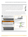
ADJUSTING THE DEPTH OF THE MOTOR (TRIM) WITH THE FOOT PEDAL
a. On the Foot Pedal, press the MODE button until the
amber LED in the center of the Indicator Panel on
the Foot Pedal is illuminated. This puts the Foot
Pedal in Ulterra Mode.
ADJUSTING THE DEPTH OF THE MOTOR (TRIM) WITH THE FOOT PEDAL
Once the boat is on the water, it may be necessary to adjust the trim of the lower unit up or down to achieve an optimum
depth for motor performance. When setting the depth of the motor, be sure the top of the motor is submerged at least
12” below the surface of the water to avoid churning or agitation of surface water. There will be times when you will need
to move your motor up or down depending on how your boat is responding. You can trim up to avoid hitting underwater
objects and you can trim down if your prop is coming out of the water. If your motor is equipped with either i-Pilot, or
i-Pilot Link, please refer to either the i-Pilot, or i-Pilot Link Owner’s Manual to learn how to adjust the trim with the
corresponding remote.
When trimming the motor using either a remote or the Foot Pedal, the motor is programmed to operate safely and limit prop rotation
when it is within certain limits. The prop will temporarily stop while trimming the motor and resume once trimming is stopped. Trim
limits are in place to avoid damage to the unit. An upper trim limit is set 12” from the bottom of the motor mount to the center of
the motor. A lower trim limit is set approximately 1.5” from the bottom of the control head to the trim housing. A prop lockout region,
defined as 17” from bottom of motor mount to center of motor, is used to eliminate the possibility of the motor contacting the boat hull.
All functions with the exception of manual steer and track record are canceled upon trimming into this region.
NOTICE: Please be sure the top of the motor
is submerged at least 12" below the surface of
the water to avoid churning or agitation of
surface water.
NOTICE: You can only trim your motor while in
Ulterra Mode.
PropellerPropeller
MotorMotor
12" Minimum Depth12" Minimum Depth
b. To trim the motor up, press the Trim Up button
located on the bottom, left of the Foot Pedal.
c. To trim the motor down, press the Trim Down button
located on the bottom, right of the Foot Pedal.
1
WARNING
When trimming the motor, keep fingers clear of all hinges,
pivot points and all moving parts.

10 | minnkotamotors.com ©2020 Johnson Outdoors Marine Electronics, Inc.
AUTOPILOT
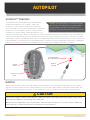
AUTOPILOTTM CONTROLS
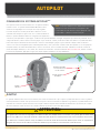
Your Ulterra may be purchased with factory installed AutoPilot.
The Minn Kota AutoPilot™ uses a magnetic compass and
microprocessor chip to keep the trolling motor pointed in the
direction you want to go. Each time the wind or water current moves
the boat off course, the AutoPilot senses the change and steers
itself back to the original heading. The AutoPilot direction is set
every time a steering change is made. To change direction, steer until the Control Head points to the desired course. The AutoPilot will
pull the bow of the boat around and correct automatically until the boat is moving in the direction you chose. If your motor is installed
with AutoPilot, it may be controlled with the Foot Pedal, or if equipped with CoPilot receiver, the CoPilot remote, or i-Pilot or i-Pilot Link
remote depending on your motor. Be sure to verify how AutoPilot is controlled on your motor if applicable. If your motor is installed with
either i-Pilot or i-Pilot Link, please refer to the applicable owner's manual online for additional information on AutoPilot.
AutoPilot
AutoPilot uses an internal compass to provide heading lock. When AutoPilot is on, it keeps the motor pointed in the same compass
direction. If a manual steering correction is made, AutoPilot locks onto the new compass heading to which the boat was steered. This
method of heading tracking does not take into account external forces such as a side wind or currents, which can allow side drift.
AutoPilot AutoPilot
HeadingHeading
Possible Deviation Possible Deviation
due to Wind/Currentdue to Wind/Current
CAUTION
This unit uses a magnetic compass to detect direction of travel. The compass can be adversely affected by magnets or large, ferrous
metal objects near (within 12” of) the trolling motor control head.
Obstructions on the propeller may cause excessive vibration of the motor head. This vibration can cause the compass to wander and
erratic steering to occur. Clear the obstruction to return the motor to normal operation.
AutoPilot AutoPilot
ButtonButton
Ulterra Foot Ulterra Foot
PedalPedal
NOTICE: The AutoPilot button on the Ulterra Foot Pedal
will only work if your Ulterra motor comes with AutoPilot
already installed on your motor. If your motor does not
already have this feature this button will be non-functioning.

minnkotamotors.com | 11
©2020 Johnson Outdoors Marine Electronics, Inc.
AUTOPILOT
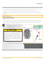
CONTROLLING AUTOPILOT
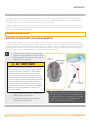
Toggle AutoPilot On/Off
a. While the motor is running, AutoPilot can be turned
on by pressing the AutoPilot button located on
the Foot Pedal, CoPilot remote, or using either the
i-Pilot or i-Pilot Link remote.
NOTICE: After steering to a new direction, there is a short
delay before the direction is locked in to allow the compass
to stabilize. When broad speed changes are made, the
AutoPilot heading may change slightly. This is normal.
When the AutoPilot is on and the trolling motor is pulled out of the water to the stow position, the steering motor will continue to run.
Turn off AutoPilot to stop the motor. If AutoPilot is left on, the steering motor will shut off automatically after 10 seconds. The motor
should not be stored in this condition for long periods as power is still being applied to all electronics. Always turn AutoPilot off and
disconnect your motor from the battery when storing your boat.
Possible Deviation Possible Deviation
due to Wind/Currentdue to Wind/Current
b. While AutoPilot is on, drive the boat as desired.
c. To turn AutoPilot off, press the AutoPilot button again.
CAUTION
When the AutoPilot is on and the trolling motor is pulled
out of the water to the stow position, the steering motor will
continue to run. Turn off the AutoPilot switch to stop the
motor. If the switch is left on, the steering motor will shut
off automatically after 10 seconds. The motor should not
be stored in this condition for long periods as power is still
being applied to all electronics. Always turn the Autopilot
switch off and disconnect your motor from the battery when
storing your boat.
AutoPilot AutoPilot
ButtonButton
Ulterra Ulterra
Foot Foot
PedalPedal
This unit has an automatic steering shutdown for safety. In conditions where an obstruction prevents the trolling motor from turning, or
in extremely windy conditions, the automatic steering may stop. Any steering input will reset the system to normal.
When AutoPilot is "on" and the trolling motor is pulled out of the water to the stow position, the steering motor will continue to run
until the motor is stowed properly. Once the motor is stowed properly, AutoPilot will turn "off" and the AutoPilot Indicator will no longer
be illuminated.
AutoPilot AutoPilot
HeadingHeading
1

12 | minnkotamotors.com ©2020 Johnson Outdoors Marine Electronics, Inc.
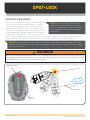
SPOT-LOCK
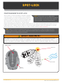
HOW SPOT-LOCK WORKS
Spot-Lock uses a single point of reference that is recorded when the
Spot-Lock button is pressed. The reference point is a set of GPS
coordinates that are captured at the location of the motor at the
moment the button is pressed. This point is recorded and can be
saved into one of the Spot-Lock memory locations. Spot-Lock works
by recognizing the GPS coordinates and will automatically navigate
the boat to keep it at the Spot-Lock location. If i-Pilot Link sees the
motor is not positioned at the Spot-Lock location, it will control motor speed and direction in an attempt to keep the motor on the
Spot-Lock. For more specific directions on how to use Spot-Lock, please refer to either the i-Pilot or i-Pilot Link Manual.
Spot-LockSpot-Lock
NOTICE: Spot-Lock is based on the location of the motor, not on the location or direction of the boat. Outside forces such as
wind and current will cause the boat to move. Spot-Lock will navigate to maintain the motor on the Spot-Lock location regardless
of the position of the boat.
Wind/CurrentWind/Current
WARNING
Watch for a turning propeller when working with Spot- Lock. The propeller will automatically turn on when Spot-Lock is engaged, even if
the engagement is accidental. A turning propeller can cause injury. The propeller will turn "on" for Spot-Lock and regardless of the Prop
Auto On setting used on the i-Pilot or i-Pilot Link navigational system.
NOTICE: The Spot-Lock button on the Ulterra Foot
Pedal will only work if your Ulterra motor comes with
Spot-Lock already installed on your motor. If your motor
does not already have this feature this button will be
non-functioning.
Ulterra Foot PedalUlterra Foot Pedal
Spot-Lock Spot-Lock
ButtonButton

minnkotamotors.com | 13
©2020 Johnson Outdoors Marine Electronics, Inc.
SPOT-LOCK
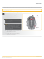
CONTROLLING SPOT-LOCK
Toggle Spot-Lock On/Off
a. While the motor is running, Spot-Lock can be
turned on by pressing the Spot-Lock button located
on the Foot Pedal, a Micro Remote remote, or using
either the i-Pilot or i-Pilot Link remote.
NOTICE: If the Spot-Lock button is accidentally
pressed, press the Spot-Lock button again to cancel
Spot-Lock.
NOTICE: Pressing any button on the foot pedal, or
manually steering the motor with the foot pedal will
disengage Spot-Lock. Manually steering or adjusting
the Prop Speed with the Remote will also cancel
Spot-Lock.
1
b. While AutoPilot is on, drive the boat as desired.
c. To turn AutoPilot off, press the AutoPilot button again.
Spot-Lock Spot-Lock
ButtonButton
Ulterra Ulterra
Foot PedalFoot Pedal

14 | minnkotamotors.com ©2020 Johnson Outdoors Marine Electronics, Inc.
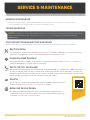
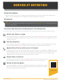
SERVICE & MAINTENANCE
GENERAL MAINTENANCE
• Keep the Foot Pedal well dry and clean. Debris that gets in the Foot Pedal can cause interference of pedal operation.
It is recommended to use compressed air to clean the foot pedal after each use.
NOTICE: For malfunctions, visit an Authorized Service Center. You can search for an Authorized Service Center in your area by
visiting our Authorized Service page, found online at minnkotamotors.com, or by calling our customer service number at
800-227-6433.
TROUBLESHOOTING
FOR FURTHER TROUBLESHOOTING AND REPAIR
We offer several options to help you troubleshoot and/or repair your product. Please read through the options listed below.
Buy Parts Online
You can buy parts on-line directly from our website at minnkotamotors.com. Orders confirmed by 12 noon central time will ship
same day if in stock. Orders after 12 noon central time will ship the next business day if in stock.
Frequently Asked Questions
We have FAQs available on our website to help answer all of your Minn Kota questions. Visit minnkotamotors.com and click on
“Frequently Asked Questions” to find an answer to your question.
Call Us (for U.S. and Canada)
Our consumer service representatives are available Monday – Friday between 7:00 a.m. – 4:30 p.m. CST at 800-227-6433. If you
are calling to order parts, please have the 11-character serial number from your product, specific part numbers, and credit card
information available. This will help expedite your call and allow us to provide you with the best consumer service possible. You can
reference the parts list located in your manual to identify the specific part numbers.
Email Us
You can email our consumer service department with questions regarding your Minn Kota products.
To email your question, visit minnkotamotors.com and click on “Support”.
Authorized Service Centers
Minn Kota has over 800 authorized service centers in the United States and Canada where you
can purchase parts or get your products repaired. Please visit our Authorized Service Center page
on our website to locate a service center in your area.
Scan to visit Minn
Kota service online.

minnkotamotors.com | 15
©2020 Johnson Outdoors Marine Electronics, Inc.
COMPLIANCE STATEMENTS
ENVIRONMENTAL COMPLIANCE STATEMENT
It is the intention of JOME to be a responsible corporate citizen, operating in compliance with known and applicable environmental
regulations, and a good neighbor in the communities where we make or sell our products.
WEEE DIRECTIVE
EU Directive 2002/96/EC “Waste of Electrical and Electronic Equipment Directive (WEEE)” impacts most distributors, sellers, and
manufacturers of consumer electronics in the European Union. The WEEE Directive requires the producer of consumer electronics to
take responsibility for the management of waste from their products to achieve environmentally responsible disposal during the product
life cycle.
WEEE compliance may not be required in your location for electrical & electronic equipment (EEE), nor may it be required for EEE
designed and intended as fi xed or temporary installation in transportation vehicles such as automobiles, aircraft, and boats. In some
European Union member states, these vehicles are considered outside of the scope of the Directive, and EEE for those applications can
be considered excluded from the WEEE Directive requirement.
This symbol (WEEE wheelie bin) on product indicates the product must not be disposed of with other household
refuse. It must be disposed of and collected for recycling and recovery of waste EEE. Johnson Outdoors Inc. will mark
all EEE products in accordance with the WEEE Directive. It is our goal to comply in the collection, treatment, recovery,
and environmentally sound disposal of those products; however, these requirements do vary within European Union
member states. For more information about where you should dispose of your waste equipment for recycling and
recovery and/or your European Union member state requirements, please contact your dealer or distributor from which
your product was purchased.
DISPOSAL
Minn Kota motors are not subject to the disposal regulations EAG-VO (electric devices directive) that implements the WEEE directive.
Nevertheless never dispose of your Minn Kota motor in a garbage bin but at the proper place of collection of your local town council.
Never dispose of battery in a garbage bin. Comply with the disposal directions of the manufacturer or his representative and dispose of
them at the proper place of collection of your local town council.

16 | minnkotamotors.com ©2020 Johnson Outdoors Marine Electronics, Inc.
COMPLIANCE STATEMENTS
FCC COMPLIANCE
This device complies with Part 15 of the FCC rules. Operation is subject to the following two conditions:
1. This device may not cause harmful interference.
2. This device must accept any interference that may be received, including interference that may cause undesired operation.
Changes or modifi cations not expressly approved by Johnson Outdoors Marine Electronics, Inc. could void the user’s authority to
operate this equipment.
INDUSTRY CANADA COMPLIANCE
This product meets the applicable Industry Canada technical specifi cations. Operation is subject to the following two conditions:
(1) this device may not cause interference, and (2) this device must accept any interference, including interference that may cause
undesired operation of the device.
Changes or modifi cations not expressly approved by Johnson Outdoors Marine Electronics, Inc. could void the user’s authority to
operate this equipment.
NOTICE: This equipment has been tested and found to comply with the limits for a Class B digital device, pursuant to part
15 of the FCC Rules. These limits are designed to provide reasonable protection against harmful interference in a residential
installation. This equipment generates, uses and can radiate radio frequency energy and, if not installed and used in accordance
with the instructions, may cause harmful interference to radio communications. However, there is no guarantee that interference
will not occur in a particular installation. If this equipment does cause harmful interference to radio or television reception, which
can be determined by turning the equipment off and on, the user is encouraged to try to correct the interference by one or more of the
following measures:
• Reorient or relocate the receiving antenna.
• Increase the separation between the equipment and receiver.
• Connect the equipment into an outlet on a circuit different from that to which the receiver is connected.
• Consult the dealer or an experienced radio/TV technician for help.
Ambient operating temperature range: -10C to 50C
Ambient operating humidity range: 5% to 95%
Maximum operating altitude: 10,000 feet
ENVIRONMENTAL RATINGS
CE MASTER USER MANUAL (FOR CE CERTIFIED MODELS)

minnkotamotors.com | 17
©2020 Johnson Outdoors Marine Electronics, Inc.
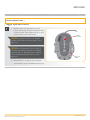
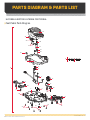
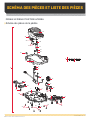
PARTS DIAGRAM & PARTS LIST
ULTERRA & RIPTIDE ULTERRA FOOT PEDAL
Foot Pedal Parts Diagram
A
B
38
42
40
44
46
14
12
28
26
8
4
16
30
32
18
6
20
18
58
58
10
54
56
22
24
52
36
34
50
48
18
60
2

18 | minnkotamotors.com ©2020 Johnson Outdoors Marine Electronics, Inc.
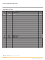
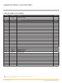
PARTS DIAGRAM & PARTS LIST
Foot Pedal Parts List
✖ This part is included in an assembly and cannot be ordered individually.
p Not shown on Parts Diagram.
Assembly Part # Description Quantity
A2994741A FOOT PEDAL ASSY, ULTERRA 1
B2994859 BAG ASY-TERROVA/V2,RUB.BUMPERS 1
Item Part # Description Quantity
22204500 BASE PLATE-ULTERRA / TERROVA 1
4✖PCB ASSY, ULTERRA 1
62373440 SCREW-#4-24 X 1/4 PHCR SS TY B 6
82372103 SCREW-#6-20 X 3/8 THD*(SS) 2
10 2302100 SCREW-#6-20 X 1/2 THD CUTS 2
12 2322900 STRAIN RELIEF, FOOT PEDAL 1
14 2372100 SCREW-#8-18 X 5/8 THD* (SS 2
16 2320100 KNOB-SPEED, FOOT PEDAL 1
18 2322704 SPRING, LARGE SHORT SS 7
20 2203710 BUTTON,LFT STR w/TRIM UP ARROW 1
22 2203711 BUTTON,RGT STR w/TRIM UP ARROW 1
24 2203715 BUTTON, MOMENTARY/STOW-DEPLOY 1
26 2323715 BUTTON,MOM/CON,FT PEDAL 1
28 2323725 BUTTON,AP,FT PEDAL 1
30 2203720 BUTTON, SPOT LOCK,ULTERRA/TRRV 1
32 2203725 BUTTON, MODE, ULTERRA 1
34 2200200 COVER,HEEL TOE FOOT PEDAL 1
36 2205605 DECAL, 3 INDICATORS, ULTERRA 1
38 2324401 PEDAL,HEEL/TOE FOOT PEDAL 1
40 2322714 SPRING (LEE #LC-029E-4-S) SS 1
42 2328600 FLEX FINGER, FOOT PEDAL 1
44 2321300 CLAMP-LEFT, FT PEDAL 1
46 2223430 SCREW-#8x3/4 PPH,TYPE 25,SS 2
48 2323710 BUTTON,MOM LEFT,FT PEDAL 1
50 2321300 CLAMP-LEFT, FT PEDAL 1
52 2223430 SCREW-#8x3/4 PPH,TYPE 25,SS 2
54 2322706 SPRING-BARREL SS 2
56 2323420 SCREW-#8-18 X 3/8" PFH SS TY B 2
58 2301310 SCREW-#8-18 X 1/2 (SS)* 11
60 2325110 PAD, FOOTPEDAL 5
p2207110 INSTRC. SHEET,ULT. FT.PED.ACC. 1

minnkotamotors.com | 19
©2020 Johnson Outdoors Marine Electronics, Inc.
NOTES

Minn Kota Consumer & Technical Service
Johnson Outdoors Marine Electronics, Inc.
PO Box 8129
Mankato, MN 56001
121 Power Drive
Mankato, MN 56001
Phone (800) 227-6433
Fax (800) 527-4464
minnkotamotors.com
©2020 Johnson Outdoors Marine Electronics, Inc.
All rights reserved.
Part #2207110 Rev C 09/20ECN 40110
• 60-Amp Circuit Breaker
• Mounting Brackets
• Stabilizer Kits
• Extension Handles
• Battery Connectors
• Battery Boxes
• Quick Connect Plugs
TALON SHALLOW WATER ANCHOR
Introducing the all-new, sleek redesigned Talon. Talon is the only shallow water anchor with up to 15’ of anchoring
depth, multiple anchoring modes, and control from the bow, transom, console, remote or mobile device.
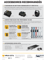
MINN KOTA ACCESSORIES
We offer a wide variety of trolling motor accessories, including:
UP TO 15’ DEEP
Control more water and catch
more fish with the first 15’
shallow water anchor.
BUILT-IN
WORK LIGHT
Lets you tie lines and work from
the transom any time of day —
or night. Includes both white
and blue LED lights with three
brightness settings.
MORE CONTROL
OPTIONS
• Control Panel
• Wireless Remote
• Mobile App
• Wireless Foot Switch
• Humminbird® Connectivity
• i-Pilot® &
i-Pilot LinkTM Remote
BLUETOOTH®
CONNECTIVITY
Lets you control Talon from your
mobile device and easily update
it. Also opens up communication
to other control options.
RECOMMENDED ACCESSORIES
ON-BOARD & PORTABLE BATTERY CHARGERS
Stop buying new batteries and start taking care of the ones you’ve got. Many chargers can actually damage your
battery over time – creating shorter run times and shorter overall life. Digitally controlled Minn Kota chargers are
designed to provide the fastest charge that protect and extend battery life.
MK210D M K110 P DMK212PC
La page est en cours de chargement...
La page est en cours de chargement...
La page est en cours de chargement...
La page est en cours de chargement...
La page est en cours de chargement...
La page est en cours de chargement...
La page est en cours de chargement...
La page est en cours de chargement...
La page est en cours de chargement...
La page est en cours de chargement...
La page est en cours de chargement...
La page est en cours de chargement...
La page est en cours de chargement...
La page est en cours de chargement...
La page est en cours de chargement...
La page est en cours de chargement...
La page est en cours de chargement...
La page est en cours de chargement...
La page est en cours de chargement...
La page est en cours de chargement...
-
 1
1
-
 2
2
-
 3
3
-
 4
4
-
 5
5
-
 6
6
-
 7
7
-
 8
8
-
 9
9
-
 10
10
-
 11
11
-
 12
12
-
 13
13
-
 14
14
-
 15
15
-
 16
16
-
 17
17
-
 18
18
-
 19
19
-
 20
20
-
 21
21
-
 22
22
-
 23
23
-
 24
24
-
 25
25
-
 26
26
-
 27
27
-
 28
28
-
 29
29
-
 30
30
-
 31
31
-
 32
32
-
 33
33
-
 34
34
-
 35
35
-
 36
36
-
 37
37
-
 38
38
-
 39
39
-
 40
40


MINN KOTA 1866080 Le manuel du propriétaire
- Taper
- Le manuel du propriétaire
dans d''autres langues
- English: MINN KOTA 1866080 Owner's manual
Documents connexes
-
MINN KOTA ULTERRA Mode d'emploi
-
MINN KOTA Riptide Ulterra Mode d'emploi
-
MINN KOTA 1866076 Le manuel du propriétaire
-
MINN KOTA POWERDRIVE V2 Manuel utilisateur
-
MINN KOTA PowerDrive Installation Instructions Manual
-
MINN KOTA PM6WRS Mode d'emploi
-
MINN KOTA i-Pilot Mode d'emploi
-
MINN KOTA 1810452 Mode d'emploi
-
MINN KOTA Edge Manuel utilisateur
-
