HME RT7000 REMOTE TRANSCEIVER Guide d'installation
- Taper
- Guide d'installation

Quick Reference Installation Guide
HM ELECTRONICS, INC.
2848 Whiptail Loop, Carlsbad, CA 92010 USA
Phone: 1-800-848-4468 Fax: 858-552-0172
Website: www.hme.com Email: [email protected]
HME# PUB - 000xx
Rev A 09/01/20
RT7000 REMOTE TRANSCEIVER
The RT7000 Remote Transceiver facilitates Base Station to Headset
communication. It uses a wired connection to the Base Station but
is wireless for Headset communication. Up to four RT7000s can be
connected to the Base Station for additional coverage.
TOOLS/EQUIPMENT REQUIRED
• Drill and drill bit set
• Screwdriver (Phillips #2), tape measure, pencil/maker
• Fish stick, cable ties, safety glasses, ladder
INSTALLATION, SETUP, AND OPERATION
1. Survey the premises to determine a good location to mount
the RT7000 (see Remote Transceiver RT7000 Notes on the next
page).
2. Once a good location is selected, route the Ethernet cable from
the Base Station to the RT7000 location.
3. Loosely mount the Remote Transceiver in an optimal location
(until range tested with a roving headset using the Installation
Wizard via the Base Station in step 5.
4. Connect the Ethernet cable to the RJ45 port on the rear of the
RT7000 (see Fig. 2) and the other end to one of the available
ports on the Base Station (see Fig. 4 and Table 1).
5. At the Base Station LOG IN to the system, go to SYSTEM, then
the ADVANCED tab and select “Installation” from the drop-
down menu. Tap the “Start Installation Wizard” button.
This opens the Installation Wizard as shown in Fig. 3.
Fig. 3
6. Follow the Transceiver Installation steps that follow. Once you
have used a headset in Reception Location Mode to walk the
premises to determine the mounting location is good, move
on to the next step. If the mounting location is not a good one,
move the Remote Transceiver to another location and repeat
steps 1 through 6, until a good location is found.
7. Drill two holes 6.625 inches (16.83 cm) apart along a horizontal
axis on the wall (avoid electrical or plumbing obstructions).
8. Install the provided hardware but do not tighten, leave a gap (~
¹/8th inch (3.2 mm)) between the screw heads and wall.
9. Align the RT7000 mounting holes with the two screws (Fig. 2).
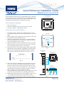
Fig. 1
Fig. 2
Fig. 4
1 2
3 4
RT7000 TRANSCEIVER
Front View
RT7000 TRANSCEIVER
Rear View
THIS SIDE UP
Mounting Holes
RJ45 Port
for Ethernet cable
1 2
3 4
RT7000 TRANSCEIVER
Front View
RT7000 TRANSCEIVER
Rear View
THIS SIDE UP
Mounting Holes
RJ45 Port
for Ethernet cable
NEXEO BASE STATION
PCBA (Partial)
Remote
XCVR 1
Remote
XCVR 2
Remote
XCVR 3
Remote
XCVR 4
Ethernet/
Network
Telephone
Interface
Timer Greet
Veh Detect 1
Timer Greet
Veh Detect 2
Veh Detect
Inputs
Alert
Inputs
Remote
Switches
Early
Warnings
Power
In
DC +
DC -
GND
Micro
USB
J200
J600
J201 J800 J801 J802
J805
J804
J803
J2003
J3000
J4500 J4501
J1400
J3200
J3400
J3600
J3800
1
1
1
1
1 1 1
1
1
1
1
Serial
Debug
USB
J?301
J?300
J1
PCBA
Side View Detail
Ethernet
(Network)
Remote
Module 1
Remote
Module 2
Remote
Module 3
Remote
Module 4
Power
Transceiver (x4)
1 2
3 4
Vertical Mount Only
(this way up)
REMOTE TRANSCEIVER
(RT7000)

© 2020 HM Electronics, Inc. All rights reserved.
2
Safety Notice
CAUTION: Wear proper eye, ear, and body protection when
grinding, drilling or working with tools. Follow the manufactur-
er’s safety information and operational instructions for tools
and materials. Be aware of your surroundings. Failure to heed such
precautions can cause injury and/or property damage.
Hygiene, Health, and Safety
Part of this installation requires working within a restaurant/store
where food is prepared, and customers dine. Please consult the
restaurant/store manager, standard operating procedures and any
additional restaurant safety/advisory protocols available before be-
ginning work within the restaurant/store. Follow the instructions and
guidelines provided.
10. Mount the RT7000 over the screw heads until flush
against the wall, then slide it down onto the screws
to secure it in place and tighten hardware.
11. The other end of the Ethernet cable is connected
to the Base Station (see Fig. 4 and the Table 1 for
connections).
12. The Base Station provides power to the RT7000. So
when connected, the center LED in the circle on the
front of the RT7000 turns on solid green.
13. The peripheral LED around the circle initially flash-
es as the RT7000 completes a scan of the environ-
ment. Once the scan is finished, this peripheral LED
also turns solid green.
Note: This LED also flashes blue when the firmware
is updating.
14. The RT7000 is now operational. The Base Station
HOME screen also provides a color-coded visual
status (see "Transceivers" status in Fig. 5).
Fig. 5
Tap "Transceivers" on the HOME screen for more details
(see Fig. 6).
Fig. 6
Remote Transceiver (RT7000) Notes:
• Mount the transceiver high in a central location to
headset usage.
• Maximize line of sight between the transceiver and
headsets in an area free from obstructions and
equipment/materials that can interfere with signal
propagation. These include walls, large metal ap-
pliances, hoods, and backsplashes, etc.
• Mount the transceiver vertically on a wall in the
upright position (see arrow on Transceiver rear). Do
NOT mount horizontally such as on a ceiling, this
will reduce the transceiver’s range.
• Signal propagation is strongest directly in front of
the Transceiver and then to the sides.
• The RT7000 uses an Ethernet (Cat5 or Cat6) cable.
Do not exceed 1000’ (304 m).
• Large premises may require more than one Trans-
ceiver. Up to four Transceivers are supported by
one Base Station.
• Once connected to the Base Station, the LED in
the middle of the circle on the
transceiver front illuminates to
indicate it is turned on. One of
the outer LEDs (numbered 1 to
4) around the circle also turns
on (depending on which port the
Transceiver is connected to on
the Base Station, see Fig. 7). This
outer LED will initially flash as the Transceiver scans
for available channels before turning solid green
once a channel is found (on the Base Station HOME
screen, the "Transceivers" indicator is yellow while
scanning before turning green).
Base Station RT7000 Ports
Connector #Label To
J3200
J3400*
J3600*
J3800*
Remote XCVR 1**
Remote XCVR 2**
Remote XCVR 3**
Remote XCVR 4**
First RT7000
Second RT7000
Third RT7000
Fouth RT7000
Table 1
* Only used if more than one RT7000 is required.
** LEDs (1 - 4) on the RT7000 Front (Fig. 7) correspond to the Remote
XCVR port number on the Base Station (Table 1 label).
1 2
3 4
HM ELECTRONICS, INC.
2848 Whiptail Loop, Carlsbad, CA 92010 USA
Phone: 1-800-848-4468
Fax: 858-552-0172
Website: www.hme.com
Email: [email protected]
The HME logo and product names are regis-
tered trademarks of HM Electronics, Inc.
A copy of this guide and additional information
can be found by scanning this QR code.
Fig. 7

© 2020 HM Electronics, Inc. All rights reserved. 3
REGULATORY COMPLIANCE
Applicant Name: HM Electronics, Inc.
Applicant Address: 2484 Whiptail Loop, Carlsbad CA 92010, United States
Manufacturer Name: HM Electronics, Inc.
Manufacturer Address: 2484 Whiptail Loop, Carlsbad CA 92010, United States
Country of Origin: USA
Brand: HME
Caution: All products are compliant with regulatory requirements detailed in this document when the user follows
all installation instructions and operating conditions per HME specifications.
Caution: Use of accessories and peripherals other than those recommended by HME may void the product's com-
pliance as well as the user's authority to operate the equipment.
Caution: All products are designed for use with the standard, integral or dedicated (external) antenna(s) that are
shipped together with the equipment. Any product changes or modifications will invalidate all applicable regulatory
certifications and approvals.
Caution: The use of software or firmware not supported/provided by HME products may result that the equipment is
no longer compliant with the regulatory requirements.
FCC NOTICE
This device complies with Part 15 of the FCC rules. Operation is subject to the following two conditions: (1) This
device may not cause harmful interference, and (2) This device must accept any interference received, including
interference that may cause undesired operation.
NOTE: This equipment has been tested and found to comply with the limits for a Class A digital device, pursuant to
Part 15 of the FCC rules. These limits are designed to provide reasonable protection against harmful interference
when the equipment is operated in a commercial environment. This equipment generates, uses and can radiate ra-
dio frequency energy and, if not installed and used in accordance with the instruction manual, may cause harmful
interference to radio communication. Operation of this equipment in a residential area is likely to cause harmful
interference, in which case the user will be required to correct the interference at his own expense.
Changes or modifications not expressly approved by HME could void the user’s authority to operate this equipment.
User Restriction in the 5Ghz band: The device for the band 5150-5250MHz is only for indoor
usage to reduce potential for harmful interference to co-channel mobile satellite systems.
FCC/IC/EC RF EXPOSURE WARNING
This product complies with FCC/IC/EC radiation exposure limits set forth for an uncontrolled environment.
Produits HME sont conformes aux limites IC d'exposition aux rayonnements définies pour un environnement non
contrôlé.
This product may not be co-located or operated in conjunction with any other antenna or transmitter.
Cet appareil et son antenne (s) ne doit pas être co-localisés ou fonctionnement en association avec une autre an-
tenne ou transmetteur.
To comply with FCC/IC/EC RF exposure requirements, this unit must be installed and operate at least 20 cm (8
inches) from any person.
Produits HME doivent être installés et utilisés avec distance minimum de 20cm entre le radiateur et votre corps.

© 2020 HM Electronics, Inc. All rights reserved.
4
INDUSTRY CANADA COMPLIANCE STATEMENT
Avis de conformité à la réglementation d'Industrie Canada
Cet appareil est conforme aux CNR d’Industrie Canada applicables aux appareils radio exempts de licence. L’ex-
ploitation est soumise aux deux conditions suivantes:
(1) cet appareil ne doit pas provoquer d’interféence, et
(2) cet appareil doit accepter toute interféence radioéectrique subie, mêe si l’interféence est susceptible d’en com-
promettre le fonctionnement.
Cet éetteur exempt de licence est éuipéd’une antenne intéré. Cet éetteur exempt de licence n’est pas autoriséà-
fonctionner avec une autre antenne.
Cet appareil et son antenne (s) ne doit pas être co-localisés ou fonctionnement en association avec une autre an-
tenne ou transmetteur.
Cet appareil numérique de la class[A] est conforme à la norme NMB-003 du Canada.
This Class[A] digital device complies with Canadian ICES-003.
Restrictions d'utilisation dans la bande 5 GHz: L’appareil pour la bande de 5150 a 5250MHz est concupour
usage a l’interieur seulement afin de reduire le potentiel d interferences pour les systemes mobiles par satellite qui
utilisent le meme canal.
User Restriction in the 5Ghz band: The device for the band 5150-5250MHz is only for indoor usage to reduce
potential for harmful interference to co-channel mobile satellite systems.
Jusqu’a nouvel ordre, les appareils faisant l’objet de la presente section ne doivent pas transmettre dans la bande
5600-5650 MHz, afin que les radars meteorologiques d’Environnement Canada fonctionnant dans cette bande
soient proteges.
Until further notice, devices subject to this Section shall not be capable of transmitting in the band 5600-5650MHz,
so that environmental weather radars operating in this band are protected.
KOREAN NOTICE
KCC 2.4Ghz and 5725-5850MHz warning: Life-related safety services cannot be provided because the radio
equipment may have radio interference.
AUSTRALIA COMPLIANCE STATEMENT
User Restriction in the 5Ghz band: This device is restricted to indoor use only when operating in 5150-5350MHz.
Until further notice, devices subject to this Section shall not be capable of transmitting in the band 5600-5650MHz,
so that environmental weather radars operating in this band are protected.

© 2020 HM Electronics, Inc. All rights reserved. 5
NEW ZEALAND COMPLIANCE STATEMENT
User Restriction in the 5Ghz band: This device is restricted to indoor use only when operating in 5150-
5250MHz.
EUROPEAN UNION (CE MARK)
The CE marking indicates compliance with the following directives and standards, whenever applicable to the prod-
uct in question.
Directives:
- Radio Equipment Directive 2014/53/EU
- Electromagnetic Compatibility Directive 2014/30/EU
- Low Voltage Directive 2014/35/EU
- RoHS Directive 2011/65/EU and 2015/863/EU
Standards:
- EN55022/EN55032
- EN55024/ EN55035
- IEC/EN62368-1
- EN300328
- EN301893
- EN301489
- EN50581
Warning: This is a Class A product. In a domestic environment this product may cause radio interference in which
case the user may be required to take adequate measures.
User Restriction in the 5Ghz band: This device is restricted to indoor use only when operating in 5150-5350MHz
for below EU member states.
Caution: Although Europe allows 5600-5650Mhz band, these DFS channels 120, 124 and 128 must perform a 10
minutes radar scanning (also known as CAC - Channel Availability Check) before becoming an operating channel.
WASTE ELECTRICAL AND ELECTRONIC EQUIPMENT (WEEE)
The European Union (EU) WEEE Directive (2012/19/EU) places an obligation on producers (manufacturers, dis-
tributors and/or retailers) to take-back electronic products at the end of their useful life. The WEEE Directive covers

© 2020 HM Electronics, Inc. All rights reserved.
6
most HME products being sold into the EU as of August 13, 2005. Manufacturers, distributors and retailers are
obliged to finance the costs of recovery from municipal collection points, reuse, and recycling of specified percent-
ages per the WEEE requirements.
INSTRUCTIONS FOR DISPOSAL OF WEEE BY USERS IN THE EUROPEAN UNION
The symbol shown below is on the product or on its packaging which indicates that this product was put on the
market after August 13, 2005 and must not be disposed of with other waste. Instead, it is the user’s responsibility
to dispose of the user’s waste equipment by handing it over to a designated collection point for the recycling of
WEEE. The separate collection and recycling of waste equipment at the time of disposal will help to conserve natu-
ral resources and ensure that it is recycled in a manner that protects human health and the environment. For more
information about where you can drop off your waste equipment for recycling, please contact your local authority,
your household waste disposal service or the seller from whom you purchased the product.
-
 1
1
-
 2
2
-
 3
3
-
 4
4
-
 5
5
-
 6
6


HME RT7000 REMOTE TRANSCEIVER Guide d'installation
- Taper
- Guide d'installation
dans d''autres langues
Documents connexes
-
HME NEXEO|HDX Crew Communication Platform Guide d'installation
-
-
HME HS7000 Guide d'installation
-
HME 7001 Guide d'installation
-
-
HME AC70 Mode d'emploi
-
HME ZOOM Nitro Mode d'emploi
-
-
-