
HME# 400G793
Rev A 9/23/19
HM ELECTRONICS, INC.
2848 Whiptail Loop, Carlsbad, CA 92010 USA
Phone: 1-800-848-4468 Fax: 858-552-0172
Website: www.hme.com Email: [email protected]
VDB103
VDB103R
Vehicle Detector Board
Installation Instructions


TABLE OF CONTENTS
Regulatory Label Placement.....................................................1
VDB103/VDB103R Theory of Operation .......................................................... 2
Loop Failure and Interference .................................................................. 2
ESD Handling Instructions..................................................................... 2
Installation .................................................................................. 3
Dip Switch Settings........................................................................... 4
Troubleshooting ............................................................................. 5
Reset Procedure ............................................................................. 5
Detector Function . . . . . . . . . . . . . . . . . . . . . . . . . . . . . . . . . . . . . . . . . . . . . . . . . . . . . . . . . . . . . . . . . . . . . . . . . . . . 5
Self Diagnostics ............................................................................. 6
Regulatory Compliance Approvals .............................................................. 7
© 2019 HM Electronics, Inc.
The HME logo and product names are registered trademarks of HM Electronics, Inc. All rights reserved.
US Patent 9,885,799


1
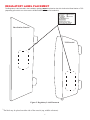
REGULATORY LABEL PLACEMENT
The Regulatory Label included in the installation package must be placed on the side of either the Base Station or TSP
(depending upon which one of the two the VDB103/VDB103R board is installed in).
TSP Console*
Base Station Console*
*
The label may be placed on either side of the console (top, middle or bottom).
Figure 2. Regulatory Label Placement

2
VDB103/VDB103R THEORY OF OPERATION
The VDB103/VDB103R uses digital signal processing techniques to assess parameters inherent to inductive ground loops
in order to evaluate loop status and signal vehicle detection. As a loop operator, this technology gives you the benet of
understanding the quality of your loop in real-time with advanced foresight and warning of deteriorating conditions.
This allows preventative measures to be taken to avoid down time and situations in which your drive-thru technologies
and services are hindered or incapacitated due to a failed or failing loop. While these events are unlikely, the advanced
warning system of the VDB103/VDB103R offers peace of mind that drive-thru operations will continue to be uninterrupted.
Through continuous measurement of the inductive ground loop, the VDB103/VDB103R determines the inherent electrical
characteristics of the loop which include: loop condition, connection quality, and the inductance of the loop. These three
parameters are evaluated to determine the Loop Status as seen in Figure 4, page 6. In the case of a deteriorating loop,
the VDB103/VDB103R offers insight into the underlying cause and the course of action to help troubleshoot your issue.
The vehicle detection portion of the VDB103/VDB103R operates through analysis of loop response to a stimulus provided
by the detector, which characterizes the inductance of a loop. The presence of a vehicle over the loop electromagnetically
interacts with the loop causing a change in inductance. The VDB103/VDB103R monitors these small inductance changes
in order to signal vehicle detection.
LOOP FAILURE AND INTERFERENCE
Inductive ground loops may eventually fail. The VDB103/VDB103R can remove the surprise of failure from operation
and allows you to prepare for such an event well in advance. Loop failure is the result of damage to the loop which can
include, but is not limited to: damage to area surrounding loop, severed loop or lead in wires, or insulation damage as a
result of aging and other environmental factors.
In addition, deteriorating connections between the loop and the VDB103/VDB103R can cause detection failure even
though the loop itself is in good condition.
The VDB103/VDB103R is essentially a large metal detector. Do not install the loop over any metallic object, surface,
or area. This includes installing the loop over rebar. Failure to adhere to this installation recommendation will result in
unexpected loop behavior.
ESD HANDLING INSTRUCTIONS
CAUTION
Contains parts and assemblies susceptible
to damage by Electrostatic Discharge (ESD)
This device is sensitive to electrostatic discharge and should be installed by personnel trained in ESD awareness. Proper
handling procedures include wearing anti-static wrist straps.

3
INSTALLATION
If you’re replacing an existing board, begin at Step 1. If no previous VDB103/VDB103R board exists, begin at Step 6.
1. When handling the VDB103/VDB103R, wear an anti-static wrist strap to avoid electrical damage to the board.
2. Disconnect the drive-thru audio or timer system power adapter from its electrical outlet.
3. Disconnect the loop cable from TB1 on the existing board to be replaced.
4. Disconnect interconnect cable from its connector (P1) on the base station or control unit circuit board. Note the connector and
its location.
5. Remove the existing board by lifting it off the plastic standoffs that hold it in place.
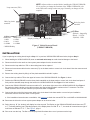
6. Connect the loop cable to TB1 at the upper left corner of the VDB103/VDB103R. See Figure 1, above.
7. Position the VDB103/VDB103R over the three plastic standoffs on the base station or control unit circuit board and press it
rmly until the standoffs snap through the holes on the VDB103/VDB103R. See Figure 1 for hole locations.
8. Connect the VDB103/VDB103R interconnect cable to P1, at the lower right corner of the VDB103/VDB103R. See Figure 1.
Be certain the plastic catches on the cable connector are aligned with the plastic catches on the P1 connector. The color-
coded connector wires must also match the pin positions shown on Figure 1.
9. Connect the other end of the interconnect cable to the circuit board in the base station or control unit per installation
instructions from the drive-thru audio or timer system.
h If the installation instructions are not available, visit hme.com to obtain the manual PDF le or call HME at 1-800-848-4468.
10. Reconnect the drive-thru or timer system power adapter to its electrical outlet.
11. During boot up, “b” (for ‘booting’) will display for a few seconds. The Display on the VDB103/VDB103R should then read “0”
or “1 ”, indicating that the loop is signaling properly. If the Display does not read “0” or “1 ”, be certain all connections are tight. If
it still does not indicate “0” or “1 ”, see Figure 4, page 6.
12. Drive a car onto the loop. The Dot on the Display should illuminate when a car is present over the loop.
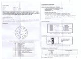
P1 Pins:
3 (black) - Output/Sig
2 (red) - +12VDC
1 (shield) - GND
Holes for plastic
standoffs
Loop connector (TB1)
Display (reading “
0”)
Display Dot
Figure 1. Vehicle Detector Board
(VDB103/VDB103R)
NOTE: Adjust switches as needed before installing the VDB103/VDB103R.
If it is necessary to change the functions of the VDB103/VDB103R, refer
to the DIP switch settings on the next page. Normally, no changes will be
required.
1 2 3
Holes for plastic
standoffs
J1 Pins*
Relay out 1
1 - NO1
2 - NC1
3 - COM1
Relay out 2
4 - NO2
5 - NC2
6 - COM2
* VDB103R Only

4
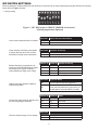
DIP SWITCH SETTINGS
Before installing the VDB103/VDB103R, the following six functions can be set by switching/moving the switches as indicated
below. Refer to Figure 3, below.
* = factory setting
Figure 3. SW1 DIP switch on VDB103/VDB103R circuit board
(Default pin positions displayed)
Switch #1 Vehicle Presence Auto Reset
OFF No Timeout
ON 20 minute timeout for vehicle presence *
Switch #2 Detection Sensitivity
OFF Normal Sensitivity *
ON Low Sensitivity
Switch #3 Switch #4 Release Sensitivity
OFF OFF Low
OFF ON Medium *
ON OFF High
ON ON Extra High
Switch #5 Diagnostic Mode
OFF Normal VDB103/VDB103R Operation *
ON
Detection is Suspended - DSP rmware
scrolls, and car presence is cycled every 10
seconds (On 10 seconds, Off 10 seconds)
Switch #6 Switch #7 Delay
OFF OFF 6 seconds
OFF ON 4 seconds
ON OFF 2 seconds
ON ON 0 seconds *
Switch #8
OFF Daily Log
ON Weekly Log *
Clears vehicle detection after 20 minutes.
Lower detection sensitivity corresponds
to slower detection at the risk of small
uctuations causing missed detections.
Release Sensitivity correlates to how
quickly the VDB103/VDB103R will signal
vehicle departure (higher sensitivity
means departures trigger more easily).
Veries connection between VDB103/
VDB103R and Base.
Controls the delay between detection and
the actual signaling of detection.
ON is the default setting. Do not change.

5
TROUBLESHOOTING
Release Sensitivity
h Set to Low if multiple detections or dropouts occur frequently at Normal.
h Set to High or Extra High to compensate for improperly positioned loops where run-ons occur.
h Set as low as practical. Check for run-ons or dropouts and set for best operation.
RESET PROCEDURE
If the detector is stuck indicating a vehicle present continuously or is otherwise unresponsive, follow the reset steps below:
With no vehicle present over the vehicle detector loop:
h Press and hold the Reset switch in the base station or timer for 1 second and then release. The VDB103/VDB103R display
will go blank for a few seconds and then should show “b” for a second or two.
h Reset is complete when the VDB103/VDB103R display shows a code other than “b” or “F”.
DETECTOR FUNCTION
To verify proper detector board function, disconnect one of the wires to the detector loop and verify that the board display changes
to “d”. Then reconnect the wire and the display should change back to one of the normal codes. If the display was originally
showing “d”, short the two loop terminals and watch for the display to change to “C”.

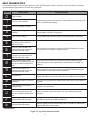
6
Display Description Troubleshooting
0
Loop is healthy
If experiencing problems with detection, reassess DIP switch settings or call
HME* for guidance with settings.
1
Loop is in good condition
2
Loop is in moderate condition
3
Loop is approaching a critical
condition
Severe weather may exacerbate problem. Loop replacement is
recommended. Call HME* for guidance
4
Loop is close to failure Severe weather may make the loop fail. Loop replacement is necessary.
5
Loop is healthy, but connection
from the loop to the VDB103/
VDB103R is bad
Check electrical connections to loop and to VDB103/VDB103R as well as
any cable splices. Call HME* if problem persists.
6
Loop is in good condition, but
connection from the loop to the
VDB103/VDB103R is bad
7
Loop is in moderate condition, but
connection from the loop to the
VDB103/VDB103R is bad
8
Loop is approaching a critical
condition, but connection from the
loop to the VDB103/VDB103R is
bad
Check electrical connections to loop and to VDB103/VDB103R as well
as any cable splices. Loop replacement is recommended. Call HME* for
guidance.
9
Loop is close to failure, but
connection from the loop to the
VDB103/VDB103R is bad
Check electrical connections to loop and to VDB103/VDB103R as well as
any cable splices. Loop replacement is necessary.
C
Loop Shorted
Disconnect loop from lead-in cable outside the building and re check. If still
shorted, the cable is bad. If open (code “d”), loop replacement is indicated.
d
Loop disconnected from VDB103/
VDB103R
Check electrical connections at VDB103/VDB103R, loop, and any splices in
the cable.
L
Loop inductance is outside of
operable range
Schedule loop replacement.
U
Loop inductance is outside of
range, and connection from the
loop to the VDB103/VDB103R is
bad
Check all electrical connections and re test. Loop replacement may be
necessary.
F
VDB103/VDB103R has failed Call HME* for replacement VDB103/VDB103R.
b
VDB103/VDB103R booting
Normal to appear for a few seconds after reset. Call HME* for replacement
VDB103/VDB103R if code persists.
*1-800-848-4468
Figure 4. Loop Status Indication Table
SELF DIAGNOSTICS
If an abnormal condition with the loop or detector occurs, the LED display will show a number or letter (see below). Follow the
recommendations appropriate for the code that is displayed.

7
REGULATORY COMPLIANCE APPROVALS
HME is committed to compliance with the laws and regulations of each country where HME markets the product below.
Applicant Name : HM Electronics, Inc.
Applicant Address : 2848 Whiptail Loop, Carlsbad, CA 92010 USA
Manufacturer Name : HM Electronics, Inc.
Manufacturer Address : 2848 Whiptail Loop, Carlsbad, CA 92010 USA
Country of Origin : USA
Brand : HME
Product Name : Vehicle Detection Board
Product Regulatory Model Number : RFM100
This document was prepared in the English language. In case this document is translated into another language and a discrepancy arises between languages,
the English version shall prevail as being the version which best expresses the intent of the parties. Any notice or communication given in conjunction with this
document must include an English version.
Caution: All products are compliant with regulatory requirements detailed in this document when the user follows all the installation instructions and
operating conditions per HME specications.
Caution: Product modications not expressly approved by the party responsible for compliance can void the user’s authority to operate the equipment.
Cause: Use of accessories and peripherals other than those recommended by HME may void the product’s compliance as well as the user’s authority to
operate the equipment.
Caution: Operating or storing the product outside the specied temperature range of 0-50º Celsius can damage it.
RF Exposure Notice
This module transmitter complies with radiation exposure limits set forth for the general public (uncontrolled environment) per FCC, IC and EC rules and
guidelines. This module transmitter must be installed to operate with a minimum separation distance of 7.87 inches (20 cm) from all persons. To avoid the
possibility of exceeding radio frequency exposure limits, human proximity to the antenna shall not be less than 20cm.
Avis d’exposition RF
Ce module émetteur est conforme aux limites d’exposition aux radiations énoncées pour le grand public (environnement incontrôlé) selon les règles et directives
FCC, IC et EC. Ce module émetteur doit être installé de façon à fonctionner avec une distance de séparation minimale de 20 cm (7,87 pouces) de toutes
personnes. Pour éviter la possibilité de dépasser les limites d’exposition aux fréquences radio, la proximité humaine de l’antenne ne doit pas dépasser 20 cm.
US Compliance Notice
This device complies with part 15 of the FCC Rules. Operation is subject to the following two conditions: (1) This device may not cause harmful interference, and
(2) this device must accept any interference received, including interference that may cause undesired operation.
Note: This equipment has been tested and found to comply with the limits for a Class A digital device, pursuant to part 15 of the FCC Rules. These limits are
designed to provide reasonable protection against harmful interference when the equipment is operated in a commercial environment. This equipment generates,
uses, and can radiate radio frequency energy and, if not installed and used in accordance with the instruction manual, may cause harmful interference to radio
communications. Operation of this equipment in a residential area is likely to cause harmful interference in which case the user will be required to correct the
interference at his own expense.
Model RFM100 is a module transmitter that is installed inside a host or nished product. It was certied with single modular approval per Federal Communications
Commission (FCC) CFR47 Telecommunications, Part 15.212 under Subpart C Intentional Radiators. Single modular approval does not necessarily eliminate FCC
testing on the nished product. For example, FCC Part 15 B requirement for the digital device (unintentional radiator) of a composite system, RF Exposure and/or
Co-location requirement may still be applicable to the nished product.
The host integrator is responsible to ensure that the nished product complies with all applicable FCC equipment authorization regulations.
The FCC certication of the module transmitter is voided if the host integrator does not follow its FCC’s grant notes and operation condition/installation instructions.
This module transmitter contains an integrated antenna, which is also integral to its FCC certication, so using any other antenna would void its FCC certication.
This module transmitter must not collocate or operate simultaneously with any other antenna or transmitter within a host device, except in accordance with FCC
multi-transmitter procedures.
If the FCC ID of this module transmitter is not visible when the module transmitter is installed inside a host or nished product, then the exterior surface of the host
or nished product must also display a label with the following or similar wording: “Contains FCC ID: BYMRFM100”.
European Union (CE mark)
Hereby, HME declares that the Vehicle Detector Board (Regulatory Model RFM100) is in compliance with the following directives and standards:
Directives:
Radio Equipment Directive 2014/53/EU
RoHS Directive 2011/65/EU
Standards:
EN 300 328
EN 300 330
EN 301 489

8
Canada Compliance Notice
This device complies with Industry Canada’s license-exempt RSSs. Operation is subject to the following two conditions:
(1) This device may not cause interference; and
(2) This device must accept any interference, including interference that may cause undesired operation of the device.
This license-exempt transmitter is equipped with an integrated antenna. This license-exempt transmitter is not allowed to operate with any other antenna.
This module transmitter must not collocate or operate simultaneously with any other antenna or transmitter within a host device, except in accordance with multi-
transmitter procedures.
The host product shall be properly labeled to identify the modules within the host product.
The Innovation, Science and Economic Development Canada certication label of a module shall be clearly visible at all times when installed in the host product;
otherwise, the host product must be labeled to display the Innovation, Science and Economic Development Canada certication number for the module, preceded
by the word “Contains” or similar wording expressing the same meaning, as follows: “Contains IC: 1860A-RFM100”.
This device complies with Industry Canada’s RSS-310. Operation is subject to the condition that this device must not cause harmful interference and must accept
any interference, including interference that may cause undesired operation of the device.
RFM100’s Category II transmitter:
h Carrier Freq 12-75Khz
h Field strength 48.57dBuV/m
h Measurement Distance 3 meters
Avis de conformité pour le Canada
Cet appareil est conforme aux CNR d’Industrie Canada applicables aux appareils radio exempts de licence. L’exploitation est soumise aux deux conditions
suivantes:
(1) cet appareil ne doit pas provoquer d’interférence, et
(2) cet appareil doit accepter toute interférence radioélectrique subie, même si l’interférence est susceptible d’en compromettre le fonctionnement.
Cet émetteur exempt de licence est équipé d’une antenne intégrée. Cet émetteur exempt de licence n’est pas autorisé à fonctionner avec une autre antenne.
Cet émetteur de module ne doit pas colocaliser ou fonctionner simultanément avec une autre antenne ou émetteur dans un dispositif hôte, sauf conformément aux
procédures multi-émetteurs.
Le produit doit être correctement étiqueté pour identier les modules inclus dans le produit hôte.
L’étiquette d’Innovation et de Sciences et Développement économique Canada du module doit être clairement visible en tout temps lorsqu’elle est afchée sur le
produit; dans d’autres cas, le produit doit être étiqueté pour afcher le numéro d’Innovation et de Sciences et Développement économique Canada pour le module,
précédé du mot “Contient” ou un libellé similaire exprimant la même signication, comme suit: “Contient IC: 1860A-RFM100”
Cet appareil est conforme au CNR-310 d’Industrie Canada. Le fonctionnement est soumis à la condition que cet appareil ne doit pas causer d’interférences
nuisibles et doit accepter toute interférence, y compris les interférences susceptibles de provoquer un fonctionnement indésirable de l’appareil.
Émetteur de catégorie II de RFM100:
h Fréq. porteuse 12-75kHz
h Force de terrain 48.57dBuV / m
h Distance de mesure 3 mètres
Japan Giteki
001-A11720
China SRRC
CMIIT ID: 2017DJ6415(M)
Taiwan NCC
CCFA17LP0030T9

9
Waste Electrical and Electronic Equipment (WEEE)
The European Union (EU) WEEE Directive (2012/19/EU) places an obligation on producers (manufacturers, distributors and/or retailers) to
take-back electronic products at the end of their useful life. The WEEE Directive covers most HME products being sold into the EU as of
August 13, 2005. Manufacturers, distributors and retailers are obliged to nance the costs of recovery from municipal collection points,
reuse, and recycling of specied percentages per the WEEE requirements.
Instructions for Disposal of WEEE by Users in the European Union
The symbol shown below is on the product or on its packaging which indicates that this product was put on the market after August 13, 2005 and must not be disposed
of with other waste. Instead, it is the user’s responsibility to dispose of the user’s waste equipment by handing it over to a designated collection point for the recycling
of WEEE. The separate collection and recycling of waste equipment at the time of disposal will help to conserve natural resources and ensure that it is recycled in a
manner that protects human health and the environment. For more information about where you can drop off your waste equipment for recycling, please contact your
local authority, your household waste disposal service or the seller from whom you purchased the product.
NCC Warning in Chinese
NCC Warning in Chinese
經型式認證合格之低功率射頻電機,非經許可,公司、商號或使用者均不得擅自變
更頻率、加大功率或變更原設計之特性及功能。低功率射頻電機之使用不得影響飛
航安全及干擾合法通信;經發現有干擾現象時,應立即停用,並改善至無干擾時方
得繼續使用。前項合法通信,指依電信法規定作業之無線電通信。低功率射頻電機
須忍受合法通信或工業、科學及醫療用電波輻射性電機設備之干擾。"
NCC Warning in English
According to “Administrative Regulations on Low Power Radio Waves Radiated Devices”, without permission granted by the NCC, any company, enterprise,
or user is not allowed to change frequency, enhance transmitting power or alter original characteristic as well as performance of an approved low power
radiofrequency devices. The low power radio-frequency device shall not inuence aircraft security and interfere legal communications. If found, the user shall
cease operating immediately until no interference is achieved. The stated legal communication means radio communications is operated in compliance with
the Telecommunications Act. The low power radio-frequency device must be susceptible to the interference from legal communications or ISM radio wave
radiated devices.
Singapore IMDA
Complies with
IMDA Standards
Mexico IFETEL
IFT: RCPHMRF17-1630
La operación de este equipo está sujeta a las siguientes dos condiciones: (1) es posible que este equipo o dispositivo no cause interferencia perjudicial y (2) este
equipo o dispositivo debe aceptar cualquier interferencia, incluyendo la que pueda causar su operación no deseada.
-
 1
1
-
 2
2
-
 3
3
-
 4
4
-
 5
5
-
 6
6
-
 7
7
-
 8
8
-
 9
9
-
 10
10
-
 11
11
-
 12
12
-
 13
13


HME VDB103 Installation Instructions Manual
- Taper
- Installation Instructions Manual
- Ce manuel convient également à
dans d''autres langues
- English: HME VDB103
Documents connexes
Autres documents
-
Hisense MWH409S WiFi Module Manuel utilisateur
-
 SensAble Sensors ULD466913 Le manuel du propriétaire
-
Clear-Com DX340ES Mode d'emploi
-
 Nice HySecurity SlideSmart CNX Slide Gate Operator Guide d'installation
-
HP 55330M Manuel utilisateur
-
Extron FOX II T HD 4K Manuel utilisateur
-
-
Sierra Wireless N7NHL8548 Manuel utilisateur
-
-
Marantec Digital 342 Le manuel du propriétaire

