
4119996
1.3
April 10, 2017
AirPrime HL8548
Hardware Integration Guide

4119996 Rev 1.3 April 10, 2017 2
Hardware Integration Guide
Important Notice
Due to the nature of wireless communications, transmission and reception of data can never be
guaranteed. Data may be delayed, corrupted (i.e., have errors) or be totally lost. Although significant
delays or losses of data are rare when wireless devices such as the Sierra Wireless modem are used
in a normal manner with a well-constructed network, the Sierra Wireless modem should not be used
in situations where failure to transmit or receive data could result in damage of any kind to the user or
any other party, including but not limited to personal injury, death, or loss of property. Sierra Wireless
accepts no responsibility for damages of any kind resulting from delays or errors in data transmitted or
received using the Sierra Wireless modem, or for failure of the Sierra Wireless modem to transmit or
receive such data.
Safety and Hazards
Do not operate the Sierra Wireless modem in areas where cellular modems are not advised without
proper device certifications. These areas include environments where cellular radio can interfere such
as explosive atmospheres, medical equipment, or any other equipment which may be susceptible to
any form of radio interference. The Sierra Wireless modem can transmit signals that could interfere
with this equipment. Do not operate the Sierra Wireless modem in any aircraft, whether the aircraft is
on the ground or in flight. In aircraft, the Sierra Wireless modem MUST BE POWERED OFF. When
operating, the Sierra Wireless modem can transmit signals that could interfere with various onboard
systems.
Note: Some airlines may permit the use of cellular phones while the aircraft is on the ground and the door
is open. Sierra Wireless modems may be used at this time.
The driver or operator of any vehicle should not operate the Sierra Wireless modem while in control of
a vehicle. Doing so will detract from the driver or operator’s control and operation of that vehicle. In
some states and provinces, operating such communications devices while in control of a vehicle is an
offence.
Limitations of Liability
This manual is provided “as is”. Sierra Wireless makes no warranties of any kind, either expressed or
implied, including any implied warranties of merchantability, fitness for a particular purpose, or
noninfringement. The recipient of the manual shall endorse all risks arising from its use.
The information in this manual is subject to change without notice and does not represent a
commitment on the part of Sierra Wireless. SIERRA WIRELESS AND ITS AFFILIATES
SPECIFICALLY DISCLAIM LIABILITY FOR ANY AND ALL DIRECT, INDIRECT, SPECIAL,
GENERAL, INCIDENTAL, CONSEQUENTIAL, PUNITIVE OR EXEMPLARY DAMAGES INCLUDING,
BUT NOT LIMITED TO, LOSS OF PROFITS OR REVENUE OR ANTICIPATED PROFITS OR
REVENUE ARISING OUT OF THE USE OR INABILITY TO USE ANY SIERRA WIRELESS
PRODUCT, EVEN IF SIERRA WIRELESS AND/OR ITS AFFILIATES HAS BEEN ADVISED OF THE
POSSIBILITY OF SUCH DAMAGES OR THEY ARE FORESEEABLE OR FOR CLAIMS BY ANY
THIRD PARTY.
Notwithstanding the foregoing, in no event shall Sierra Wireless and/or its affiliates aggregate liability
arising under or in connection with the Sierra Wireless product, regardless of the number of events,
occurrences, or claims giving rise to liability, be in excess of the price paid by the purchaser for the
Sierra Wireless product.

4119996 Rev 1.3 3
Hardware Integration Guide
Patents
This product may contain technology developed by or for Sierra Wireless Inc.
This product includes technology licensed from QUALCOMM
®
.
This product is manufactured or sold by Sierra Wireless Inc. or its affiliates under one or more patents
licensed from InterDigital Group and MMP Portfolio Licensing.
Copyright
© 2016 Sierra Wireless. All rights reserved.
Trademarks
Sierra Wireless
®
, AirPrime
®
, AirLink
®
, AirVantage
®
, WISMO
®
, ALEOS
®
and the Sierra Wireless and
Open AT logos are registered trademarks of Sierra Wireless, Inc. or one of its subsidiaries.
Watcher
®
is a registered trademark of NETGEAR, Inc., used under license.
Windows
®
and Windows Vista
®
are registered trademarks of Microsoft Corporation.
Macintosh
®
and Mac OS X
®
are registered trademarks of Apple Inc., registered in the U.S. and other
countries.
QUALCOMM
®
is a registered trademark of QUALCOMM Incorporated. Used under license.
Other trademarks are the property of their respective owners.
Contact Information
Sales information and technical support,
including warranty and returns
Web: sierrawireless.com/company/contact-us/
Global toll-free number: 1-877-687-7795
6:00 am to 6:00 pm PST
Corporate and product information
Web: sierrawireless.com
April 10, 2017

4119996 Rev 1.3 4
Hardware Integration Guide
Document History
Version
Date
Updates
1.0
September 29, 2016
Creation
1.1
October 14, 2016
Updated to match with the data in the HL8548 PTS
1.2
October 24, 2016
Updated 5.2 IC Regulations
April 10, 2017
1.3
April 10, 2017
Updated antenna gain for FCC/IC

4119996 Rev 1.3 5
Contents
1. INTRODUCTION .................................................................................................. 8
2. POWER INTERFACE ........................................................................................... 9
2.1. Power Supply .................................................................................................................... 9
2.2. Power Off Sequence ......................................................................................................... 9
2.3. Sleep Mode Management ................................................................................................. 9
3. RF INTERFACE .................................................................................................. 10
3.1. Supported RF Bands ....................................................................................................... 10
3.2. RF Connection ................................................................................................................. 10
3.2.1. Choosing the Correct Antenna and Cabling ............................................................ 11
3.2.2. Designing Custom Antennas ................................................................................... 11
3.2.3. Determining the Antenna’s Location ........................................................................ 11
3.3. RF Performances ............................................................................................................ 11
4. ESD GUIDELINES .............................................................................................. 12
4.1. SIM Card ......................................................................................................................... 12
4.2. USB ................................................................................................................................. 13
5. LEGAL INFORMATION ..................................................................................... 14
5.1. FCC Regulations ............................................................................................................. 14
5.2. IC Regulations ................................................................................................................. 16
5.2.1. Radiation Exposure Statement ................................................................................ 16
6. REFERENCES ................................................................................................... 17
6.1. Reference Documents ..................................................................................................... 17
6.2. Terms and Abbreviations................................................................................................. 17
April 10, 2017

4119996 Rev 1.3 6
List of Figures
Figure 1. EMC and ESD Components Close to the SIM ................................................................ 12
Figure 2. ESD Protection for USB .................................................................................................. 13
April 10, 2017

4119996 Rev 1.3 7
List of Tables
Table 1. Power Supply .................................................................................................................... 9
Table 2. Supported Bands ............................................................................................................. 10
Table 3. Conducted RX Sensitivity (dBm) ..................................................................................... 11
Table 4. Approved Antenna Types ................................................................................................ 16
April 10, 2017

4119996 Rev 1.3 8
1. Introduction
The AirPrime HL8548 belongs to the AirPrime MC Series product family and provides data
connectivity on wireless networks (as listed in Table 2 Supported Bands).
The HL8548 supports a large variety of interfaces such as USB 2.0, UART, GPIOs and SIM to provide
customers with the highest level of flexibility in implementing high-end solutions.
April 10, 2017

4119996 Rev 1.4 9
2. Power Interface
2.1. Power Supply
The AirPrime HL8548 is supplied through the VBAT signal.
Table 1. Power Supply
Pin Numbers
Supply
Minimum
Typical
Maximum
2, 24, 39, 41, 52
VBAT voltage (V)
3.2*
3.7
4.5
* This value has to be guaranteed during the burst
Note: Load capacitance for VBAT is around 30µF ± 20% embedded inside the accessory board.
2.2. Power Off Sequence
To power the HL8548 off:
1. Put the accessory board in low power mode (LPM) by sending either AT+KSLEEP=1 or
AT+CPWROFF=1.
2. Wait for at least 10 seconds.
3. Remove the power supply to VBAT.
2.3. Sleep Mode Management
Use AT+KSLEEP=1 to allow the accessory board to automatically enter sleep mode while the USB
interface is in use.
When AT+KSLEEP=2, the accessory board will never enter sleep mode.
April 10, 2017

4119996 Rev 1.4 10
3. RF Interface
The RF interface of the HL8548 allows transmission of RF signals. This interface has a 50Ω nominal
impedance.
3.1. Supported RF Bands
The AirPrime HL8548 supports the RF bands listed in the table below.
Table 2. Supported Bands
RF Band
Transmit band (Tx)
Receive band (Rx)
Maximum Output Power
UMTS B1
1922 to1978 MHz
2112 to 2168 MHz
23 dBm (+/- 2dBm) Class 3bis
UMTS B2
1852 to 1908 MHz
1932 to 1988 MHz
23 dBm (+/- 2dBm) Class 3bis
UMTS B5
826 to 847 MHz
871 to 892 MHz
23 dBm (+/- 2dBm) Class 3bis
UMTS B6
832 to 838 MHz
877 to 883 MHz
23 dBm (+/- 2dBm) Class 3bis
UMTS B8
882 to 913 MHz
927 to 958 MHz
23 dBm (+/- 2dBm) Class 3bis
UMTS B19
832.4 to 842.6 MHz
877.4 to 887.6 MHz
23 dBm (+/- 2dBm) Class 3bis
GSM 850
824 to 849 MHz
869 to 894 MHz
2 Watts GSM, GPRS and EDGE
E-GSM 900
880 to 915 MHz
925 to 960 MHz
2 Watts GSM, GPRS and EDGE
DCS 1800
1710 to 1785 MHz
1805 to 1880 MHz
1 Watt GSM, GPRS and EDGE
PCS 1900
1850 to 1910 MHz
1930 to 1990 MHz
1 Watt GSM, GPRS and EDGE
3.2. RF Connection
When attaching antennas to the HL8548:
Use Hirose U.FL connectors (3 mm x 3 mm, low profile; model U.FL #CL331-0471-0-10) to
attach antennas to connection points on the Accessory Board.
Note: To disconnect the antenna, make sure you use the Hirose U.FL connector removal tool (P/N UFL-
LP-N-2(01)) to prevent damage to the Accessory Board or coaxial cable assembly.
Match coaxial connections between the Accessory Board and the antenna to 50Ω.
Minimize RF cable losses to the antenna; the recommended maximum cable loss for antenna
cabling is 0.5 dB.
To ensure best thermal performance, mounting holes must be used to attach (ground) the
device to the main PCB ground or a metal chassis.
Note: If the antenna connection is shorted or open, the HL8548 will not sustain permanent damage.
April 10, 2017

4119996 Rev 1.3 11
Hardware Integration Guide
3.2.1. Choosing the Correct Antenna and Cabling
When matching antennas and cabling:
The antenna (and associated circuitry) should have a nominal impedance of 50Ω with a
recommended return loss of better than 10 dB across each frequency band of operation.
The system gain value affects both radiated power and regulatory (FCC, IC, etc.) test results.
3.2.2. Designing Custom Antennas
Note that in designing custom antennas, a skilled RF engineer should do the development to ensure
that the RF performance is maintained.
3.2.3. Determining the Antenna’s Location
When deciding where to put the antennas:
Antenna location may affect RF performance. Although the Accessory Board is shielded to
prevent interference in most applications, the placement of the antenna is still very important -
if the host device is insufficiently shielded, high levels of broadband noise or spurious
interferences can degrade the HL8548’s performance.
Connecting cables between the Accessory Board and the antenna must have 50Ω
impedance. If the impedance of the Accessory Board is mismatched, RF performance is
reduced significantly.
Antenna cables should be routed, if possible, away from noise sources (switching power
supplies, LCD assemblies, etc.). If the cables are near the noise sources, the noise may be
coupled into the RF cable and into the antenna.
3.3. RF Performances
RF performances are compliant with the ETSI recommendation GSM 05.05.
Note: Values in the table below are preliminary and subject to change.
Table 3. Conducted RX Sensitivity (dBm)
Frequency Band
Typical Sensitivity (dBm)
GSM850/EGSM
-109
DCS/PCS
-108
UMTS B1
-110
UMTS B2
-110
UMTS B5/6
-110
UMTS B8
-110
April 10, 2017

4119996 Rev 1.3 12
4. ESD Guidelines
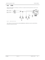
4.1. SIM Card
Decoupling capacitors must be added according to the drawings below as close as possible to the
SIM card connectors on UIM1_CLK, UIM1_RST, UIM1_VCC and UIM1_DATA signals to avoid EMC
issues and to comply with the requirements of ETSI and 3GPP standards covering the SIM electrical
interface.
A typical schematic including SIM detection is provided below.
Figure 1. EMC and ESD Components Close to the SIM
April 10, 2017

4119996 Rev 1.3 13
Hardware Integration Guide ESD Guidelines
4.2. USB
When the USB interface is externally accessible, it is required to have ESD protection on the USB_D+
and USB_D- signals.
Figure 2. ESD Protection for USB
Sierra Wireless recommends using a 90Ω DLP0NSN900HL2L EMC filter and an RCLAMP0503N or
ESD5V3U2U-03LRH ESD diode.
April 10, 2017

4119996 Rev 1.3 14
5. Legal Information
5.1. FCC Regulations
The HL8548 has been granted modular approval for mobile applications. Integrators may use the
HL8548 in their final products without additional FCC certification if they meet the following conditions.
Otherwise, additional FCC approvals must be obtained.
1. At least 20 cm separation distance between the antenna and the user’s body must be
maintained at all times.
2. To comply with FCC regulations limiting both maximum RF output power and human
exposure to RF radiation, the maximum antenna gain including cable loss in a mobile-only
exposure condition must not exceed:
3.0 dBi in the cellular band
5.0 dBi in the PCS band
3. The HL8548 may transmit simultaneously with other collocated radio transmitters within a
host device, provided the following conditions are met:
Each collocated radio transmitter has been certified by FCC for mobile application.
At least 20 cm separation distance between the antennas of the collocated transmitters
and the user’s body must be maintained at all times.
The output power and antenna gain must not exceed the limits and configurations
stipulated in the following table.
Device
Technology
Frequency
(MHz)
Maximum Antenna Gain (dBi)
EIRP Limits
(dBm)
Standalone
Collocated
HL8548
GPRS/EDGE 850
824-849
3
-
GPRS/EDGE 1900
1850-1910
5
5
-
UMTS 850
824-849
3
-
UMTS 1900
1850-1910
5
5
-
Collocated
transmitters
WLAN
2400-2500
-
-
27
5150-580
-
-
27
WiMAX
2300-2400
-
-
27
2500-2700
-
-
27
3300-3800
-
-
27
BT
2400-2500
-
-
20
3
3
April 10, 2017

4119996 Rev 1.3 15
Hardware Integration Guide Legal Information
4. The RF signal must be routed on the application board using tracks with a 50Ω characteristic
impedance. Basically, the characteristic impedance depends on the dielectric, the track width
and the ground plane spacing. In order to respect this constraint, Sierra Wireless
recommends using MicroStrip or StripLine structure and computing the Tracks width with a
simulation tool (like AppCad shown in the figure below and that is available free of charge at
http://www.agilent.com).
If a multi-layered PCB is used, the RF path on the board must not cross any signal (digital,
analog or supply).
5. A label must be affixed to the outside of the end product into which the HL8548 is
incorporated, with a statement similar to the following:
This device contains FCC ID: N7NHL8548
6. A user manual with the end product must clearly indicate the operating requirements and
conditions that must be observed to ensure compliance with current FCC RF exposure
guidelines.
The end product with an embedded HL8548 may also need to pass the FCC Part 15 unintentional
emission testing requirements and be properly authorized per FCC Part 15.
Note: If this accessory board is intended for use in a portable device, you are responsible for separate
approval to satisfy the SAR requirements of FCC Part 2.1093.
April 10, 2017

4119996 Rev 1.3 16
Hardware Integration Guide Legal Information
5.2. IC Regulations
This device complies with Industry Canada’s license-exempt RSSs. Operation is subject to the
following two conditions:
1. This device may not cause interference; and
2. This device must accept any interference, including interference that may cause undesired
operation of the device.
Le présent appareil est conforme aux CNR d’Industrie Canada applicables aux appareils radio
exempts de licence. L’exploitation est autorisée aux deux conditions suivantes:
1. l’appareil ne doit pas produire de brouillage;
2. l’utilisateur de l’appareil doit accepter tout brouillage radioélectrique subi, même si le
brouillage est susceptible d’en compromettre le fonctionnement.
5.2.1. Radiation Exposure Statement
This equipment complies with Canada radiation exposure limits set forth for an uncontrolled
environment.
This equipment should be installed and operated with minimum distance 20cm between the radiator
and your body.
Cet équipement est conforme Canada limites d'exposition aux radiations dans un environnement non
contrôlé.
Cet équipement doit être installé et utilisé à distance minimum de 20cm entre le radiateur et votre
corps.
This radio transmitter (IC: 2417C-HL8548) has been approved by Industry Canada to operate with the
antenna types listed below with the maximum permissible gain indicated. Antenna types not included
in this list, having a gain greater than the maximum gain indicated for that type, are strictly prohibited
for use with this device.
Le présent émetteur radio (IC: 2417C-HL8548) a été approuvé par Industrie Canada pour fonctionner
avec les types d'antenne énumérés ci dessous et ayant un gain admissible maximal. Les types
d'antenne non inclus dans cette liste, et dont le gain est supérieur au gain maximal indiqué, sont
strictement interdits pour l'exploitation de l'émetteur.
Table 4. Approved Antenna Types
Type
Gain
Connector
Dipole
2 dBi
R-SMA
April 10, 2017

4119996 Rev 1.3 17
6. References
6.1. Reference Documents
[1] AirPrime HL8548 and HL8548-G Product Technical Specification
Reference Number: 4114663
6.2. Terms and Abbreviations
Abbreviation
Definition
ADC
Analog to Digital Converter
AGC
Automatic Gain Control
AT
Attention (prefix for modem commands)
CDMA
Code Division Multiple Access
CF3
Common Flexible Form Factor
CLK
Clock
CODEC
Coder Decoder
CPU
Central Processing Unit
DAC
Digital to Analog Converter
DTR
Data Terminal Ready
EGNOS
European Geostationary Navigation Overlay Service
EMC
Electromagnetic Compatibility
EMI
Electromagnetic Interference
EN
Enable
ESD
Electrostatic Discharges
ETSI
European Telecommunications Standards Institute
FDMA
Frequency-division multiple access
GAGAN
GPS aided geo augmented navigation
GLONASS
Global Navigation Satellite System
GND
Ground
GNSS
Global Navigation Satellite System
GPIO
General Purpose Input Output
GPRS
General Packet Radio Service
GSM
Global System for Mobile communications
Hi Z
High impedance (Z)
IC
Integrated Circuit
IMEI
International Mobile Equipment Identification
I/O
Input / Output
LED
Light Emitting Diode
LNA
Low Noise Amplifier
MAX
Maximum
April 10, 2017

4119996 Rev 1.3 18
Hardware Integration Guide References
Abbreviation
Definition
MIN
Minimum
MSAS
Multi-functional Satellite Augmentation System
N/A
Not Applicable
PA
Power Amplifier
PC
Personal Computer
PCB
Printed Circuit Board
PCL
Power Control Level
PLL
Phase Lock Loop
PWM
Pulse Width Modulation
QZSS
Quasi-Zenith Satellite System
RF
Radio Frequency
RFI
Radio Frequency Interference
RMS
Root Mean Square
RST
Reset
RTC
Real Time Clock
RX
Receive
SCL
Serial Clock
SDA
Serial Data
SIM
Subscriber Identification Module
SMD
Surface Mounted Device/Design
SPI
Serial Peripheral Interface
SW
Software
PSRAM
Pseudo Static RAM
TBC
To Be Confirmed
TBD
To Be Defined
TP
Test Point
TX
Transmit
TYP
Typical
UART
Universal Asynchronous Receiver-Transmitter
UICC
Universal Integrated Circuit Card
USB
Universal Serial Bus
UIM
User Identity Module
VBATT
Main Supply Voltage from Battery or DC adapter
VSWR
Voltage Standing Wave Ratio
WAAS
Wide Area Augmentation System
April 10, 2017
-
 1
1
-
 2
2
-
 3
3
-
 4
4
-
 5
5
-
 6
6
-
 7
7
-
 8
8
-
 9
9
-
 10
10
-
 11
11
-
 12
12
-
 13
13
-
 14
14
-
 15
15
-
 16
16
-
 17
17
-
 18
18


Sierra Wireless N7NHL8548 Manuel utilisateur
- Taper
- Manuel utilisateur
- Ce manuel convient également à
dans d''autres langues
Autres documents
-
Maestro E206XT Manuel utilisateur
-
Continental FE4NA0210 Mode d'emploi
-
Eurotech ReliaGATE 20-25 Le manuel du propriétaire
-
Multitech MTQN-MNG1-B01.R1 Mode d'emploi
-
-
-
Eurotech ReliaGATE 10-12 Le manuel du propriétaire
-
-
-
Multitech MTQ-H5-B01 Mode d'emploi