Kichler Lighting 2019NI Manuel utilisateur
- Taper
- Manuel utilisateur

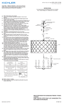
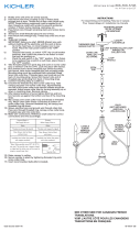
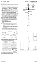
CAUTION – RISK OF SHOCK – Disconnect Power at the main circuit breaker panel or
main fuse box before starting and during the installation.
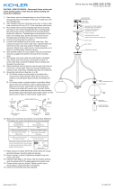
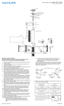
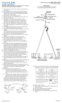
1) Passwirefromxturebodythroughcenterstem.
2) Screwcenterstemontothreadedpipeattopofxturebody.
3) Unscrewloopandtopstemslightlytohelpalignmentofupperarmassembly.
4) Attach upper arm to lower arm and ball at top of center stem using ball studs. If
hole in ball does not align with hole in upper arm rotate ball until holes align.
5) Tighten loop and top stem.
6) Turn off power.
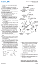
7) Take threaded pipe from parts bag and screw in screw collar loop a minimum of 6
mm (1/4”). Lock into place with hexnut.
8) Runanotherhexnutdownthreadedpipealmosttouchingrsthexnut.Nowscrew
threaded pipe into mounting strap. Mounting strap must be positioned with extrud
ed thread faced into outlet box. Threaded pipe must protrude out the back of
mounting strap. Connect mounting strap to outlet box.
9) Unscrewthethreadedringfromscrewcollarloop.Takecanopyandpassoverscrew
collarloop.Approximatelyonehalfofthescrewcollarloopexteriorthreadsshould
beexposed.Adjustscrewcollarloopbyturningassemblyupordowninmounting
strap.Removecanopy.
10) After desired position is found, tighten top hexnut up against the bottom of the mount-
ing strap.
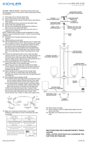
11)Slipcanopyoverscrewcollarloopandthreadonthreadedring.Attachchain(with
xtureconnected)tobottomofscrewcollarloop.Unscrewthreadedring,letcanopy
and threaded ring slip down.
12)Weaveelectricalwireandgroundwirethroughchainlinksnomorethan3inchesapart.
Passwirethroughthreadedring,canopy,screwcollarloop,threadedpipeandinto
outlet box.
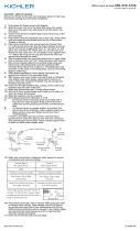
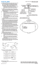
13) Grounding instructions: (See Illus. A or B).
A) Onxtureswheremountingstrapisprovidedwithaholeandtworaised
dimples. Wrap ground wire from outlet box around green ground screw, and
thread into hole.
B) Onxtureswhereacuppedwasherisprovided.Attachgroundwirefrom
outlet box under cupped washer and green ground screw, and thread into
mounting strap.
Ifxtureisprovidedwithgroundwire.Connectxturegroundwiretooutletboxgroundwire
withwireconnector(notprovided.)afterfollowingtheabovesteps.Neverconnectground
wiretoblackorwhitepowersupplywires.
14) Makewireconnections(connectorsnotprovided).Referencechartbelowforcorrect
connectionsandwireaccordingly.
15) Raise canopy to ceiling.
16) Secure canopy in place by tightening threaded ring onto screw collar loop.
17) Slip glass over socket at end of arm and allow to seat on socket cup.
AVERTISSEMENT – RISQUES D’ÉLECTROCUTION – COUPER LE COURANT
AU PANNEAU DE DISJONCTION PRINCIPAL OU À LA BOÎTE À FUSIBLES
PRINCIPALE AVANT DE COMMENCER ET LE MAINTENIR COUPÉ DURANT
L’INSTALLATION.
1) Passerlelduluminaireàtraverslatigecentrale.
2) Visserlatigecentralesurletubeletéau-dessusduluminaire.
3) Dévisserlaboucleetlatigedudessuspourfaciliterl’alignementdubras
supérieur.
4) Raccorderlebrassupérieuraubrasinférieuretàlaboulesurledessusdelatige
centraleàl’aidedespivotsàrotule.Siletroudanslaboulen’estpasalignéavecle
troudanslebrassupérieur,tournezlaboulejusqu’àcequ’ellesoitalignée.
5) Serrerlabouleetlatigesupérieure.
6) Couper l’alimentation.
7) Retirerletubeletédusacdepiècesetlevisserdansl’anneauducollieràvissurau
moins6mm(1/4”).Verrouillerenplaceavecl’écrouhexagonal.
8) Visserunautreécrouhexagonalsurletubeletéjusqu’àcequ’iltouchepresqueau
premierécrouhexagonal.Vissermaintenantletubeletédansl’étrierdemontage.
L’étrierdemontagedoitêtrepositionnéaveclesletsextrudésverslaboîteàprises.
Letubeletédoitêtreensailliesurl’arrièredel’étrierdemontage.Connecterl’étrier
demontageàlaboîteàprises.
9) Dévisserlabagueletéedel’anneauducollieràvis.Prendrelecouvercleetlepasser
par-dessusl’anneauducollieràvis.Environlamoitiédesletsextérieursdel’anneau
ducollieràvisdevraientêtreexposés.Ajusterl’anneauducollieràvisentournant
l’anneauducollieràvisverslehautoulebasdansl’étrierdemontage.Enleverle
couvercle.
10) Aprèsavoirtrouvélapositiondésirée,serrerl’écrouhexagonalsupérieurcontrele
dessousdel’étrierdemontage.
11) Glisserlecouverclepar-dessusl’anneauducollieràvisetvissersurletubeleté.
Raccorderlachaîne(avecleluminaireconnecté)audessousdel’anneauducollierà
vis.Dévisserlabagueletée,laisserglisserverslebaslecouvercleetlabagueletée.
12) Passerlelélectriqueetleldemiseàlaterreàtraverslesmaillonsdelachaîneau
moinsàtousles3pouces.Passerlelàtraverslabagueletée,lecouvercle,
l’anneauducollieràvis,letubeleté,jusquedanslaboîteàprises.
13) Directivesdemiseàlaterre:(ConsulterIllus.AouB).
A) Pourlesluminairesdontl’étrierdemontagefournicomporteuntrouetdeux
cranssoulevés:enroulerleldemiseàlaterreprovenantdelaboîteàprises
autourdelavisdeterreverte,etlavisserdansletrou.
B) Pourlesluminairesquicomportentunoeilletcuivré:placerleldemiseàla
terreprovenantdelaboîteàprisessousl’oeilletcuivréetlavisdeterreverteet
GREEN GROUND
SCREW
CUPPED
WASHER
OUTLET BOX
GROUND
FIXTURE
GROUND
DIMPLES
WIRE CONNECTOR
OUTLET BOX
GROUND
GREEN GROUND
SCREW
FIXTURE
GROUND
A
B
Connect Black or
Red Supply Wire to:
Connect
White Supply Wire to:
Black White
*Parallel cord (round & smooth) *Parallel cord (square & ridged)
Clear, Brown, Gold or Black
without tracer
Clear, Brown, Gold or Black
with tracer
Insulated wire (other than green)
with copper conductor
Insulated wire (other than green)
with silver conductor
*Note: When parallel wires (SPT I & SPT II)
are used. The neutral wire is square shaped
or ridged and the other wire will be round in
shape or smooth (see illus.)
Neutral Wire
Date Issued: 9/12/16
IS-2019-CB
BALL STUD
À ROTULE
BOTTOM ARM
BRASINFÉRIEURE
SOCKET
DOUILLE
THREADED PIPE
TUBEFILTÉ
visserlavisdansletroudel’étrierdemontage.
Sileluminairecomporteunldemiseàlaterre:Connecterleldemiseàlaterre
duluminaireauldemiseàlaterredelaboîteàprisesavecunconnecteurdel(non
fourni)aprèsavoircomplétélesétapesplushaut.Nejamaisconnecterunldemiseà
laterreàunld’alimentationélectriquenoiroublanc.
14) Fairelesconnexionsdel(connecteursnonfournis).Vousréférerautableauplus
baspourdesconnexionscorrectesetuncâblageapproprié.
15) Souleverlecouverclejusqu’auplafond.
16) Immobiliserlecouvercleenplaceenserrantletubeletésurl’anneauducollierà
vis.
17) Glisserleverrepar-dessusladouilleàl’extrémitédubrasetlaisserlereposersur
la coupelle de la douille.
SOCKETRING
ANNEAUDEDOUILLE
FIXTUREBODY
CORPSDULUMINAIRE
ARANDELA
CONCAVA
TIERRA DE LA
CAJA DE SALIDA
TORNILLO DE TIERRA,
VERDE
DEPRESIONES
TIERRA
ARTEFACTO
CONECTOR DE ALAMBRE
TIERRA DE LA
CAJA DE SALIDA
TORNILLO DE TIERRA,
VERDE
TIERRA
ARTEFACTO
A
B
Conectar el alambre de
suministro negro o rojo al
Conectar el alambre de
suministro blanco al
Negro Blanco
*Cordon paralelo (redondo y liso)
*Cordon paralelo (cuadrado y estriado)
Claro, marrón, amarillio o negro
sin hebra identificadora
Claro, marrón, amarillio o negro
con hebra identificadora
Alambre aislado (diferente del verde)
con conductor de cobre
Alambre aislado (diferente del
verde) con conductor de plata
*Nota: Cuando se utiliza alambre paralelo
(SPT I y SPT II). El alambre neutro es de forma
cuadrada o estriada y el otro alambre será de
forma redonda o lisa. (Vea la ilustracíón).
Hilo Neutral
MOUNTINGSTRAP
ÉTRIERDEMONTAGE
HEXNUT
ÉCROUHEXAGONAL
THREADED PIPE
TUBEFILTÉ
CANOPY
COUVERCLE
THREADEDRING
BAGUEFILETÉE
GLASS
VERRE
LOOP
BOUCLE
CENTERSTEM
TIGECENTRALE
UPPER ARM
BRASSUPÉRIEURE
DU CORPS
We’re here to help 866-558-5706
Hrs: M-F 9am to 5pm EST
-
 1
1
Kichler Lighting 2019NI Manuel utilisateur
- Taper
- Manuel utilisateur
dans d''autres langues
- English: Kichler Lighting 2019NI User manual
Documents connexes
-
 Kichler Lighting 43827ANW Manuel utilisateur
-
 Kichler Lighting 43234OZ Manuel utilisateur
-
 Kichler Lighting 1897NI Manuel utilisateur
-
 Kichler Lighting 42894CH Manuel utilisateur
-
 Kichler Lighting 44064NI Manuel utilisateur
-
 Kichler Lighting 43895OZ Manuel utilisateur
-
 Kichler Lighting 43871OZ Manuel utilisateur
-
 Kichler Lighting 2347NI Manuel utilisateur
-
 Kichler Lighting 43721PN Manuel utilisateur
-
 Kichler Lighting 43999CH Manuel utilisateur


