Drive Medical RTL10275 Manuel utilisateur
- Taper
- Manuel utilisateur

exercise peddler
with digital display
ejercitador de pedales
con pantalla digital
pédalier exerciseur
avec afficheur
item # RTL10275
www.drivemedical.com
EU Authorized Representative
Drive Medical LTD
Ainley’s Industrial Estate
Elland, West Yorkshire,
United Kingdom HX5 9JP
www.drivemedical.com
Rev.1.08.26.14

Rev.1.08.26.14
assembly instructions folding
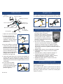
1. Remove contents from box.
2. Pull legs in opposite
direction until locking but-
ton “snaps” into locking
receiver (See figure A).
5. The pedal straps have
2 sets of holes to allow you
to adjust the length of the
strap around your foot or
shoe. (See figure C)
automatic operation
battery replacement
If the display does not come on or reads incorrectly, the battery
requires replacement.
To replace the battery, use a small screw driver and remove
the display panel. Turn the display panel over and remove
the watch- style battery. Insert a new battery and replace the
display panel.
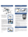
Footrest
pad
Swivel sha
Tension knob
Footrest plate
Connecting
Tube
Hinge
Plastic
cover
Digital Display
Tube
Pad
figure A
4. Insert tension knob on top of peddler and turn
clockwise to tighten. The tension knob will increase/
decrease the amount of tension on the peddler.
Tighten/ loosen to a level that feels comfortable.
3. Attach digital display to the
peddler by sliding the loop
over the tension knob recep-
tacle located on the top of
the peddler. Push down gently
on the display so the clasp on
the back of the display attach-
es to the peddler frame. (See
figure B)
1. MODE (Red Button): This control
allows you to select a particular
function. To start, press and hold
the Red Button for 4 seconds. The
LED will display the different func-
tions. (After a few minutes without
any movememnt, the unit will
automatically shut off).
2. To select a function, wait until the
4 second set up is complete. Push
the Red Button and the arrow will move through the func-
tions. When the desired function is selected, simply use the
peddler and the unit will calculate the exercise.
3. TIME: Determines the amount of time the peddler has been
operating.
4. COUNTER (CNT): Determines the amount of steps while
operating the peddler.
5. CALORIE (CAL): Determines the amount of calories burned
while using the peddler.
6. REPS PER MINUTE (R.P.M.) Automatically calculates the
repetitions per minute.
7. SCAN: Will automatically review the results of all functions.
Operating Guide
Parts
Step 1
This product is already
pre-assembled with
only the tension
adjustment bolt packed
separately to reduce
the overall carton size.
Assembly Guide
The spring release
buttons can be pressed
in to allow the lower leg
sections to be re-folded
under the central
housing.
Step 4
The pedal straps have 2
sets of holes to allow
you to adjust the length
of the strap around your
foot or shoe.
Finished Assembly
When assembled your
pedal exerciser should
look like this.
After removing all the
plastic wrapping insert
the tension adjustment
bolt into the top of the
central housing and
lightly tighten.
Step 3
Unfold each of the
lower leg sections and
ensure the spring
release buttons are
engaged / clicked into
place.
Heat from friction
Parts of this pedal
exerciser, including the
pedal shaft near the
central housing, may
become warm or hot
during use.
Counter 3
The multi-function
counter will stop
"counting" if you stop
turning the pedals.
After a few minutes
without any movement
it will turn itself off.
Care when folding
Safety Warnings
Counter 1
Press the MODE /
RESET button on the
multi-function counter to
turn it on. Press it
again to select the
TIME, CAL and RPM
displays.
Counter 2
The SCAN option will
cycle through the TIME,
CAL and RPM displays
with each one being
displayed on the screen
for a few seconds.
Take care when folding
the pedal exerciser and
keep fingers, feet and
legs clear of the folding
mechanism or frame.
Limited use design
This pedal exerciser is
designed for limited or
domestic usage and is
not designed for high or
commercial usage.
Step 2
figure B
To fold, depress push pin and fold leg inward. Repeat
for second leg. (see figure D)
figure D
figure C

instrucciones/ manual de operación
operación automática
como cambiar la batería
Si la pantalla no se enciende o si las lecturas son incorrectas
necesita cambiar las baterías.
Para cambiar la batería, utilice un desarmador pequeño y quite
el panel de la pantalla. Gire el panel de la batería y quite la
batería tipo reloj. Instale una batería nueva y vuelva a colocar
el panel de la pantalla en su lugar.
Almohadilla para
apoyar los pies
Eje giratorio
Perilla en forma de cruz
Placa para
apoyar los pies
Tubo conector
Uniones
activas
Cubierta
de plástico
Pantalla digital
Tubo
Cubierta
del tubo
1. MODE (Botón rojo): Este control le
permite seleccionar una función
en particular. Para iniciar, pre-
sione y mantenga presionado el
Botón Rojo por 4 segundos. La pantalla
LED mostrará las diferentes funciones.
(Si después de encender la unidad no se
realiza ninguna actividad, la unidad se
apagará automáticamente).
2. Para seleccionar una función, espere hasta que pasen los 4
segundos de configuración. Presione el Botón Rojo y la flecha
se desplazará a lo largo de las funciones. Cuando seleccione
la función deseada, simplemente utilice su ejercitador de
pedal y la unidad calculará el ejercicio que realiza.
3. TIEMPO: Determina el tiempo que se ha estado utilizando el
ejercitador de pedal.
4. MOSTRADOR (CNT): Determina la cantidad de pasos al
momento de estar operando el ejercitador de pedal.
5. CALORÍAS (CAL): Determina la cantidad de calorías quema
das al momento de estar operando el ejercitador de pedal.
6. RÉPÉTITIONS PAR MINUTE (R.P.M): Calcula
automáticamente las repeticiones por minuto.
7. SCAN: Evaluará automáticamente los resultados de todas
las funciones.
Operating Guide
Parts
Step 1
This product is already
pre-assembled with
only the tension
adjustment bolt packed
separately to reduce
the overall carton size.
Assembly Guide
The spring release
buttons can be pressed
in to allow the lower leg
sections to be re-folded
under the central
housing.
Step 4
The pedal straps have 2
sets of holes to allow
you to adjust the length
of the strap around your
foot or shoe.
Finished Assembly
When assembled your
pedal exerciser should
look like this.
After removing all the
plastic wrapping insert
the tension adjustment
bolt into the top of the
central housing and
lightly tighten.
Step 3
Unfold each of the
lower leg sections and
ensure the spring
release buttons are
engaged / clicked into
place.
Heat from friction
Parts of this pedal
exerciser, including the
pedal shaft near the
central housing, may
become warm or hot
during use.
Counter 3
The multi-function
counter will stop
"counting" if you stop
turning the pedals.
After a few minutes
without any movement
it will turn itself off.
Care when folding
Safety Warnings
Counter 1
Press the MODE /
RESET button on the
multi-function counter to
turn it on. Press it
again to select the
TIME, CAL and RPM
displays.
Counter 2
The SCAN option will
cycle through the TIME,
CAL and RPM displays
with each one being
displayed on the screen
for a few seconds.
Take care when folding
the pedal exerciser and
keep fingers, feet and
legs clear of the folding
mechanism or frame.
Limited use design
This pedal exerciser is
designed for limited or
domestic usage and is
not designed for high or
commercial usage.
Step 2
Rev.1.08.26.14
1. Saque las partes de la caja.
2. Jale las patas en la dirección
opuesta hasta que el botón de
bloqueo “se encaje” dentro del
receptor de bloqueo (vea la
figura A).
5. Las correas del pedal tiene 2
juegos de orificios que per-
miten ajustar la longitud de la
correa alrededor de su pie o
zapato. (Vea la figura C)
figura A
4. Introduzca la perilla de tensión sobre el ejercitador de
pedal y gire en sentido de las manecillas del reloj para
apretar. La perilla de tensión aumentará/ disminuirá la
cantidad de tensión sobre el ejercitador de pedal.
Apriete/ afloje la perilla al nivel en donde se sienta
cómodo.
3. Fije la pantalla digital al
dispositivo de pedales al deslizar
el aro sobre el receptáculo de
la perilla de tensión ubicado en
la parte superior del aparato
con pedales. Empuje levemente
sobre la pantalla para que el
broche en la parte trasera de la
pantalla se sujete al armazón del
aparato con pedales (vea la figura B).
figura B
figura C
para doblarlo
Para doblarlo, presione la clavija de presión y doble la pata
hacia adentro. Repita los mismos pasos para la segunda
pata. (vea la figura D)
figura D

instructions
utilisation en mode automatique
remplacement de la pile
Si l’afficheur ne fonctionne pas ou affiche incorrectement, vous
devez remplacer la pile.
Pour remplacer la pile, utilisez un petit tournevis et retirez le
panneau d’affichage. Faites basculer le panneau et retirez la
pile de type « pièce de monnaie ». Insérez une nouvelle pile et
replacez le panneau.
Appui du
repose-pied
Axe de rotation
Bouton croisillon
Plateau du
Repose-pied
Tube de
raccordement
Joints actifs
Protecteur
Affichage numérique
Tube
Protège-tube
1. MODO (bouton rouge) : Ce bouton
permet de choisir une fonction
particulière. Pour démarrer, appuyez sur
le bouton rouge et maintenez-le enfoncé
pendant quatre secondes. L’afficheur
ACL affichera les différentes fonctions
(l’afficheur s’éteint automatiquement s’il
n’y a aucune activité).
2. Pour choisir une fonction, attendez que
la mise en route de quatre secondes soit complétée
Appuyez sur le bouton rouge pour déplacer la flèche
d’une fonction à l’autre. Lorsque la fonction désirée est
sélectionnée, commencez à pédaler et l’afficheur indiquera
votre progrès.
3. DURÉE (TIME): Indique la durée d’utilisation du pédalier.
4. COMPTEUR (CNT) : Indique le nombre de rotations
du pédalier.
5. CALORIES (CAL) : Indique la dépense d’énergie, en
calories, découlant de l’utilisation du pédalier.
6. CADENCE (Rotations par minutes – RPM) : Indique le
nombre de rotations du pédalier, par minute.
7. SÉQUENCE (SCAN): Passe en séquence toutes les
fonctions de l’afficheur.
Operating Guide
Parts
Step 1
This product is already
pre-assembled with
only the tension
adjustment bolt packed
separately to reduce
the overall carton size.
Assembly Guide
The spring release
buttons can be pressed
in to allow the lower leg
sections to be re-folded
under the central
housing.
Step 4
The pedal straps have 2
sets of holes to allow
you to adjust the length
of the strap around your
foot or shoe.
Finished Assembly
When assembled your
pedal exerciser should
look like this.
After removing all the
plastic wrapping insert
the tension adjustment
bolt into the top of the
central housing and
lightly tighten.
Step 3
Unfold each of the
lower leg sections and
ensure the spring
release buttons are
engaged / clicked into
place.
Heat from friction
Parts of this pedal
exerciser, including the
pedal shaft near the
central housing, may
become warm or hot
during use.
Counter 3
The multi-function
counter will stop
"counting" if you stop
turning the pedals.
After a few minutes
without any movement
it will turn itself off.
Care when folding
Safety Warnings
Counter 1
Press the MODE /
RESET button on the
multi-function counter to
turn it on. Press it
again to select the
TIME, CAL and RPM
displays.
Counter 2
The SCAN option will
cycle through the TIME,
CAL and RPM displays
with each one being
displayed on the screen
for a few seconds.
Take care when folding
the pedal exerciser and
keep fingers, feet and
legs clear of the folding
mechanism or frame.
Limited use design
This pedal exerciser is
designed for limited or
domestic usage and is
not designed for high or
commercial usage.
Step 2
Rev.1.08.26.14
1. Retirez le contenu de la boîte.
2. Tirez les pieds dans des
directions opposées jusqu’à
ce que les boutons de ver-
rouillages « cliquent » dans les
orifices de verrouillage (voir
illustration A).
5. La courroie de la pédale
comporte deux séries de
trous qui permettent d’ajuster
la courroie autour de votre
pied (voir figure C).
figure A
4. Insérez le bouton de tension sur le dessus du pédalier et
tournez dans le sens horaire pour serrer. Ce bouton
augmente / diminue la tension du pédalier. Serrez ou
desserrez le bouton de manière à régler l’effort à un niveau
confortable.
3. Pour fixer l’afficheur numérique
à l’exerciseur, glissez la boucle
par-dessus le bouton de réglage
de la tension situé sur le dessus
de l’exerciseur. Appuyez délicate-
ment sur l’afficheur pour que
l’attache à l’arrière de l’afficheur
s’engage dans le cadre de
l’exerciseur (voir figure B).
figure B
figure C
rangement
Pour replier, enfoncez le bouton à ressort et repliez le pied
vers l’intérieur. Répétez pour le second pied (voir figure D).
figure D

lifetime limited
warranty
© 2014 Medical Depot, Inc. All rights reserved.
Drive is a trademark of Medical Depot, Inc.
Port Washington N.Y. 11050 USA Made in China
garantía limitada
de por vida
Su producto marca Drive está garantizado de por
vida del producto por el comprador-consumidor
original de no tener defectos en los materiales y la
fabricación.
Este aparato fue construido de acuerdo a estándares
rigurosos y cuidadosamente inspeccionado previo a
su envío. Esta Garantía Limitada de por Vida es una
expresión de nuestra confianza en los materiales y la
fabricación de nuestros productos y nuestra seguri-
dad para el consumidor dada por años de servicios
confiables.
Esta garantía no cubre fallas del aparato debidas
a mal uso o negligencia por parte del propietario o
por el uso y desgaste normales. Esta garantía no se
extiende a los componentes no durables, tales como
los accesorios de goma, rueditas y mangos que están
sujetos a desgaste normal y necesitan reemplazo
periódico.
Si usted tiene preguntas acerca de su aparato
Drive o esta garantía, por favor contacte a un
representante autorizado de Drive.
©2014 Medical Depot, Inc. Todos los derechos reservados.
Drive es marca registrada de medical depot, Inc.
Port Washington NY 11050 USA Hecho en China
Your Drive branded product is warrantied to be
free of defects in materials and workmanship for
the lifetime of the product for the original con-
sumer purchaser.
This device was built to exacting standards and
carefully inspected prior to shipment. This Lifetime
Limited Warranty is an expression of our confi-
dence in the materials and workmanship of our
products and our assurance to the consumer of
years of dependable service.
This warranty does not cover device failure
due to owner misuse or negligence, or normal
wear and tear. The warranty does not extend to
non-durable components, such as rubber
accessories, casters, and grips, which are subject
to normal wear and need periodic replacement.
If you have a question about your Drive device or
this warranty, please contact an authorized Drive
dealer.
Rev.1.08.26.14

garantie à vie,
limitée
Ce produit Drive est garanti exempt de tout défaut
de matériau, de fabrication ou de main d’oeuvrepour
la vie du product pour l’acheteur de consommateur
original.
Cet appareil a été fabriqué selon des normes
de qualité rigoureuses et inspecté avant de qui
ter l’usine. Cette garantie à vie limitée, est un
témoignage de la confiance que nous portons
aux matériaux, à la main d’oeuvre, ainsi qu’ aux
procédés de fabrication requis pour produire
nos appareils afin qu’ils puissent vous assis-
ter de manière fiable et sécuritaire pendant de
nombreuses années.
Cette garantie ne peut être invoquée dans les cas
d’usage inapproprié de l’appareil, en cas de négli-
gence ou d’usure normale. Cette garantie ne couvre
pas les pièces qui, de par leur nature, ont une durée
de vie plus courte, tel que les embouts de caoutchouc,
poignées de mousse, roues et pneus, qui doivent être
périodiquement remplacés.
Pour toute question sur cet appareil ou sur sa garan-
tie, veuillez svp, contacter votre détaillant autorisé
de produits Drive.
© 2014 Medical Depot, Inc. Tous droits réservés.
Drive est une marque de commerce de Medical Depot, Inc.
Port Washington, NY 11050 USA Fabriqué en Chine
www.drivemedical.com
Rev.1.08.26.14
-
 1
1
-
 2
2
-
 3
3
-
 4
4
-
 5
5
-
 6
6


Drive Medical RTL10275 Manuel utilisateur
- Taper
- Manuel utilisateur
dans d''autres langues
- English: Drive Medical RTL10275 User manual
- español: Drive Medical RTL10275 Manual de usuario