
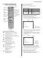
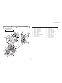
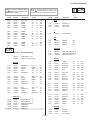
COLOR REAR VIDEO PROJECTOR
SERVICE MANUAL
RA-6
CHASSIS
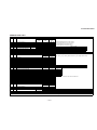
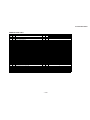
MODEL NAME REMOTE COMMANDER DESTINATION CHASSIS NO.
KP-51WS500
RM-Y909 US/CND SCC-P65HA
KP-57WS500
RM-Y909 US/CND SCC-P65JA
KP-65WS500
RM-Y909 US/CND SCC-P65KA
9-965-932-01
ORIGINAL MANUAL ISSUE DATE: 7/2002
ALL REVISIONS AND UPDATES TO THE ORIGINAL MANUAL ARE APPENDED TO THE END OF THE PDF FILE.
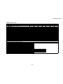
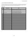
REVISION DATE REVISION TYPE SUBJECT
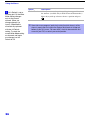
7/2002 No revisions or updates are applicable at this time.
HISTORY INFORMATION FOR THE FOLLOWING MANUAL:

COLOR REAR VIDEO PROJECTOR
SERVICE MANUAL
RA-6
CHASSIS
MODEL NAME REMOTE COMMANDER DESTINATION CHASSIS NO.
KP-51WS500
RM-Y909 US/CND SCC-P65HA
KP-57WS500
RM-Y909 US/CND SCC-P65JA
KP-65WS500
RM-Y909 US/CND SCC-P65KA
9-965-932-01
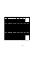
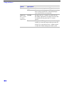
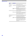
Self Diagnosis
Supported model
KP-65WS500 RM-Y909

— 3 —
KP-51WS500/57WS500/65WS500
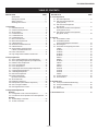
TABLE OF CONTENTS
SpeciÞ cations ...................................................................... 4
Warnings and Cautions ....................................................... 5
Safety Check-Out ................................................................ 6
Self-Diagnostic Function...................................................... 7
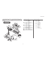
1. Disassembly
1-1. Rear Board Removal ........................................................... 10
1-2. Chassis Assembly Removal ................................................ 10
1-3. Service Position................................................................... 10
1-4. H2 Board Removal .............................................................. 11
1-5. H1 Board Removal .............................................................. 11
1-6. H3 Board Removal .............................................................. 11
1-7. Mirror Cover Removal ......................................................... 12
1-8. Beznet Assembly Removal.................................................. 12
1-9. S Board Removal ................................................................ 12
1-10. AD Board and B Board Removal......................................... 12
1-11. G Board Removal ................................................................ 13
1-12. Terminal Board, A Board, D Board,
U Board, and UD Board Removal ....................................... 13
1-13. Picture Tube Removal ......................................................... 14
1-14. High-Voltage Cable Installation and Removal ..................... 14
2. Set-up Adjustments
2-1. Screen Voltage Adjustment (Coarse Adjustment)................ 15
2-2. Screen (G2) Voltage Adjustment (Fine Adjustment) ............ 15
2-3. Deß ection Yoke Tilt Adjustment ........................................... 15
2-4. Focus Lens Adjustment ....................................................... 16
2-5. Focus VR Adjustment .......................................................... 16
2-6. 2-Pole Magnet and Centering Magnet Adjustment.............. 17
2-7. Centering Magnet Adjustment ............................................. 17
2-8. 4-Pole Magnet Adjustment .................................................. 17
2-9. Blue Defocus Adjustment .................................................... 17
2-10. Electrical Adjustments
By Remote Commander ...................................................... 18
2-11. Service Data Lists................................................................ 19
2-12. Registration Adjustment....................................................... 38
2-13. PJE Adjustment (Sub Deß ection Adjustment)...................... 40
2-14. Auto Convergence Offsets .................................................. 42
2-15. Auto Registration Error Codes............................................. 43
3. Safety Related Adjustments
(D Board)
3-1. HV Regulation Circuit Check and Adjustment ..................... 45
3-2. HV Hold Down Circuit Operation Check and Adjustment .... 45
(G Board)
3-3. +B Max Voltage ConÞ rmation.............................................. 46
3-4. +B OVP ConÞ rmation .......................................................... 46
4. Circuit Adjustments
4-1. Blue Offset Adjustment ........................................................ 47
4-2. P&P Sub Contrast Adjustment
(Video) (SCON) ................................................................... 47
4-3. P&P Sub Contrast Adjustment
(RF) (SCON)........................................................................ 47
4-4. P&P Sub-Hue and Sub-Color Adjustment
(Video) (SHUE, SCOL)........................................................ 47
4-5. P&P Sub-Hue and Sub-Color Adjustment
(RF) (SHUE, SCOL) ............................................................ 48
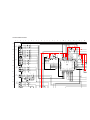
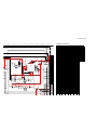
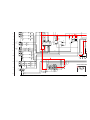
5. Diagrams
5-1. Circuit Boards Location ....................................................... 49
5-2. Printed Wiring Boards
and Schematic Diagrams Information ................................. 49
5-3. Block Diagrams ................................................................... 51
5-4. Schematics and Supporting Information.............................. 54
V Board................................................................................ 54
CR Board............................................................................. 55
CG Board............................................................................. 56
CB Board ............................................................................. 57
UD Board............................................................................. 58
D Board ............................................................................... 60
B Board................................................................................ 63
AD Board ............................................................................. 66
A Board................................................................................ 67
U Board ............................................................................... 74
G Board ............................................................................... 76
H2 Board ............................................................................. 77
H1 Board ............................................................................. 78
H3 Board ............................................................................. 79
S Board................................................................................ 79
5-5. IC Block Diagrams............................................................... 80
5-6. Semiconductors................................................................... 84
6. Exploded Views
6-1. Cover (KP-51WS500/57WS500 Only)................................. 85
6-2. Cover (KP-65WS500 Only) ................................................. 86
6-3. Chassis................................................................................ 87
6-4. Picture Tube ....................................................................... 88
7. Electrical Parts List ........................................................................ 89
SECTION TITLE PAGE SECTION TITLE PAGE

— 4 —
KP-51WS500/57WS500/65WS500
120V AC, 60Hz
230W
Under 1 W
DVI-HDTV
1 terminal, 3.3V T.M.D.S., 50 ohms
The DVI-HDTV input terminal is compliant with the EIA-861
standard and is not intended for use with personal computers.
Video (IN)
4 total (1 on front panel)
1Vp-p, 75ohms unbalanced, sync negative
S Video (IN)
3 total (1 on front panel)
Y: 1Vp-p, 75ohms unbalanced, sync negative
C: 0.286Vp-p (Burst signal), 75ohms
Audio (IN)
6 total (1 on front panel)
500 mVrms (100% modulation)
Impedance:47 kilo ohms
Projection System
3 picture tubes, 3 lenses, horizontal in-line system
Picture Tube
7-inch high-brightness monochrome tubes (6.3 raster size),
with optical coupling and liquid cooling system.
Projection Lenses
High performance, large diameter hybrid lens F1.1
Antenna
75 ohm external terminal for VHF/UHF
Television System
NTSC, American TV Standard
Channel Coverage
VHF: 2-13/ VHF: 14-69/ CATV: 1-125
SPECIFICATIONS
Design and specifi cations are subject to change without notice.
Power Requirements
Power Consumption (W)
In Use (Max)
In Standby
Inputs/Outputs
Screen Size (measured diagonally)
51 inches (KP-51WS500)
57 inches (KP-57WS500)
65 inches (KP-65WS500)
Supplied Accessories
Remote Control RM-Y909
Batteries (2) size AA (R6)
Optional Accessories
A/V Cable (VMC-810/820/830 HG)
Audio Cable (RKC-515HG)
Component Video Cable (VMC-10/30 HG)
Control S Cable (RK-G69HG)
AV Receiver (STR-V555ES or equivalent)
Audio (VAR/RIX)
1 total
500 mVrms at the maximum volume setting (Variable)
500 mVrms (Fixed)
Impedance (Output):1 kilo ohm
TV Out
1 total
Video: 1 Vp-p 75 ohms unbalanced, Sync negative
Audio: 500 m Vrms (100% modulation)
Impedance (output): 1 kilo ohms
Control S (IN/OUT)
1 total
Minijacks
Component Video Input
2 (Y, P
B
, P
R
)
Y: 1.0 Vp-p, 75 ohms unbalanced, sync negative
P
B
: 0.7 Vp-p, 75 ohms;
P
R
: 0.7 Vp-p, 75 ohms
RF Inputs
2 total
Converter
1 total
KP-51WS500 KP-57WS500
KP-65WS500
20W x 2
1194 x 1310 x 630 mm 1326 x 1377 x 690 mm 1542 x 1452 x 735 mm
47
1/8
x 51
5/8
x 24
7/8
in 52
1/4
x 54
1/4
x 27
1/4
in 61 x 57 x 29 in
76 kg 89 kg 125 kg
167 lbs 9 oz 196 lbs 3 oz 275 lbs 8 oz
Speaker Output (W)
Dimensions (W x H x D)
mm
in
Mass kg
lbs

— 5 —
KP-51WS500/57WS500/65WS500
WARNINGS AND CAUTIONS
CAUTION
Short circuit the anode of the picture tube and the anode cap to the metal chassis, CRT shield, or carbon painted on the CRT,
after removing the anode.
WARNING!!
An isolation transformer should be used during any service to avoid possible shock hazard, because of live chassis. The chassis of
this receiver is directly connected to the ac power line.
! SAFETY-RELATED COMPONENT WARNING!!
Components identifi ed by shading and
!
mark on the schematic diagrams, exploded views, and in the parts list are critical for
safe operation. Replace these components with Sony parts whose part numbers appear as shown in this manual or in supplements
published by Sony. Circuit adjustments that are critical for safe operation are identifi ed in this manual. Follow these procedures
whenever critical components are replaced or improper operation is suspected.
ATTENTION!!
Apres avoir deconnecte le cap de l’anode, court-circuiter l’anode du tube cathodique et celui de l’anode du cap au chassis metallique
de l’appareil, ou la couche de carbone peinte sur le tube cathodique ou au blindage du tube cathodique.
Afi n d’eviter tout risque d’electrocution provenant d’un chássis sous tension, un transformateur d’isolement doit etre utilisé lors de tout
dépannage. Le chássis de ce récepteur est directement raccordé à l’alimentation du secteur.
! ATTENTION AUX COMPOSANTS RELATIFS A LA SECURITE!!
Les composants identifi es par une trame et par une marque
!
sur les schemas de principe, les vues explosees et les listes de
pieces sont d’une importance critique pour la securite du fonctionnement. Ne les remplacer que par des composants Sony dont
le numero de piece est indique dans le present manuel ou dans des supplements publies par Sony. Les reglages de circuit dont
l’importance est critique pour la securite du fonctionnement sont identifi es dans le present manuel. Suivre ces procedures lors de
chaque remplacement de composants critiques, ou lorsqu’un mauvais fonctionnement suspecte.

— 6 —
KP-51WS500/57WS500/65WS500
SAFETY CHECK-OUT
After correcting the original service problem, perform the following
safety checks before releasing the set to the customer:
1. Check the area of your repair for unsoldered or poorly soldered
connections. Check the entire board surface for solder splashes and
bridges.
2. Check the interboard wiring to ensure that no wires are “pinched” or
touching high-wattage resistors.
3. Check that all control knobs, shields, covers, ground straps, and
mounting hardware have been replaced. Be absolutely certain that
you have replaced all the insulators.
4. Look for unauthorized replacement parts, particularly transistors,
that were installed during a previous repair. Point them out to the
customer and recommend their replacement.
5. Look for parts which, though functioning, show obvious signs of
deterioration. Point them out to the customer and recommend their
replacement.
6. Check the line cords for cracks and abrasion. Recommend the
replacement of any such line cord to the customer.
7. Check the B+ and HV to see if they are specifi ed values. Make sure
your instruments are accurate; be suspicious of your HV meter if sets
always have low HV.
8. Check the antenna terminals, metal trim, “metallized” knobs, screws,
and all other exposed metal parts for AC leakage. Check leakage
as described below.
Leakage Test
The AC leakage from any exposed metal part to earth ground and from
all exposed metal parts to any exposed metal part having a return to
chassis, must not exceed 0.5 mA (500 microamperes). Leakage current
can be measured by any one of three methods.
1. A commercial leakage tester, such as the Simpson 229 or
RCA WT-540A. Follow the manufacturers’ instructions to use these
instructions.
2. A battery-operated AC milliammeter. The Data Precision 245 digital
multimeter is suitable for this job.
3. Measuring the voltage drop across a resistor by means of a VOM
or battery-operated AC voltmeter. The “limit” indication is 0.75 V,
so analog meters must have an accurate low voltage scale. The
Simpson’s 250 and Sanwa SH-63TRD are examples of passive
VOMs that are suitable. Nearly all battery-operated digital multimeters
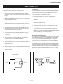
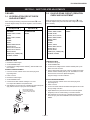
that have a 2 VAC range are suitable (see Figure A).
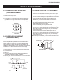
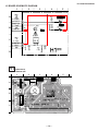
How to Find a Good Earth Ground
A cold-water pipe is a guaranteed earth ground; the cover-plate retaining
screw on most AC outlet boxes is also at earth ground. If the retaining
screw is to be used as your earth ground, verify that it is at ground
by measuring the resistance between it and a cold-water pipe with an
ohmmeter. The reading should be zero ohms.
If a cold-water pipe is not accessible, connect a 60- to 100-watt trouble-
light (not a neon lamp) between the hot side of the receptacle and the
retaining screw. Try both slots, if necessary, to locate the hot side on the
line; the lamp should light at normal brilliance if the screw is at ground
potential (see Figure B).
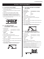
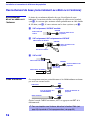
Trouble Light
AC Outlet Box
Ohmmeter
Cold-water Pip
e
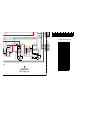
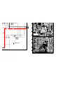
Figure A. Using an AC voltmeter to check AC leakage. Figure B. Checking for earth ground.
To Exposed Metal
Parts on Set
AC Voltmeter
(0.75 V)
Earth Ground
0
.15
µ
F
1.5
kΩ

— 7 —
KP-51WS500/57WS500/65WS500
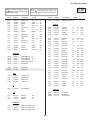
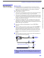
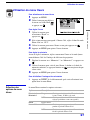
SELF-DIAGNOSTIC FUNCTION
The units in this manual contain a self-diagnostic function. If an error occurs, the STANDBY/TIMER LED will automatically begin to fl ash. The number
of times the LED fl ashes translates to a probable source of the problem. A defi nition of the STANDBY/TIMER LED fl ash indicators is listed in the
instruction manual for the user’s knowledge and reference. If an error symptom cannot be reproduced, the Remote Commander can be used to review
the failure occurrence data stored in memory to reveal past problems and how often these problems occur.
Diagnostic Test Indicators
When an error occurs, the STANDBY/TIMER LED will fl ash a set number of times to indicate the possible cause of the problem. If there is more than
one error, the LED will identify the fi rst of the problem areas.
Results for all of the following diagnostic items are displayed on screen. If the screen displays a “0”, no error has occurred.
Diagnostic Item
No. of times
STAND BY /
TIMER
lamp flashes
Probable Cause Location Detected Symptoms
Power does not turn on Does not light
• Power cord is not plugged in.
• Fuse is burned out (F6001). (G Board)
• Power does not come on.
• No power is supplied to the TV.
• AC Power supply is faulty.
+B overcurrent (OCP)* 2 times
• H.OUT (Q8024) is shorted. (D Board)
• +B PWM (Q8035, Q8038) is shorted.
(D Board)
• Power does not come on.
• Load on power line shorted.
+B overvoltage (OVP) 3 times
• IC501 is faulty. (G Board)
• IC5002 is faulty. (G Board)
• Has entered standby mode.
Vertical deflection stopped 4 times
•
±15V is not supplied. (D Board)
• IC8003 is faulty. (A Board)
• Has entered standby state after
horizontal raster.
• Vertical deflection pulse is
stopped.
• Power line is shorted, or
power supply is stopped.
White Balance Failure
(Not Balanced)
5times
• Video OUT (IC7101, IC7201, IC7301)
is faulty. (CR, CG, CB Boards)
• CRT drive (IC309) is faulty. (A Board)
• Screen (G2) is improperly adjusted. **
• No raster is generated.
• CRT Cathode current detection
reference pulse output is small.
Low B OCP/OVP
(Overcurrent/Overvoltage) ***
6times
• +5 line is overloaded. (A, B Boards)
• +5 line is shorted. (A, B Boards)
• No picture
Horizontal deflection stopped 7 times
• Q8035, Q8038 is shorted. (D Board)
High-voltage error 8 times
• T8005 is faulty. (D Board)
Audio error 9 times
•±19V line is shorted. (A, B Boards)
• IC708 is faulty. (A Board)
• PS701 or PS702 is opened.
(A Board)
• No sound
* If a +B overcurrent is detected, stoppage of the vertical deflection is detected simultaneously. The symptom that is diagnosed
first by the microcontroller is displayed on the screen.
** Refer to Screen (G2) Adjustments in Section 2-2 of this manual
*** If TIMER or STAND BY indicator blinks six (6) times, unplug the unit and wait 10 minutes before performing the adjustment.
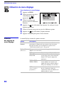
Self Diagnosis
Supported model

— 8 —
KP-51WS500/57WS500/65WS500
Display of Standby/Timer LED Flash Count
Lamp OFF :
3.0 seconds
Lamp ON : 0.3 seconds
Lamp OFF : 0.3 seconds
* One blink is not used for self-diagnosis.
• EXAMPLE
<Diagnosis Items> <Number of Blinks>
• +B overcurrent 2 times
• +B overvoltage 3 times
• Vertical deflection stop 4 times
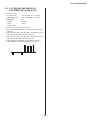
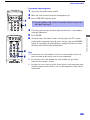
< FRONT PANEL >
TIMER/STAND BY indicator
Release of TIMER STAND BY indicator blinking
The TIMER/STANDBY indicator blinking display is released by turning OFF the power switch on the TV main unit or removing the plug from the
power.
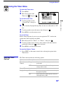
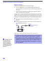
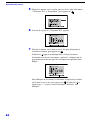
Self-Diagnosis Screen Displays
In cases of malfunctions where it is not possible to determine the symptom such as when the power goes off occasionally or when the screen
disappears occasionally, there is a screen display on whether the malfunction occurred or not in the past (and whether the detection circuit operated
or not) in order to allow confi rmation.
Screen Display Method
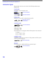
Quickly press the remote command button in the following order from the standby state.
Display
Channel
5
Sound Volume*
_
Power ON
*Note that this differs from entering the service mode (sound volume
+
)
SELF DIAGNOSIS
2 : +B OCP N/A
3 : +B OVP N/A
4 : V STOP 0
5 : AKB 1
10 : WDT 24
Numeral "0" means that no fault
was detected.
Numeral "1" means a fault was detected
one time or more
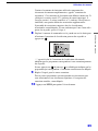
Self-Diagnosis Screen Display
The results display is not automatically cleared. In case of repairs and after repairs, check the self-diagnosis screen and be sure to return the
results display to “ 0 ”.
If the results display is not returned to “ 0 ” it will not be possible to judge a new malfunction after completing repairs.
Method of Clearing Results Display
1. Power off (Set to the standby mode.)
2.
Display
Channel
5
Sound Volume
+
Power ON (Service Mode)
3. Channel
8
ENTER
(Test reset = Factory preset condition)
Method of Ending Self Diagnosis Screen
When ending the self-diagnosis screen completely, turn the power switch OFF on the remote commander or the main unit.

— 9 —
KP-51WS500/57WS500/65WS500
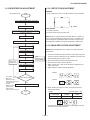
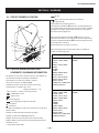
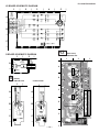
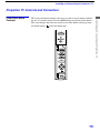
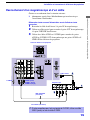
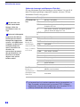
Self-Diagnosis Function Operation
OCP Low B and +B line detect DET SHORT, and shut-down POWER ON RELAY.
Reset by turning power on/off. In case of +B is loaded approx. 1.5A or more, microcomputer detects it via
IC5005.
OVP In case of +B becomes approx. 150V or more, POWER ON RELAY shuts down and microcomputer detects it via
IC5005.
Reset by turning power on/off just the same as OCP.
Low B Occurs when set +5V is out
V Stop In the case of the V Drive disappearing,
Q8001
Q8001 detects it and shuts-down the POWER ON RELAY. The microcomputer detects it and
causes the LED to blink.
AKB IK detection. Makes LED blink when microcomputer doesn’t detect IK, returns of
IC309 (CXA2150AQ) 20 seconds or more.
H Stop In case H DRIVE disappears,
Q378
Q378 detects it and shuts-down POWER ON RELAY.
Microcomputer receives H Stop data from
Q378
Q378 and makes the LED blink.
HV Stop In case HV becomes 33kV or more,
IC8006 detects it and shuts-down POWER ON RELAY.
The microcomputer makes the LED blink.
Audio In case of DC component overlaps the output of Audio Amp., the microcomputer detects it and shuts-down POWER ON RELAY.
The microcomputer makes the LED blink.
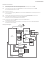
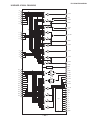
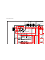
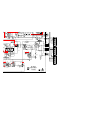
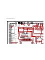
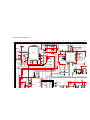
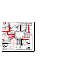
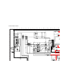
Self-Diagnosis Block Diagram
49
53
43 244544
31
28
29
25
58
35
34
5. AKB
5. AKB
4. V STOP
3. OVP
2. OCP
6. LOW B
8. HV.STOP
9. Audio
IC704
MAIN-CPU
IC309
CXA2150AQ
Y/C JUNGLE
D9101
TIMER/STANDBY
R765
IC702
EEPROM
IC703
EEPROM
Q714
+5V DETECT
Q378
H PULSE
Detector
IC8006
HV Detector
Q8001
V Pulse Detector
IC5005
OVP Buffer
OCP Buffer
C Board
DC Detect
IC8003
V Drive
IC708
6. H STOP
BUS
26
30
OVP DETECT
OCP DETECT
Audio AMP

— 10 —
KP-51WS500/57WS500/65WS500
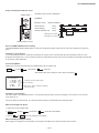
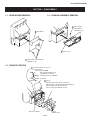
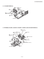
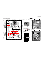
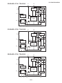
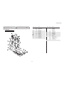
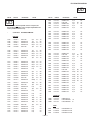
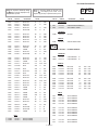
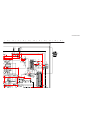
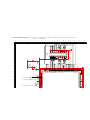
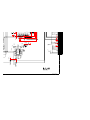
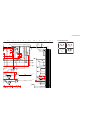
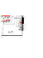
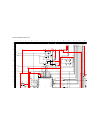
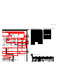
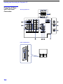
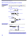
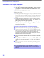
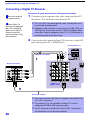
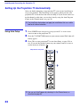
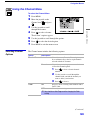
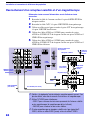
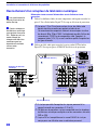
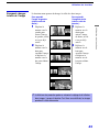
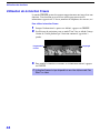
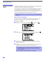
1-1. REAR BOARD REMOVAL 1-2. CHASSIS ASSEMBLY REMOVAL
SECTION 1: DISASSEMBLY
1-3. SERVICE POSITION
Nine Screws, dome washer
HEX tap 4 x 20
Rear board
2
1
Three screws,
dome washer
HEX tap 4 x 20
Chassis assy
2
1
From V board CN9001.
(The extension cable is not
supplied because of the
countermeasure for radiation.)
D board
CN17, 18, and 19
A board
Covers
Remove covers from chassis assembly
with pliers when checking printed circuit boards.
After checking, turn the covers over
and re-secure them with the screws.
Screws
(+BVTP 3x12)
Chassis assembly
Disconnect CN17, 18, and 19
on the A board.
1
2

— 11 —
KP-51WS500/57WS500/65WS500
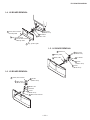
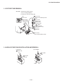
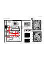
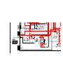
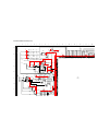
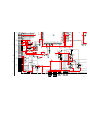
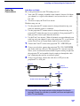
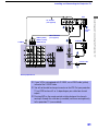
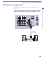
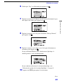
1-4. H2 BOARD REMOVAL
1-5. H1 BOARD REMOVAL
Screw, dome washer
HEX tap 4x20
Screw, dome washer
HEX tap 4x20
Six screws
(+BVTP 4x12
)
Cap, speaker grille
Cap, speaker grille
H2 board
Button, multi
2
1
2
1
5
4
3
Two screws
(+BVTP 4x12)
Screw
(+BVTP 3x12
)
H1 board
Button, power
Bracket H1
Screw
(+BVTP 4x12)
Guide, LED
7
6
2
1
4
3
5
1-6. H3 BOARD REMOVAL
Screws
(+BVTP 4x12)
Holder, front teminal
Bracket, H3
Screw
(+BVTP 3x12)
Two screws
(+BVTP 3x12)
Door, front terminal
H3 board
2
1
4
7
6
5
3

— 12 —
KP-51WS500/57WS500/65WS500
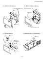
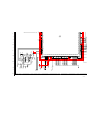
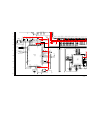
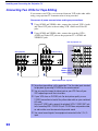
1-7. MIRROR COVER REMOVAL 1-8. BEZNET ASSEMBLY REMOVAL
Mirror cover
Twenty three screws,
dome washer HEX tap 4x20
1
2
Beznet assy
Screws,
dome washer HEX tap 4x20
Screws,
dome washer HEX tap 4x20
2
3
1
1-9. S BOARD REMOVAL
L screen holder
Claws
S board
Sensor
bracket (B)
Two screws
(+BVTP 4x12)
Four screws
(+BVTP 4x12)
Two screws
(+BVTP 4x12)
Sensor
bracket (A)
7
6
5
3
1
2
4
1-10. AD BOARD AND B BOARD REMOVAL
B board
AD board
Main bracket
1
1

— 13 —
KP-51WS500/57WS500/65WS500
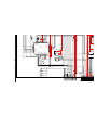
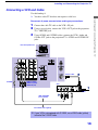
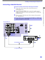
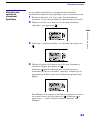
1-11. G BOARD REMOVAL
1-12. TERMINAL BOARD, A BOARD, D BOARD, U BOARD, AND UD BOARD REMOVAL
G board
Bracket G
Claws
Claw
Claw
Main bracket
Four screws
(+BVTP 3x12)
screw
(+BVTP 4x12)
2
2
3
2
1
5
4
D board
A board
Terminal board
Claws
Main bracket
U board
Two screws
(+BVTP 4x20 dome washer)
Screws
(+BVTP 3x12)
Six screws
(+BVTP 3x12)
Five screws
(+BVTP 3x12)
8
6
6
7
5
4
2
1
1
5
Two screws
(+BVTP 3x12)
3
UD board

— 14 —
KP-51WS500/57WS500/65WS500
1-13. PICTURE TUBE REMOVAL
Two screws
(+BVTP 3x12)
Four screws
(+BVTP 4x12)
Picture tube
Picture tube
Deflection yoke
Neck assy
CR board
V board
Lens
Lens
Four screws,
dome washer
HEX tap 4x20
Four screws,
dome washer HEX tap 4x20
Four screws,
dome washer HEX tap 4x20
CAUTION Removing the arrow-marked
screws is strictly prohibited.
If removed, it may cause liquid spill.
2
4
5
11
12
10
3
9
8
7
6
1
1-14. HIGH-VOLTAGE CABLE INSTALLATION AND REMOVAL
(1) Removal
Rubber cap
HV cable
turn 90°
HV cable
Gutter
Hook
(2) Installation
1
2
1

— 15 —
KP-51WS500/57WS500/65WS500
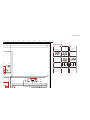
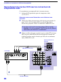
SECTION 2: SET-UP ADJUSTMENTS
2-1. SCREEN VOLTAGE ADJUSTMENT
(COARSE ADJUSTMENT)
1. Receive the Monoscope signal..
2. Set BRIGHTNESS to 50% and PICTURE to minimum.
3. Turn the red VR on the focus block all the way to the left and then
gradually turn it to the right until the retrace line is barely visible.
4. Gradually turn the control to the left until the retrace line disappears.
R G B
SCREEN
R G B
FOCUS
FOCUS Block
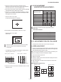
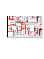
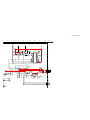
2-2. SCREEN (G2) ADJUSTMENT
(FINE ADJUSTMENT)
If the jig described below is available, it is recommended that the G2
Fine Mode Adjustment be performed to set the screen controls to their
optimal condition. If desired, you can build the jig illustrated below,
using 3-watt resistors. Please note that if the proper voltage is not
obtained with the listed resistor’s values, then increase or decrease one
of the values in the resistor network to obtain the correct voltage.
1. Select VIDEO-1 mode no signal applied (the screen must be black).
2. Connect the G2 JIG.
3. SW on JIG.
4. Connect an oscilloscope to the TP7101(KR), TP7202(KG) and
TP7301(KB) of CR board, CG board, and CB board.
5. Adjust red, green, and blue screen voltage to 177.5+/-0.5V with screen
VR on the focus block.
177.5V +/- 0.5V
G2 JIG
TP7202
(210V)
TO CG BOARD
GND
3.3k 3.9k 5.6k 6.8k
SW
K
GND
pedestal level
All resistors are 3W type
2-3. DEFLECTION YOKE TILT ADJUSTMENT
1. Connect the color bar generator monoscope pattern to Video 1 input.
2. Cover the red and blue CRT lenses with lens caps to allow only green
to show (or use the method shown in the note below for turning off the
CRTs individually without using lens caps).
3. Loosen the CRT’s deß ection yoke set screw and align the tilt of
the deß ection yoke so that the horizontal bars at the center of the
monoscope pattern are horizontal.
4. After aligning the deß ection yoke fasten it securely to the
funnel-shaped portion (neck) of the CRT.
The tilt of the deß ection yoke is aligned in the mode.
5. Cover the green and blue CRT lenses with lens caps to allow only
green to show (or use the method shown in the note below for turning
off the CRTs individually without using lens caps), then repeat steps
3 and 4 for the red CRT.
Cover the green and red CRT lenses with lens caps to allow only
green to show (or use the method shown in the note below for turning
off the CRTs individually without using lens caps), then repeat steps
3 and 4 for the blue CRT.
Note: If lens caps are unavailable, you can cut off the unnecessary color
beams by controlling the service mode 2150P-2 1 RGBS.
2-pole magnet
4-pole magnet
Deflection yoke
Anode cap
Centering magnet

— 16 —
KP-51WS500/57WS500/65WS500
2-4. FOCUS LENS ADJUSTMENT
In this adjustment, use the remote commander while in service mode.
For details on the usage of the service mode and the remote
commander, please refer to section
2-10. ELECTRICAL ADJUSTMENTS BY REMOTE COMMANDER.
1. Loosen the lens screw.
2. Cover the red and blue CRT lenses with lens caps to allow only green
to show (or use the method shown in the note below for turning off the
CRTs individually without using lens caps).
3. Turn the green lens to adjust to the optimum focus point with the
crosshatch signal.
4. Tighten the lens screw.
5. Cover the green and blue CRT lenses with the lens caps to allow only
red to show (or use the method shown in the note below for turning off
the CRTs individually without using lens caps).
6. Turn the red lens to adjust to the optimum focus point with the
crosshatch signal.
7. Tighten the lens screw.
8. Cover the green and red CRT lenses with the lens caps to allow only
blue to show (or use the method shown in the note below for turning
off the CRTs individually without using lens caps).
9. Turn the blue lens to adjust to the optimum focus point with the
crosshatch signal.
10. Tighten the lens screw.
11. After adjusting the items:
2-5. FOCUS VR ADJUSTMENT,
2-6. 2-POLE MAGNET ADJUSTMENT,
2-8. 4-POLE MAGNET ADJUSTMENT,
reconÞ rm the optimum focus point and adjust again if necessary.
* Every time 6 is pressed, the test signal changes to:
“crosshatch+video signal” → “crosshatch+borderline(black)” →
”crosshatch(black)” → “dots(black)” → off
Test Signal
Note: If lens caps are unavailable, you can cut off the unnecessary color
beams by controlling the service mode 2150P-2 1 RGBS.
2-5. FOCUS VR ADJUSTMENT
1. Set generator to crosshatch.
2. Cover the red and blue CRT lenses with lens caps to allow only green
to show (or use the method shown in the note below for turning off the
CRTs individually without using lens caps).
3. Turn the green focus VR on the focus block to adjust to the optimum
focus point with the crosshatch signal.
4. Cover the green and blue picture lenses with lens caps to allow only
red to show (or use the method shown in the note below for turning off
the CRTs individually without using lens caps).
5. Turn the red focus VR on the focus block to adjust to the optimum
focus point with the crosshatch signal.
6. Cover the green and red picture lenses with lens caps to allow only
blue to show (or use the method shown in the note below for turning
off the CRTs individually without using lens caps).
7. Turn the blue focus VR on the focus block to adjust to the optimum
focus point with the crosshatch signal.
8. After adjusting the items:
2-4. FOCUS LENS ADJUSTMENT,
2-6. 2-POLE MAGNET ADJUSTMENT,
2-8. 4-POLE MAGNET ADJUSTMENT,
reconÞ rm the optimum focus point and adjust again if necessary.
Note: If lens caps are unavailable, you can cut off the unnecessary color
beams by controlling the service mode 2150P-2 1 RGBS.
A
B
Lens
Minimize both A and B.
Center of crosshatch
Scanning line visible.

— 17 —
KP-51WS500/57WS500/65WS500
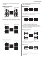
2-6. 2-POLE MAGNET AND CENTERING
MAGNET ADJUSTMENT
1. Set the picture mode to PRO and picture to MAX.
2. Either select the PJED Test Pattern dot hatch signal or apply an
external dot signal.
3. Cover the red and blue CRT lenses with lens caps to allow only green
to show (or use the method shown in the note below for turning off the
CRTs individually without using lens caps).
4. Turn the focus VR on the focus block to the left (counter clockwise)
and set it to overfocus to enlarge the spot.
5. Adjust the CRT’s 2-pole magnet so that the small bright spot is in
the center.
6. Align the focus VR on the focus block and set it for the best focus.
7. Apply a Monoscope signal to the set.
8. Adjust the H-CENTERING and V-CENTERING roughly by the
centering magnets.
9. Check 2-pole magnet adjustment. If necessary repeat steps 1-6.
10. Repeat steps 1 through 9 for the red CRT covering the
green and blue CRT lenses with lens caps to allow only
red to show (or use the method shown in the note below
for turning off the CRTs individually without using lens caps) and
adjust the red focus control on the focus block.
11. Repeat steps 1 through 9 for the blue CRT covering the
red and green CRT lenses with lens caps to allow only
blue to show (or use the method shown in the note below
for turning off the CRTs individually without using lens caps) and
adjust the blue focus control on the focus block.
Note: If lens caps are unavailable, you can cut off the unnecessary color
beams by controlling the service mode 2150P-2 1 RGBS.
2-7. CENTERING MAGNET ADJUSTMENT
Not required - Combined with 2-6 2-Pole And Centering Magnet
Adjustment.
2-8. 4-POLE MAGNET ADJUSTMENT
1. Set the picture mode to PRO and picture to MAX.
2. Receive the Dot signal.
3. Cover the red and blue CRT lenses with lens caps to allow only green
to show (or use the method shown in the note below for turning off the
CRTs individually without using lens caps).
4. Turn the (green) focus VR on the focus block to the right (clockwise)
and set it to under-focus to reduce the spot.
5. Adjust the 4-pole magnet so that the small spot in the center of the
screen becomes round for green and red.
6. Adjust the blue spot to an oval shape X:Y=1:1.2
Note: If lens caps are unavailable, you can cut off the unnecessary color
beams by controlling the service mode 2150P-2 1 RGBS.
x
y
x : y = 1:1 (Green, Red)
Use the center dot
2-9. BLUE DEFOCUS ADJUSTMENT
1. Setup: Apply a Dot Hatch Signal and set the mode to Pro Mode.
Change the color temperature to Cool in the user’s menu.
2. Cover the red and green CRT lenses with lens caps to allow only blue
to show (or use the method shown in the note below for turning off the
CRTs individually without using lens caps).
4. Turn the blue focus VR on the focus block to the right (clockwise) to
make the round dot oval.
D1
Blue
D1:D2 = 1:1.2
D2
5. Check the ß are with a high luminance signal to make sure the ß are is
minimal while the bright spot is located in the center, If not, readjust
the 2 and 4-pole magnets.
6. Check for uniformity on a 100% IRE to an all white signal.
Note: If lens caps are unavailable, you can cut off the unnecessary color
beams by controlling the service mode 2150P-2 1 RGBS.

— 18 —
KP-51WS500/57WS500/65WS500
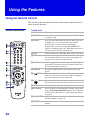
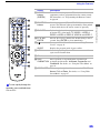
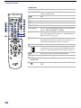
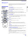
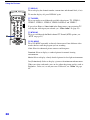
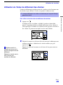
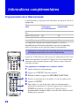
2-10. ELECTRICAL ADJUSTMENTS BY
REMOTE COMMANDER
All of the circuit adjustments can be made by using the remote
commander (RM-Y909).
NOTE : The following test equipment is required:
1. Pattern Generator (with component outputs)
2. Frequency counter
3. Digital multimeter
4. Audio oscillator
2-10-1.METHOD OF ENTERING THE SERVICE
ADJUSTMENT MODE
SERVICE MODE PROCEDURE
1. TV must be in Standby mode. (Power off)
2. Press “DISPLAY”, “5”, “VOL +”, then “POWER” on the remote
commander.
(Press each button within 1 second of pressing the previous button.)
SERVICE MODE ADJUSTMENT
Data
WSL : XXX
0 0
3D-COMB
NRMD
F / A FLAG : XXXXXXXX
CBA FLAG : XXXXXXXX
SERVICE
TV
Item NO.
Adjustment Item
Category
3. The screen displays the item being adjusted within that category.
4. Press 1 or 4 on the remote commander to select the adjustment item.
5. Press 3 or 6 on the remote commander to change the data.
6. Press 2 or 5 on the remote commander to select the adjustment
category.
Every time you press 2 (Category up), service mode changes in the
order shown below:
3D-COMB
2103-1
2103-2
2150P-1
2150P-2
2150P-3
2150D-1
2150D-3
AP
TRUS
2151
OP
ID
PJE
2150D-2
2150P-4
CCD
ID-1
OSD
SNNR
DLBY
MID1
MID2
MID3
MID5
7. If you want to go back to the most recently saved value, press “0”
then “ENTER” to read the memory.
8. Press “MUTING” then “ENTER” to write the new adjustment data into
memory.
9. When you want to exit the service mode, turn the power off.
Note: Press “8” then “ENTER” on the remote commander to restore the
factory settings for user controls and channel memories (this will also
turn set off and then on to exit the service mode).
2-10-2.MEMORY WRITE CONFIRMATION
METHOD
1. After adjustment, turn the power off with the remote commander.
2. Turn the power ON and set to service mode.
3. Cycle through the adjusted items again and confi rm that the
adjustments were saved.
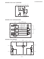
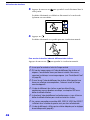
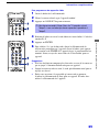
2-10-3.ADJUSTING BUTTONS AND
INDICATOR
Note: When the PJE mode (which displays an internally generated
signal) is activated, several buttons on the remote commander will have
different functions than the ones listed below. Therefore, when in the PJE
mode, refer to section 2-12-3 for button functions.
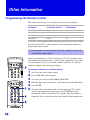
MUTING
Category up
Adjustment
item up
Adjustment
item down
ENTER
Data Down
Data Up
DISPLAY
POWER
VOLUME +
RM-Y909
Category
down

— 19 —
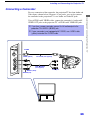
KP-51WS500/57WS500/65WS500
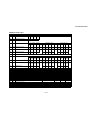
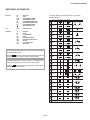
SERVICE DATA LISTS 2-11
11. APPENDIX
3D-COMB uPD64082
Re
g
.No &Nam
e
FUNCTION
0 NRMD
1 YAPS
2 CLKS
3 NSDS
4 MSS
5 KILS
6 CDL
7 DYCO
8 DYGA
9 DCCO
10 DCGA
11
YNRL
12
CNRL
13 VTRH
14 VTRR
15 LDSR
16
VAPG
17 VAPI
18 YPET
19 YPFG
20
YHCO
Note: YHCO & YHCG are defined
21 YHCG directl
y
b
y
SNNR data.
22
HSSL
23 VSSL
24 ADCL
25 D2GA
26 KILR
Y output high frequency component corin
g
Y output high frequency component coring gain
ADC clock dela
y
Hsync slice level
Vsync slice level
V-aperture compensation convergence poin
t
Y peaking filter center frequenc
y
Y peaking filter gain
Sensitivity for Hsysnc non-standard signal detection
Sensitivity for frame non-standard signal detection
V-aperture compensation gain
Hysteresis for Hsysnc non-standard signal detection
Operation mode settin
g
Y-output correction
System clock setting
DC detection gain
Frame recursive YNR nonlinear filter limit level
Frame recursive CNR nonlinear filter limit level
Selection for standard/non-standard signal processin
g
Selection for inter-frame/inter-line processin
g
Killer processing selection
C-signal phase with respect to the Y-signa
l
DY detection coring level
DY detection gain
DC detection coring level
4
2
10
5
NRMD=2
5
2
10
5
0
0
1
5
Non-standard
1
NRMD=0 NRMD=1
Video1-4
0
0
1
3
RF
Standard Standard Non-standard
00
0
SNNR=1
NRMD=0 NRMD=1
4
3
Moving detection gain
Killer detection reference
NRMD=3
5
5
1
SNNR=2
1
2
0
0
1
0
3
1
4
3
4
SNNR=3
2
SNNR=1
3
10
2
5
SNNR=2
0
10
1(
VM=of
f
0
0
0
0
1
3
SNNR=0
0
0
Svideo
RF/Video1-4 Svideo
Non-standardStandard Non-standard Standard
33
3
RF/Video1-4
0
1
Video1-4RF
1
1
2
SNNR=0
2
8
NRMD=3
VM=Lo
w
VM=Mid VM=High
Video5,6,
7
NRMD=2
1
1
8
1
2
SNNR=3
12
1
1
1
1
0
5
0

— 20 —
KP-51WS500/57WS500/65WS500
SERVICE DATA LISTS
3D-COMB uPD64082
Re
g
.No &Nam
e
FUNCTION
27
OP
28
NR1
29
NR2
30 WSL
31 HPLL
32 BPLL
33 FSCF
34
PLLF
35 CC3N
36 HDP
37
BGPS
38 BGPW
39 TEST
40 WSC
41 LIND
42 PFGO
#16 VAPG
NTSC-YCT CXA2103-1
Re
g
.No &Nam
e
FUNCTION
0
YLE
V
1 CLE
V
2 SCON
3 SCOL
4
SHUE
5 YDL
Y
6 SHAP
7 SHF0
8
PREO
9 BPF0
10 BPFO
11 BPSW
12
TRAP
13
LPF
14
AFCG
15
CDMD
16 SSMD
17
HMSK
18
HALI
19
PPHA
H TIM phase adjustment vide
o
V countdown system mode selecto
r
H&Vsync slide level settin
g
Masking of macrovision signal on/of
f
H automatic adjustment on/of
f
Y block chroma trap filter on/of
f
Y Cb Cr-Output LPF on/of
f
AFC Loop gain
Sharpness pre/over-shoot ratio
Chroma band filter f0 settin
g
Chroma band filter O setting
Chroma band filter on/of
f
Y/C delay tim
e
Sharpness
Sharpness f0 selector
Sub contras
t
Sub colo
r
Sub hu
e
Y-Out gain
Cb&Cr-Out gain
RF/Video1-4
P&P Lef
t
-DRC
34
27
Amount of noise detection corin
g
DRC-M line-doubling setting for non-standard signal
s
* Not used
Fine adjustment of the system H-phase
Internal burst gate start position
Test bit * forbidden settin
g
Burst extraction gain
PLL loop gain
Selection if a line-comb filter C separation filter characteristic
SNNR control on/of
f
Noise level detection level data
H-PLL filte
r
Burst PLL filte
r
Option:Selection of comb filter&recursive n.reduction types
.
1
Noise reduction on/off 0
RF
SNNR=3
3
SNNR=1SNNR=0
0
SNNR=2
281
0
3
0
0
0
3
0
1
0
0
3
0
0
3
77
2
0
Video 5,6-480i
4
1
0
Video5,
6
0
3
0
3
01
0
0
1
Video7
0
3
CVideo4
Video5,6-480i Video7-480i
CVideo3
0
SVideo3
10
CVideo2 SVideo2
0
1
4
3
0
3
0
0
1
-DRC
Video5,6,
7
0
3
Video1-4
0
7
40
4
SNNR=2
0
1
RF
0
10
SNNR=1
0
Video1-4
Video1-4
1
0
0
1
5
Video5,6,
7
Video1-4
0
SNNR=3
0
RF
0
0
CVideo1 SVideo1
1
Read data
3
SNNR=0
P&P Lef
t
0
Video1-4
40
46
RF
4
3
0
5
3
0
1
3
3
0
1
0
1
0
1
0
-DRC
0
0
0
Svideo
00
P&P Lef
t
46
Video7-480i
RF
1
00
RF
3
0
1
7
La page est en cours de chargement...
La page est en cours de chargement...
La page est en cours de chargement...
La page est en cours de chargement...
La page est en cours de chargement...
La page est en cours de chargement...
La page est en cours de chargement...
La page est en cours de chargement...
La page est en cours de chargement...
La page est en cours de chargement...
La page est en cours de chargement...
La page est en cours de chargement...
La page est en cours de chargement...
La page est en cours de chargement...
La page est en cours de chargement...
La page est en cours de chargement...
La page est en cours de chargement...
La page est en cours de chargement...
La page est en cours de chargement...
La page est en cours de chargement...
La page est en cours de chargement...
La page est en cours de chargement...
La page est en cours de chargement...
La page est en cours de chargement...
La page est en cours de chargement...
La page est en cours de chargement...
La page est en cours de chargement...
La page est en cours de chargement...
La page est en cours de chargement...
La page est en cours de chargement...
La page est en cours de chargement...
La page est en cours de chargement...
La page est en cours de chargement...
La page est en cours de chargement...
La page est en cours de chargement...
La page est en cours de chargement...
La page est en cours de chargement...
La page est en cours de chargement...
La page est en cours de chargement...
La page est en cours de chargement...
La page est en cours de chargement...
La page est en cours de chargement...
La page est en cours de chargement...
La page est en cours de chargement...
La page est en cours de chargement...
La page est en cours de chargement...
La page est en cours de chargement...
La page est en cours de chargement...
La page est en cours de chargement...
La page est en cours de chargement...
La page est en cours de chargement...
La page est en cours de chargement...
La page est en cours de chargement...
La page est en cours de chargement...
La page est en cours de chargement...
La page est en cours de chargement...
La page est en cours de chargement...
La page est en cours de chargement...
La page est en cours de chargement...
La page est en cours de chargement...
La page est en cours de chargement...
La page est en cours de chargement...
La page est en cours de chargement...
La page est en cours de chargement...
La page est en cours de chargement...
La page est en cours de chargement...
La page est en cours de chargement...
La page est en cours de chargement...
La page est en cours de chargement...
La page est en cours de chargement...
La page est en cours de chargement...
La page est en cours de chargement...
La page est en cours de chargement...
La page est en cours de chargement...
La page est en cours de chargement...
La page est en cours de chargement...
La page est en cours de chargement...
La page est en cours de chargement...
La page est en cours de chargement...
La page est en cours de chargement...
La page est en cours de chargement...
La page est en cours de chargement...
La page est en cours de chargement...
La page est en cours de chargement...
La page est en cours de chargement...
La page est en cours de chargement...
La page est en cours de chargement...
La page est en cours de chargement...
La page est en cours de chargement...
La page est en cours de chargement...
La page est en cours de chargement...
La page est en cours de chargement...
La page est en cours de chargement...
La page est en cours de chargement...
La page est en cours de chargement...
La page est en cours de chargement...
La page est en cours de chargement...
La page est en cours de chargement...
La page est en cours de chargement...
La page est en cours de chargement...
La page est en cours de chargement...
La page est en cours de chargement...
La page est en cours de chargement...
La page est en cours de chargement...
La page est en cours de chargement...
La page est en cours de chargement...
La page est en cours de chargement...
La page est en cours de chargement...
La page est en cours de chargement...
La page est en cours de chargement...
La page est en cours de chargement...
La page est en cours de chargement...
La page est en cours de chargement...
La page est en cours de chargement...
La page est en cours de chargement...
La page est en cours de chargement...
La page est en cours de chargement...
La page est en cours de chargement...
La page est en cours de chargement...
La page est en cours de chargement...
La page est en cours de chargement...
La page est en cours de chargement...
La page est en cours de chargement...
La page est en cours de chargement...
La page est en cours de chargement...
La page est en cours de chargement...
La page est en cours de chargement...
La page est en cours de chargement...
La page est en cours de chargement...
La page est en cours de chargement...
La page est en cours de chargement...
La page est en cours de chargement...
La page est en cours de chargement...
La page est en cours de chargement...
La page est en cours de chargement...
La page est en cours de chargement...
La page est en cours de chargement...
La page est en cours de chargement...
La page est en cours de chargement...
La page est en cours de chargement...
La page est en cours de chargement...
La page est en cours de chargement...
La page est en cours de chargement...
La page est en cours de chargement...
La page est en cours de chargement...
La page est en cours de chargement...
La page est en cours de chargement...
La page est en cours de chargement...
La page est en cours de chargement...
La page est en cours de chargement...
La page est en cours de chargement...
La page est en cours de chargement...
La page est en cours de chargement...
La page est en cours de chargement...
La page est en cours de chargement...
La page est en cours de chargement...
La page est en cours de chargement...
La page est en cours de chargement...
La page est en cours de chargement...
La page est en cours de chargement...
La page est en cours de chargement...
La page est en cours de chargement...
La page est en cours de chargement...
La page est en cours de chargement...
La page est en cours de chargement...
La page est en cours de chargement...
La page est en cours de chargement...
La page est en cours de chargement...
La page est en cours de chargement...
La page est en cours de chargement...
La page est en cours de chargement...
La page est en cours de chargement...
La page est en cours de chargement...
La page est en cours de chargement...
La page est en cours de chargement...
La page est en cours de chargement...
La page est en cours de chargement...
La page est en cours de chargement...
La page est en cours de chargement...
La page est en cours de chargement...
La page est en cours de chargement...
La page est en cours de chargement...
La page est en cours de chargement...
La page est en cours de chargement...
La page est en cours de chargement...
La page est en cours de chargement...
La page est en cours de chargement...
La page est en cours de chargement...
La page est en cours de chargement...
La page est en cours de chargement...
La page est en cours de chargement...
La page est en cours de chargement...
La page est en cours de chargement...
La page est en cours de chargement...
La page est en cours de chargement...
La page est en cours de chargement...
La page est en cours de chargement...
La page est en cours de chargement...
La page est en cours de chargement...
La page est en cours de chargement...
La page est en cours de chargement...
La page est en cours de chargement...
La page est en cours de chargement...
La page est en cours de chargement...
La page est en cours de chargement...
La page est en cours de chargement...
La page est en cours de chargement...
La page est en cours de chargement...
La page est en cours de chargement...
La page est en cours de chargement...
La page est en cours de chargement...
La page est en cours de chargement...
La page est en cours de chargement...
La page est en cours de chargement...
La page est en cours de chargement...
La page est en cours de chargement...
La page est en cours de chargement...
La page est en cours de chargement...
La page est en cours de chargement...
La page est en cours de chargement...
La page est en cours de chargement...
La page est en cours de chargement...
La page est en cours de chargement...
La page est en cours de chargement...
La page est en cours de chargement...
La page est en cours de chargement...
La page est en cours de chargement...
La page est en cours de chargement...
La page est en cours de chargement...
La page est en cours de chargement...
La page est en cours de chargement...
La page est en cours de chargement...
La page est en cours de chargement...
La page est en cours de chargement...
La page est en cours de chargement...
La page est en cours de chargement...
La page est en cours de chargement...
La page est en cours de chargement...
La page est en cours de chargement...
La page est en cours de chargement...
La page est en cours de chargement...
La page est en cours de chargement...
La page est en cours de chargement...
La page est en cours de chargement...
La page est en cours de chargement...
La page est en cours de chargement...
La page est en cours de chargement...
La page est en cours de chargement...
La page est en cours de chargement...
La page est en cours de chargement...
La page est en cours de chargement...
La page est en cours de chargement...
La page est en cours de chargement...
La page est en cours de chargement...
La page est en cours de chargement...
La page est en cours de chargement...
La page est en cours de chargement...
La page est en cours de chargement...
La page est en cours de chargement...
La page est en cours de chargement...
La page est en cours de chargement...
La page est en cours de chargement...
La page est en cours de chargement...
La page est en cours de chargement...
La page est en cours de chargement...
La page est en cours de chargement...
La page est en cours de chargement...
La page est en cours de chargement...
La page est en cours de chargement...
La page est en cours de chargement...
La page est en cours de chargement...
La page est en cours de chargement...
La page est en cours de chargement...
La page est en cours de chargement...
La page est en cours de chargement...
La page est en cours de chargement...
La page est en cours de chargement...
La page est en cours de chargement...
La page est en cours de chargement...
La page est en cours de chargement...
La page est en cours de chargement...
La page est en cours de chargement...
La page est en cours de chargement...
La page est en cours de chargement...
La page est en cours de chargement...
La page est en cours de chargement...
La page est en cours de chargement...
La page est en cours de chargement...
La page est en cours de chargement...
La page est en cours de chargement...
La page est en cours de chargement...
La page est en cours de chargement...
La page est en cours de chargement...
La page est en cours de chargement...
La page est en cours de chargement...
La page est en cours de chargement...
La page est en cours de chargement...
La page est en cours de chargement...
La page est en cours de chargement...
La page est en cours de chargement...
La page est en cours de chargement...
La page est en cours de chargement...
La page est en cours de chargement...
La page est en cours de chargement...
La page est en cours de chargement...
La page est en cours de chargement...
La page est en cours de chargement...
La page est en cours de chargement...
La page est en cours de chargement...
La page est en cours de chargement...
La page est en cours de chargement...
La page est en cours de chargement...
La page est en cours de chargement...
La page est en cours de chargement...
La page est en cours de chargement...
La page est en cours de chargement...
La page est en cours de chargement...
La page est en cours de chargement...
La page est en cours de chargement...
La page est en cours de chargement...
La page est en cours de chargement...
La page est en cours de chargement...
La page est en cours de chargement...
La page est en cours de chargement...
La page est en cours de chargement...
La page est en cours de chargement...
La page est en cours de chargement...
La page est en cours de chargement...
-
 1
1
-
 2
2
-
 3
3
-
 4
4
-
 5
5
-
 6
6
-
 7
7
-
 8
8
-
 9
9
-
 10
10
-
 11
11
-
 12
12
-
 13
13
-
 14
14
-
 15
15
-
 16
16
-
 17
17
-
 18
18
-
 19
19
-
 20
20
-
 21
21
-
 22
22
-
 23
23
-
 24
24
-
 25
25
-
 26
26
-
 27
27
-
 28
28
-
 29
29
-
 30
30
-
 31
31
-
 32
32
-
 33
33
-
 34
34
-
 35
35
-
 36
36
-
 37
37
-
 38
38
-
 39
39
-
 40
40
-
 41
41
-
 42
42
-
 43
43
-
 44
44
-
 45
45
-
 46
46
-
 47
47
-
 48
48
-
 49
49
-
 50
50
-
 51
51
-
 52
52
-
 53
53
-
 54
54
-
 55
55
-
 56
56
-
 57
57
-
 58
58
-
 59
59
-
 60
60
-
 61
61
-
 62
62
-
 63
63
-
 64
64
-
 65
65
-
 66
66
-
 67
67
-
 68
68
-
 69
69
-
 70
70
-
 71
71
-
 72
72
-
 73
73
-
 74
74
-
 75
75
-
 76
76
-
 77
77
-
 78
78
-
 79
79
-
 80
80
-
 81
81
-
 82
82
-
 83
83
-
 84
84
-
 85
85
-
 86
86
-
 87
87
-
 88
88
-
 89
89
-
 90
90
-
 91
91
-
 92
92
-
 93
93
-
 94
94
-
 95
95
-
 96
96
-
 97
97
-
 98
98
-
 99
99
-
 100
100
-
 101
101
-
 102
102
-
 103
103
-
 104
104
-
 105
105
-
 106
106
-
 107
107
-
 108
108
-
 109
109
-
 110
110
-
 111
111
-
 112
112
-
 113
113
-
 114
114
-
 115
115
-
 116
116
-
 117
117
-
 118
118
-
 119
119
-
 120
120
-
 121
121
-
 122
122
-
 123
123
-
 124
124
-
 125
125
-
 126
126
-
 127
127
-
 128
128
-
 129
129
-
 130
130
-
 131
131
-
 132
132
-
 133
133
-
 134
134
-
 135
135
-
 136
136
-
 137
137
-
 138
138
-
 139
139
-
 140
140
-
 141
141
-
 142
142
-
 143
143
-
 144
144
-
 145
145
-
 146
146
-
 147
147
-
 148
148
-
 149
149
-
 150
150
-
 151
151
-
 152
152
-
 153
153
-
 154
154
-
 155
155
-
 156
156
-
 157
157
-
 158
158
-
 159
159
-
 160
160
-
 161
161
-
 162
162
-
 163
163
-
 164
164
-
 165
165
-
 166
166
-
 167
167
-
 168
168
-
 169
169
-
 170
170
-
 171
171
-
 172
172
-
 173
173
-
 174
174
-
 175
175
-
 176
176
-
 177
177
-
 178
178
-
 179
179
-
 180
180
-
 181
181
-
 182
182
-
 183
183
-
 184
184
-
 185
185
-
 186
186
-
 187
187
-
 188
188
-
 189
189
-
 190
190
-
 191
191
-
 192
192
-
 193
193
-
 194
194
-
 195
195
-
 196
196
-
 197
197
-
 198
198
-
 199
199
-
 200
200
-
 201
201
-
 202
202
-
 203
203
-
 204
204
-
 205
205
-
 206
206
-
 207
207
-
 208
208
-
 209
209
-
 210
210
-
 211
211
-
 212
212
-
 213
213
-
 214
214
-
 215
215
-
 216
216
-
 217
217
-
 218
218
-
 219
219
-
 220
220
-
 221
221
-
 222
222
-
 223
223
-
 224
224
-
 225
225
-
 226
226
-
 227
227
-
 228
228
-
 229
229
-
 230
230
-
 231
231
-
 232
232
-
 233
233
-
 234
234
-
 235
235
-
 236
236
-
 237
237
-
 238
238
-
 239
239
-
 240
240
-
 241
241
-
 242
242
-
 243
243
-
 244
244
-
 245
245
-
 246
246
-
 247
247
-
 248
248
-
 249
249
-
 250
250
-
 251
251
-
 252
252
-
 253
253
-
 254
254
-
 255
255
-
 256
256
-
 257
257
-
 258
258
-
 259
259
-
 260
260
-
 261
261
-
 262
262
-
 263
263
-
 264
264
-
 265
265
-
 266
266
-
 267
267
-
 268
268
-
 269
269
-
 270
270
-
 271
271
-
 272
272
-
 273
273
-
 274
274
-
 275
275
-
 276
276
-
 277
277
-
 278
278
-
 279
279
-
 280
280
-
 281
281
-
 282
282
-
 283
283
-
 284
284
-
 285
285
-
 286
286
-
 287
287
-
 288
288
-
 289
289
-
 290
290
-
 291
291
-
 292
292
-
 293
293
-
 294
294
-
 295
295
-
 296
296
-
 297
297
-
 298
298
-
 299
299
-
 300
300
-
 301
301
-
 302
302
-
 303
303
-
 304
304
-
 305
305
-
 306
306
-
 307
307
-
 308
308
-
 309
309
-
 310
310
-
 311
311
-
 312
312
-
 313
313
-
 314
314
-
 315
315
-
 316
316
-
 317
317
-
 318
318
-
 319
319
-
 320
320
-
 321
321
-
 322
322
-
 323
323
-
 324
324
-
 325
325
-
 326
326
-
 327
327
-
 328
328
-
 329
329
-
 330
330
-
 331
331
-
 332
332
-
 333
333
-
 334
334
-
 335
335
-
 336
336
-
 337
337
-
 338
338
-
 339
339
-
 340
340
-
 341
341
-
 342
342
-
 343
343
-
 344
344
-
 345
345
-
 346
346
-
 347
347
-
 348
348


Sony Hi-Scan KP-51WS500 Manuel utilisateur
- Taper
- Manuel utilisateur
- Ce manuel convient également à
Documents connexes
Autres documents
-
Hitachi 27CX01B Manuel utilisateur
-
Compaq NSZ2107STTUW Manuel utilisateur
-
Premier ctv-2641sr Manuel utilisateur
-
Kenwood LSK 300 Le manuel du propriétaire
-
Kyosho 31279 Le manuel du propriétaire
-
-
-
-
-