LMI XRD141-A76VCN7PN Guide de démarrage rapide
- Taper
- Guide de démarrage rapide

Excel
®
XR Series
Quick Start Guide
Manual No. : 54941
Revision : 02
Rev. Date : 08/2017
This quic
k start guide is only valid when used with the complete installation and operation manual.

1
EN
All Manuals:
support.lmipumps.com/Series/XR
(866) 433-6682 • (281) 359-8538 • [email protected] • www.novatech-usa.com

PRECAUTIONS
1
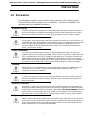
1.0 Precautions
The following precautions should be taken when working with LMI metering pumps.
Please read this section carefully prior to installation. Consult the installation and
operation manual for additional precautions.
Protective Clothing
ALWAYS wear protective clothing, face shield, safety glasses and gloves when working on or
near your metering pump. Additional precautions should be taken depending on the solution
being pumped. Refer to Safety Data Sheet (SDS) precautions from your solution supplier.
Water Pre-Prime
All LMI pumps are pre-primed with water when shipped from the factory. If your solution is not
compatible with water, disassemble the Pump Head Assembly. Thoroughly dry the pump head,
valves, O-rings, balls and diaphragm. Reassemble head assembly tightening screws in a
crisscross pattern. Refill the pump head with the solution to be pumped before priming the
pump. (This will aid in priming.)
Liquid Compatibility
CAUTION: The evaluation performed by ETL was tested with water only. The pumps are
certified to NSF 61 with: sodium hypochlorite (12.5%), sulfuric acid (98.5%), sodium hydroxide
(50%), and hydrochloric acid (30%). Determine if the materials of construction included in the
liquid handling portion of your pump are adequate for the solution (chemical) to be pumped.
Always refer to the solution supplier and the LMI Chemical Resistance Chart for compatibility of
your specific LMI metering pump. Contact your local LMI distributor for further information.
Plumbing
Always adhere to your local plumbing codes and requirements. Be sure installation does not
constitute a cross connection. Check local plumbing codes for guidelines. LMI is not
responsible for improper installations.
Over Pressure Protection
To ensure safe operation of the pump it is recommended that some type of safety / pressure-
relief valve be installed to protect the piping and other system components from failing due to
excessive pressure.
Electrical Connections
WARNING: To reduce the risk of electrical shock, the metering pump must be plugged into a
properly grounded grounding-type receptacle with ratings conforming to the data on the pump
control panel. The pump must be connected to a good ground. Do not use adapters! All wiring
must conform to local electrical codes. If the supply cord is damaged, it must be replaced by
the manufacturer, stocking distributor, or authorized repair center in order to avoid a hazard.
Retightening Components
Plastic materials will typically exhibit creep characteristics when under pressure over a period
of time and to insure a proper fit it may be necessary to retighten the head bolts periodically. To
insure proper operation, we recommend tightening the bolts to 25 inch-pounds after the first
week of operation and on a monthly basis thereafter.
(866) 433-6682 • (281) 359-8538 • [email protected] • www.novatech-usa.com

UNPACKING CHECK LIST & SPECIFICATIONS
2
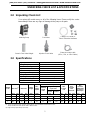
2.0 Unpacking Check List
Your carton will contain many or all of the following items. Please notify the carrier
immediately if there are any signs of damage to the pump or its parts.
Metering Pump
Foot Valve
Tubing (0 or 2 Rolls) &
Tube Connection Hardware
Ceramic Foot Valve Weight
Injection Check Valve
External Control Cable
(6 Pin, 5 Pin, or 4 Pin Cables)
3.0 Specifications
Ingress protection
IP65 / NEMA 4X
Voltage / Frequency
100-240 V / 50-60 Hz
Max. Current / Wattage
0.42 A / 42 W
Operation environment
Indoor
Process fluid temperature
-10°C to +40°C
Operating ambient temperature
-10°C to +40°C
Storage temperature
-40°C to +70°C
Operating humidity range
0-95% RH (Non-condensing)
Steady state accuracy
+/- 1%
Turndown
1000:1 (200:1 PTFE Seat, 500:1 FKM Seat)
Output
Code
Max. Flow
(1)
Max. Press
Stroke
Length
Max.
Stroke
Speed
Max. Viscosity
Max.
Suction
Lift
Max.
Suction
Inlet
Pressure
Min.
Pressure
Differential
(Suction to
Discharge)
Standard
Liquid
Ends
High Viscosity
Liquid Ends
Polymer
Other
Products
-
[GPH]
[l/h]
[psi]
[bar]
[mm]
[SPM]
[cP]
[ft]
[m]
[psi]
[bar]
[psi]
[bar]
2
5.6
21.2
175
(2)(3)
12
(2)(3)
3
151
50
1250
250
13.1
4
30
2
30
2
3
14.0
53.0
75
5
6
162
50
1250
250
13.1
4
30
2
30
2
4
18.0
68.1
50
3.5
3
144
50
1250
250
6.5
2
30
2
30
2
(1) Maximum flow rate at maximum pressure. Maximum flow rate may be higher at lower pressures.
(2) 175 psi (12 bar) max. with 1/4"x1/2" reinforced PVC hose or 6x12mm reinforced PVC hose;
150 psi (10 bar) max. with 3/8" PE tube or 8mm PE tube.
(3) High viscosity option 150 psi (10.3 bar).
(866) 433-6682 • (281) 359-8538 • [email protected] • www.novatech-usa.com

INSTALLATION
3
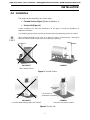
4.0 Installation
The pump can be mounted in one of two ways:
• Flooded Suction (Figure 1) [ideal installation]; or
• Suction Lift (Figure 2)
Suction conditions can affect the performance of the pump. Consult your distributor for
additional information.
Your metering pump must be mounted so that the suction and discharge valves are vertical.
When pumping downhill or into a low or no pressure system, a backpressure / anti-syphon
device should be installed to prevent over pumping or syphoning.
INCORRECT
False Flooded Suction
CORRECT
Figure 1: Flooded Suction
INCORRECT
Foot valve tilted sideways WILL NOT PRIME
CORRECT
Foot valve must remain vertical
Figure 2: Suction Lift
2 in (50 mm) for
Sediment Accumulation
Use Ceramic
Weight
(866) 433-6682 • (281) 359-8538 • [email protected] • www.novatech-usa.com

INSTALLATION
4
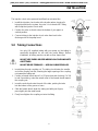
The injection check valve prevents backflow from a treated line.
1. Install the injection check valve at the location where chemical is
being injected into the system. Any size ½ inch female NPT fitting
will accept the injection check valve.
2. Position the valve so that it enters the bottom of your pipe in a
vertical position.
3. Connect tubing to the injection check valve then back to the
discharge side of the pump head.
5.0 Tubing Connections
Use only LMI supplied tubing with your pump, as the tubing is
specifically designed for use with the pump fittings. Before
installation, all tubing must be cut with a clean square end.
DO NOT USE PLIERS OR PIPE WRENCH ON COUPLING NUTS
OR FITTINGS.
DO NOT REUSE FERRULES — USE ONLY NEW FERRULES.
1. Insert tubing through coupling nut. The tubing should enter the smaller
end of the coupling nut first, orienting the larger opening of the coupling
nut toward the tubing end.
2. Position a female ferrule about 1 in (25 mm) from end of tubing. For 3/8
in and 8 mm tubing, orient the raised collar of the female ferrule toward
the coupling nut.
3. Insert the male ferrule onto the end of the tube, pushing the tube
into the bottom of the groove or base.
4. Slide the female ferrule down the tubing and with your fingers,
press tightly into the male ferrule.
5. Firmly hand tighten the coupling nut onto the fitting.
PTFE Tape
on Pipe
Attachment
Only
Pipe
Cross-Section
Injection
Check-Valve
Coupling Nut
Ferrule (Female)
Tube
3/8” or 8mm
Hose
1/4”x1/2” or 6x12mm
O-Ring
Fitting
Ferrule (Male)
Coupling Nut
Tube 1/2"
Ferrule (Female)
Ferrule (Male) / Fitting
(866) 433-6682 • (281) 359-8538 • [email protected] • www.novatech-usa.com

OPERATION
5
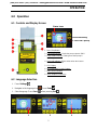
6.0 Operation
6.1 Controls and Display Screen
1. Start / Stop Button
2. Full Capacity Button: Sends the pump output to 100%.
3. Pump Status Indicator: Glows green when pump is
operating.
4. Low Level Indicator: Glows amber when tank sensor
detects a low fluid level.
5. LCD Display
6. Up / Down Multi-Function Buttons
7. Multi-Function Buttons
8. Input / Output Connector(s)
6.2 Language Selection
1. Press Settings .
2. Navigate to the language icon . Press Enter .
3. Select language. Press Save before pressing Exit .
1
2
3
Flow Rate Setting
% Full Flow Capacity
Status Icons
(866) 433-6682 • (281) 359-8538 • [email protected] • www.novatech-usa.com

OPERATION
6
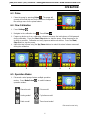
6.3 Prime
1. Prime the pump by pressing Prime . The pump will
operate at the flow rate and for the duration configured in
the settings menu for the prime feature.
6.4 Flow Calibration
1. Press Settings .
2. Navigate to the calibration icon . Press Enter .
3. Prepare a device such as a calibration column to measure the total volume of fluid pumped
during calibration. Press the Start / Stop button to start the pump. Allow the pump to run
as long as possible. Calibration accuracy improves with more strokes. Press the Start /
Stop button to stop the pump.
4. Adjust the total volume using the Up / Down buttons to match the actual volume measured
during the calibration.
6.5 Operation Modes
1. Enhanced control pumps feature multiple operation
modes. Press Mode Select to switch between
operation modes.
Manual mode
Pulse mode*
Analog mode*
Cycle timer mode*
Batch mode*
Timed event mode*
1
1
2
3
4
1
* Enhanced control only
(866) 433-6682 • (281) 359-8538 • [email protected] • www.novatech-usa.com

OPERATION
7
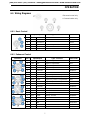
6.6 Wiring Diagrams
6.6.1 Basic Control
Connector
Pin #
Input/Output
Type - Function
Wire Color
1
-
No Connect
Red/White
2
-
No Connect
Red
3
-
No Connect
Green
4
DI1
Input
Digital - Programmable
Red/Yellow
5
-
Power 24V
Red/Black
6
-
GND
Red/Blue
6.6.2 Enhanced Control
Connector
Pin #
Input/Output
Type - Function
Wire Color
1
DI1
Input
Digital - Programmable
Red/White
2
DI2
Input
Digital - Programmable
Red
3
DI3
Input
Digital - Programmable
Green
4
DI4
Input
Digital - Programmable
Red/Yellow
5
-
Power 24V
Red/Black
6
-
GND
Red/Blue
1
DO1A
Output
Digital / Dry Contact - Programmable
Brown
2
DO1B
Output
Digital / Dry Contact - Programmable
White
3
DO2A
Output
Digital / Dry Contact - Programmable
Blue
4
DO2B
Output
Digital / Dry Contact - Programmable
Black
5
-
No Connect
1
-
Power 24V
Red/Black
2
AI1
Input
Analog - 0/20 mA
Red/White
3
-
Power 24V
Red
4
AI2
Input
Analog - 0/20 mA
Green
1
AO1
Output
Analog - 4/20 mA
Red/White
2
-
GND
Red
3
-
Power 24V
Green
4
-
GND
Red/Yellow
5
-
No Connect
Red/Black
6
-
No Connect
Red/Blue
* Enhanced control only
** Communications only
(866) 433-6682 • (281) 359-8538 • [email protected] • www.novatech-usa.com

OPERATION
8
6.6.3 Communications (same as enhanced, except for J3 and C)
Connector
Pin #
Input/Output
Type - Function
Wire Color
1
-
Ground
Red/Black
2
AI1
Input
Analog - 0/20 mA
Red/White
3
-
Ground
Red
4
AI2
Input
Analog - 0/20 mA
Green
C
1
-
-
VP (5V)
Blue
2
-
-
D0 (Negative Data Signal)
Green
3
-
-
DGND
White
4
-
-
D1 (Positive Data Signal)
Red
5
-
-
N/A
Bare
Thread: Shield (earth ground)
Thread
;
Shiled
-
No Connect
(866) 433-6682 • (281) 359-8538 • [email protected] • www.novatech-usa.com
sales@novatech-usa.com
www.novatech-usa.com
Tel: (866) 433-6682 Fax: (866) 433-6684
Tel: (281) 359-8538 Fax: (281) 359-0084

info@lmipumps.com
www.lmipumps.com
© 2017 Milton Roy, LLC
We are a proud member of Accudyne Industries, a leading global provider of precision-engineered,
process-critical, and technologically advanced flow control systems and industrial compressors.
Delivering consistently high levels of performance, we enable customers in the most important industries
and harshest environments around the world to accomplish their missions.
Nous sommes fiers d'être membre de Accudyne Industries, fournisseur mondial de pointe de systèmes
de régulation de débit et de compresseurs industriels de technologie avancée, d'ingénierie de précision
pour processus critiques. En maintenant régulièrement de hauts niveaux de performances, nous
permettons à nos clients dans les plus grandes industries et les environnements les plus difficiles
d'accomplir leurs missions dans le monde entier.
Wir sind Teil von Accudyne Industries, einem führenden weltweiten Anbieter von präzisionsgefertigten,
prozesskritischen und technologisch fortschrittlichen Strömungskontrollsystemen und
Industriekompressoren. Wir liefern konsistent hohe Leistung und ermöglichen es Kunden in den
wichtigsten Branchen und rauesten Umgebungen auf der ganzen Welt, ihre Mission zu erfüllen.
Siamo orgogliosi di far parte di Accudyne Industries, uno dei principali fornitori globali di impianti di
controllo della portata e di compressori industriali di alta precisione, per processi critici e
tecnologicamente avanzati. Assicurando livelli uniformemente elevati di prestazioni, permettiamo a clienti
di tutto il mondo, operanti nei comparti più importanti e negli ambienti più difficili, di conseguire la propria
missione.
Somos um membro orgulhoso da Accudyne Industries, líder global no fornecimento de sistemas de
controle de fluxo tecnologicamente avançados, com engenharia de precisão, processos críticos e
compressores industriais. Ao oferecer altos níveis de desempenho de forma constante, permitimos que
os clientes dos setores mais importantes e dos ambientes mais severos ao redor do mundo realizem
suas missões.
Somos un miembro orgulloso de Accudyne Industries, proveedor mundial líder de compresores
industriales y sistemas de control de flujo tecnológicamente avanzados de precisión, críticos para el
proceso. Al generar consistentemente altos niveles de desempeño, nosotros hacemos posible que los
clientes logren cumplir con sus misiones en las industrias más importantes y los ambientes más
rigurosos alrededor del mundo.
我们以作为
Accudyne Industries
公司的一员而骄傲,本公司是拥有精密工程、关键流程和领先技术的流量
控制系统和工业压缩机的全球供应商。
我们始终如一地交付优质的性能,使客户在世界上最重要的行业、
以及最恶劣的环境里都能圆满完成任务。
LMI is a registered trademark of Milton Roy, LLC
Excel is a registered trademark of Milton Roy, LLC
Excel est une marque de commerce de Milton Roy, LLC
Excel ist eine Marke von Milton Roy, LLC.
Excel è un marchio di fabbrica di Milton Roy, LLC
Excel é marca registrada da Milton Roy, LLC
Excel es una marca registrada de Milton Roy, LLC
Excel是 Milton Roy, LLC 的商标
(866) 433-6682 • (281) 359-8538 • [email protected] • www.novatech-usa.com
-
 1
1
-
 2
2
-
 3
3
-
 4
4
-
 5
5
-
 6
6
-
 7
7
-
 8
8
-
 9
9
-
 10
10
-
 11
11


LMI XRD141-A76VCN7PN Guide de démarrage rapide
- Taper
- Guide de démarrage rapide
dans d''autres langues
- italiano: LMI XRD141-A76VCN7PN Guida Rapida
- English: LMI XRD141-A76VCN7PN Quick start guide
Autres documents
-
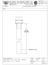 T & S Brass & Bronze Works B-0618-02 Fiche technique
-
Ohaus OHA-30134157 Le manuel du propriétaire
-
Ohaus 30268985 Le manuel du propriétaire
-
Ohaus 30253006 Guide de démarrage rapide
-
-
Ohaus 30428206 Le manuel du propriétaire
-
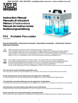 VELP Scientific VLP-F105A0117 Le manuel du propriétaire
-
-
-

