KitchenAid KWCU505WSS0 Le manuel du propriétaire
- Catégorie
- Hottes
- Taper
- Le manuel du propriétaire
Ce manuel convient également à

I_i|chen_kid ®
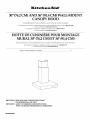
30" (76.2 CM) AND 36" (91.4 CM) WALL-MOUNT
CANOPY HOOD
For questions about features, operation/performance, parts, accessories or service, call: 1-800-422-1230
or visit our website at www,kitchenaid,com
In Canada, for assistance, installation and service, call: 1-800-807-6777
or visit our website at www,kitchenaid,ca
HO IIE DE CUISINIERE POUR MONTAGE
MURAL 30" (76,2 CM) ET 36" (91,4 CM)
Au Canada, pour assistance,installationou servicecomposez le1-800-807-6777
ou visiteznotresiteweb a www,Mtchenaid,ca
Table of Contents/Table des matieres ............................................................................. 2
IMPORTANT: READ AND SAVE THESE INSTRUCTIONS.
FOR RESIDENTIAL USE ONLY.
iMPORTANT : MRE ET CONSERVER CES iNSTRUCTiONS.
POUR UTILISATION Rf-=SIDENTIELLE UNIQUEMENT.
W10268948C

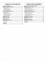
TABLEOF CONTENTS
RANGE HOOD SAFETY ................................................................. 3
INSTALLATION REQUIREMENTS ................................................ 5
Tools and Parts ............................................................................ 5
Location Requirements ................................................................ 5
Venting Requirements .................................................................. 6
Electrical Requirements ............................................................... 7
INSTALLATION INSTRUCTIONS .................................................. 8
Prepare Location .......................................................................... 8
Install Range Hood ....................................................................... 9
Make Electrical Connection ......................................................... 9
Install Chimney Covers .............................................................. 10
Complete Installation ................................................................. 11
RANGE HOOD USE ...................................................................... 11
RANGE HOOD CARE ................................................................... 12
Cleaning ...................................................................................... 12
WIRING DIAGRAM ...................................................................... 13
ASSISTANCE OR SERVICE ......................................................... 14
In the U.S.A................................................................................ 14
In Canada ................................................................................... 14
Accessories ................................................................................ 14
WAR RANTY .................................................................................. 15
TABLEDES MATIERES
SI_CURITI_ DE LA HOTTE DE CUlSINIERE ............................... 17
EXIGENCES D'INSTALLATION ................................................... 19
Outillage et pieces ...................................................................... 19
Exigences d'emplacement ......................................................... 19
Exigences concernant I'evacuation ........................................... 21
Specifications electriques .......................................................... 22
INSTRUCTIONS D'INSTALLATION ............................................. 23
Preparation de I'emplacement ................................................... 23
Installation de la hotte ................................................................ 24
Raccordement electrique ........................................................... 25
Installation du cache-cheminee ................................................. 26
Achever I'installation .................................................................. 26
UTILISATION DE LA HOTTE ....................................................... 27
ENTRETIEN DE LA Ho'n'E .......................................................... 27
Nettoyage ................................................................................... 27
SCHI_MA DE C.&,BLAGE............................................................... 29
ASSISTANCE OU SERVICE ......................................................... 30
Accessoires ................................................................................ 30
GARANTIE ..................................................................................... 31
2

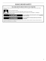
RANGE HOOD SAFETY
Your safety and the safety of others are very important.
We have provided many important safety messages in this manual and on your appliance. Always read and obey all safety
messages.
This is the safety alert symbol.
This symbol alerts you to potential hazards that can kill or hurt you and others.
All safety messages will follow the safety alert symbol and either the word "DANGER" or "WARNING."
These words mean:
You can be killed or seriously injured if you don't immediately
follow instructions.
You can be killed or seriously injured if you don't follow
instructions.
All safety messages will tell you what the potential hazard is, tell you how to reduce the chance of injury, and tell you what can
happen if the instructions are not followed.

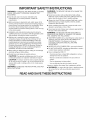
iMPORTANT SAFETY iNSTRUCTiONS
WARNING: TO REDUCE THE RISK OF FIRE, ELECTRIC
SHOCK, OR INJURY TO PERSONS, OBSERVE THE
FOLLOWING:
[] Use this unit only in the manner intended by the
manufacturer. If you have questions, contact the
manufacturer.
[] Before servicing or cleaning the unit, switch power off at
service panel and lock the service disconnecting means to
prevent power from being switched on accidentally. When
the service disconnecting means cannot be locked,
securely fasten a prominent warning device, such as a tag,
to the service panel.
[] Installation work and electrical wiring must be done by
qualified person(s) in accordance with all applicable codes
and standards, including fire-rated construction.
[] Sufficient air is needed for proper combustion and
exhausting of gases through the flue (chimney) of fuel
burning equipment to prevent backdrafting. Follow the
heating equipment manufacturer's guideline and safety
standards such as those published by the National Fire
Protection Association (NFPA), the American Society for
Heating, Refrigeration and Air Conditioning Engineers
(ASHRAE), and the local code authorities.
[] When cutting or drilling into wall or ceiling; do not damage
electrical wiring and other utilities.
[] Ducted fans must always be vented outdoors.
CAUTION: For general ventilating use only. Do not use
to exhaust hazardous or explosive materials and vapors.
CAUTION: To reduce risk of fire and to properly exhaust
air, be sure to duct air outside - do not vent exhaust air into
spaces within walls or ceilings, attics or into crawl spaces,
or garages.
WARNING: TO REDUCE THE RISK OF FIRE, USE ONLY
METAL DUCTWORK.
WARNING: TO REDUCE THE RISK OF A RANGE TOP
GREASE FIRE:
[] Never leave surface units unattended at high settings.
Boilovers cause smoking and greasy spillovers that may
ignite. Heat oils slowly on low or medium settings.
[] Always turn hood ON when cooking at high heat or when
flambeing food (i.e. Crepes Suzette, Cherries Jubilee,
Peppercorn Beef Flamb6).
[] Clean ventilating fans frequently. Grease should not be
allowed to accumulate on fan or filter.
[] Use proper pan size. Always use cookware appropriate for
the size of the surface element.
WARNING: TO REDUCE THE RISK OF INJURY TO
PERSONS IN THE EVENT OF A RANGE TOP GREASE
FIRE, OBSERVE THE FOLLOWING: a
[] SMOTHER FLAMES with a close fitting lid, cookie sheet, or
metal tray, then turn off the burner. BE CAREFUL TO
PREVENT BURNS. If the flames do not go out
immediately, EVACUATE AND CALL THE FIRE
DEPARTMENT.
[] NEVER PICK UP A FLAMING PAN - you may be burned.
[] DO NOT USE WATER, including wet dishcloths or towels -
a violent steam explosion will result.
[] Use an extinguisher ONLY if:
- You know you have a class ABC extinguisher, and you
already know how to operate it.
- The fire is small and contained in the area where it
started.
- The fire department is being called.
- You can fight the fire with your back to an exit.
aBased on "Kitchen Fire Safety Tips" published by NFPA.
[] WARNING: To reduce the risk of fire or electrical shock,
do not use this fan with any solid-state speed control
device.
READ AND SAVE THESE iNSTRUCTiONS

INSTALLATION REQUIREMENTS
_?' i_: _ _._1:_
Gather the required tools and parts before starting installation.
Read and follow the instructions provided with any tools listed
here.
Tools needed
• Level
• Drill
• 11¼'' (3 cm) drill bit
• 3/32"(2.4 mm) drill bit
• 1/8"(3 mm) drill bit
• Pencil
• Wire stripper or utility knife
• Tape measure or ruler
• Pliers
• Caulking gun and weatherproof caulking compound
• Vent clamps
• Jigsaw or keyhole saw
• Flat-blade screwdriver
• Metal snips
• Phillips screwdriver
• Scissors
Parts needed
• Home power supply cable
• 1 - 1/2"(12.7 ram) UL listed or CSA approved strain relief
• 2 UL listed wire connectors
For vented installations, you will also need:
• 1 wall or roof cap
• Metal vent system
For non-vented (recirculating) installations, you will also
need:
• Recirculation Kit Part Number W10271501 for non-vented
(recirculating) installations only. See "Assistance or Service"
section to order.
Parts supplied
Remove parts from packages. Check that all parts are included.
• 2 metal grease filters for 30" (76.2 cm) models
3 metal grease filters for 36" (91.4 cm) models
• 6- flat head screws
• 2 - chimney mounting brackets
• 6 - #10 Phillips head mounting screws
• Upper chimney cover
• Lower chimney cover
• Damper
IMPORTANT: Observe all governing codes and ordinances.
Have a qualified technician install the range hood. It is the
installer's responsibility to comply with installation clearances
specified on the model/serial rating plate. The model/serial rating
plate is located inside the range hood on the rear wall of the
range hood.
Canopy range hood location should be away from strong draft
areas, such as windows, doors and strong heating vents.
Cabinet opening dimensions that are shown must be used. Given
dimensions provide minimum clearance.
Grounded electrical outlet is required. See "Electrical
Requirements" section.
The canopy range hood is factory set for venting through the roof
or through the wall. For non-vented (recirculating) Installation see
"Non-vented (recirculating) Installations" in "Prepare Location"
section. Recirculation Kit Part Number W10271501 is available
from your dealer or an authorized parts distributor.
All openings in ceiling and wall where canopy range hood will be
installed must be sealed.
For Mobile Home Installations
The installation of this range hood must conform to the
Manufactured Home Construction Safety Standards, Title 24
CFR, Part 328 (formerly the Federal Standard for Mobile Home
Construction and Safety, Title 24, HUD, Part 280) or when such
standard is not applicable, the standard for Manufactured Home
Installation 1982 (Manufactured Home Sites, Communities and
Setups) ANSI A225.1/NFPA 501A*, or latest edition, or with local
codes.
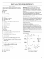
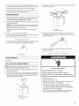
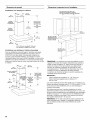
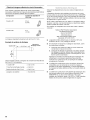
Product Dimensions
Vented Installations
10W' J
(26.0 cm)
Upper
chimney
Lower
chimney
(30.0 crn)
25%" (65.1 crn)
rnin.
371A" (94.6 crn)
max.
21W' overall chimney
(54.0 cm) height
30" (76.2 crn) model: 29_%d'(76.0crn)
36" (91.4 crn) model: 35s/8"(89.9crn)

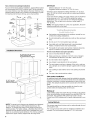
Non-vented (recirculating) Installations
For non-vented (recirculating) installations, optional Recirculation
Kit Part Number W10271501, must be used. This kit includes a
new lower chimney cover that replaces the lower chimney cover
shipped with the range hood, a diverter with extensions, 2 grids
for inserting into the lower chimney, and a charcoal filter.
(30.0 cm)
10W'
(26.0 cm) ..........................................
u
chimney
39/16"
(9.1 cm)
125/8"
(32.0 cm)
25%"(65.1 cm)
rain.
371A" (94.6 cm)
max.
overall chimney
height
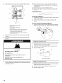
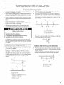
Installation Dimensions
18" (45.7 cm) rain.
clearance upper --
cabinet to countertop
30" (76.2 cm) or 36" (91.4 cm)
cabinet opening width
if installed between cabinets)
i
See Note*
IM PORTANT:
Minimum distance "X": 30" (76.2 cm)
Suggested maximum distance "X": 36" (91.4 cm)
Chimneys can be adjusted for ceilings between 8' 3/8"(2.55 m)
and 9' 6" (2.90 m) in both vented and non-vented (recirculating)
applications.
If you have shorter ceilings, the upper chimney can be shortened
by removing up to 51¼'' (13.3 cm) off the bottom for vented
applications and 111¼"(28.6 cm) for non-vented (recirculating)
applications. This will give you a minimum ceiling height of
7' 8" (2.34 m).
NOTE: If the upper chimney is cut for your application, the lower
chimney bracket will not be used.
• Vent system must terminate to the outdoors, except for non-
vented (recirculating) installations.
• Do not terminate the vent system in an attic or other enclosed
area.
• Do not use 4" (10.2 cm) laundry-type wall caps.
• Use metal vent only. Rigid metal vent is recommended.
Plastic or metal foil vent is not recommended.
• The length of vent system and number of elbows should be
kept to a minimum to provide efficient performance.
For the most efficient and quiet operation:
• Use no more than three 90° elbows.
• Make sure there is a minimum of 24" (61.0 cm) of straight
vent between the elbows if more than 1 elbow is used.
• Do not install 2 elbows together.
• Use clamps to seal all joints in the vent system.
• The vent system must have a damper. If the roof or wall cap
has a damper, do not use the damper supplied with the range
hood.
• Use caulking to seal exterior wall or roof opening around the
cap.
• The size of the vent should be uniform.
Cold weather installations
An additional back draft damper should be installed to minimize
backward cold air flow and a thermal break should be installed to
minimize conduction of outside temperatures as part of the vent
system. The damper should be on the cold air side of the thermal
break.
The break should be as close as possible to where the vent
system enters the heated portion of the house.
36" (91.4 cm)
countertop height
*NOTE: The range hood chimneys are adjustable and designed
to meet varying ceiling or soffit heights depending on the
distance "X" between the bottom of the range hood and the
cooking surface. For higher ceilings, a Stainless Steel Chimney
Extension Kit Part Number W10271503 is available from your
dealer or an authorized parts distributor. The chimney extension
replaces the upper chimney shipped with the range hood.
Makeup air
Local building codes may require the use of make up air systems
when using ventilation systems greater than specified CFM of air
movement. The specified CFM varies from locale to locale.
Consult your HVAC professional for specific requirements in your
area.
Venting Methods
This canopy range hood is factory set for venting through the roof
or through the wall.
A 6" (15.2 cm) round vent system is needed for installation (not
included). The hood exhaust opening is 6" (15.2 cm) round.
6

NOTE: Flexible vent is not recommended. Flexible vent creates
back pressure and air turbulence that greatly reduce
performance.
Vent system can terminate either through the roof or wall. To vent
through a wall, a 90° elbow is needed.
Rear discharge
A 90° elbow may be installed immediately above the hood.
For non-vented (recirculating) installations
If it is not possible to vent cooking fumes and vapors to the
outside, the hood can be used in the non-vented (recirculating)
version, fitting an activated carbon filter and the diverter. Fumes
and vapors are recycled through the top grille.
NOTE: Non-vented (recirculating) installation is not allowed over
cooktops with BTU ratings of 60,000 or higher.
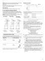
Roof Venting Wall Venting Non-vented
(recirculating)
"A
Bj;
A. Roof cap A. Wall cap A. Diverter
B. 6" (15.2 cm) B. 6" (15.2 cm) B. 6" (15.2 cm)
round vent round vent round vent
extension
Calculating Vent System Length
To calculate the length of the system you need, add the
equivalent feet (meters) for each vent piece used in the system.
Vent Piece 6" (15.2 cm) Round
45° elbow 2.5 ft
(0.8m)
90° elbow 5.0 ft
(1.5m)
Maximum equivalent vent length is 35 ft (10.7 m).
Example vent system
.ooo,bow 8 ......w°,,c°p
The following example falls within the maximum recommended
vent length of 35 ft (10.7 m).
1 - 90 ° elbow = 5.0 ft (1.5 m)
1 - wall cap = 0.0 ft (0.0 m)
8 ft (2.4 m) straight = 8.0 ft (2.4 m)
Length of system = 13.0 ft (3.9 m)
Observe all governing codes and ordinances.
Ensure that the electrical installation is adequate and in
conformance with National Electrical Code, ANSI/NFPA 70 (latest
edition), or CSA Standards C22.1-94, Canadian Electrical Code,
Part 1 and C22.2 No. 0-M91 (latest edition) and all local codes
and ordinances.
If codes permit and a separate ground wire is used, it is
recommended that a qualified electrician determine that the
ground path is adequate.
A copy of the above code standards can be obtained from:
National Fire Protection Association
One Batterymarch Park
Quincy, MA 02269
CSA International
8501 East Pleasant Valley Road
Cleveland, OH 44131-5575
• A 120 Volt, 60 Hz., AC only, 15-amp, fused electrical circuit is
required.
• If the house has aluminum wiring follow the procedure below:
1. Connect a section of solid copper wire to the pigtail
leads.
2. Connect the aluminum wiring to the added section of
copper wire using special connectors and/or tools
designed and UL listed for joining copper to aluminum.
Follow the electrical connector manufacturer's recommended
procedure. Aluminum/copper connection must conform with
local codes and industry accepted wiring practices.
• Wire sizes and connections must conform with the rating of
the appliance as specified on the model/serial rating plate.
The model/serial plate is located behind the filter on the rear
wall of the range hood.
• Wire sizes must conform to the requirements of the National
Electrical Code, ANSI/NFPA 70 (latest edition), or CSA
Standards C22.1-94, Canadian Electrical Code, Part 1 and
C22.2 No. 0-M91 (latest edition) and all local codes and
ordinances.

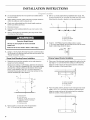
INSTALLATION INSTRUCTIONS
• It is recommended that the vent system be installed before
hood is installed.
• Before making cutouts, make sure there is proper clearance
within the ceiling or wall for exhaust vent.
• Check your ceiling height and the hood height maximum
before you select your hood.
1. Disconnect power.
2. Determine which venting method to use: roof, wall, or non-
vented.
3. Select a flat surface for assembling the range hood. Place
covering over that surface.
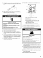
Excessive Weight Hazard
Use two or more people to move and install
range hood.
Failure to do so can result in back or other injury.
4. Using 2 or more people, lift range hood onto covered surface.
Tip the hood on its back and remove filters and set aside. See
"Range Hood Care" section.
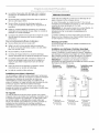
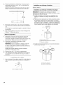
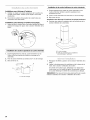
Range Hood Mounting Screws Installation
1.
2.
Determine and mark the centerline on the wall where the
range hood will be installed.
Based on the ceiling or soffit height, determine the distance
"X" (30" [76.2 cm] min, suggested 36" [91.4 cm] max) needed
between the cooking surface and the bottom of the range
hood. To this distance, add 151/8"(43.8 cm) and draw a
horizontal line (A) about 24" (61.0 cm) long centered on the
vertical centerline (B) at this distance.
I
A
\l
I
1
I
I
I
t
DI c
\
!
I
A. Horizontal fine
B. 15_" (43.8 cm)
C. Distance "X" (30" [76.2 cm] min,
suggested 36" [91.4 cm] max)
D. Vertical centerline
E. Cooking surface
Mark 2 points on each side of the horizontal line
49/16'' (11.6 cm) from the vertical centerline.
3.
Drill 3/32"(2.4 mm) pilot holes for installation into wood. The
screws provided are for mounting the range hood into wood.
Mounting into drywall or plaster is not recommended.
A
B
I I
............. /,
C
A. Horizontal fine
B. Vertical centerline
C. 4 _" (11.6 cm)
4. Install 2 - #10 Phillips head mounting screws. Leave a
1/4"(6.4 mm) gap between the wall and the back of the screw
head to slide range hood into place.
(6.4 ram) _
Chimney Support Bracket Installation
1.
Place one of the chimney brackets against the wall so that its
top edge is 1/16"(2.0 mm) from the ceiling or soffit and level.
Align the center notches of the bracket and the centerline.
Mark the centers of the bracket holes.
O
o f
B
2.
A. Vertical centerline
B. Center notches
C. _" (1.6 mm)
Place the other chimney bracket on the wall so that its lower
edge is 163/16'' (41.1 cm) from the ceiling or soffit and level.
Align the center notches of the bracket and the centerline.
Mark the centers of the bracket holes.
I O
V
i
°T
16¾0"
(41.1 cm)
el
8

3. Drill 3/32"(2.4 mm) pilot holes for installation into wood. The
screws provided are for mounting the range hood into wood.
Mounting into drywall or plaster is not recommended.
4. Attach each bracket to the wall with 2 - #10 Phillips head
mounting screws. Tighten screws securely.
Complete Preparation
1.
2=
Determine and make all necessary cuts in the wall for the vent
system. Install the vent system before installing the range
hood. See the "Venting Requirements" section.
Determine the location where the power supply cable will be
run through the wall.
NOTE: For wiring flexibility, the terminal box is external to the
range hood motor. About 24" (61.0 cm) of wire connects the
terminal box to the range hood motor.
Check that the lower chimney cover will hide the selected
location.
3. Drill a 1V4"(3.2 cm) hole at this location.
4. Pull enough power supply cable through the wall to allow for
easy connection to the terminal box.
_j ....
1. Use a flat-blade screwdriver and tighten the 2 leveling screws
located close to the range hood mounting brackets.
A.Leveling screw
Vented Installations
Go to Step 5.
Non-vented (recirculating) Installations
NOTE: Non-vented (recirculating) installation is not allowed over
cooktops with BTU ratings of 60,000 or higher.
2. Install the non-vented (recirculating) conversion kit ordered
for your range hood.
3. Fit the diverter over the vent motor exhaust and push down to
seat. Check that the diverter exhaust outlets are parallel with
the vent motor sides so that they align with the vent cover
openings in the lower chimney.
A ..........................................E_
C ................
A. Diverter
B. Vent motor exhaust
C. Vent motor
4.
Install the 2 vent extension pieces onto the diverter pushing
them until they stop.
A
5.
A. Diverter
B. Exhaust extension
Using 2 or more people, lift the range hood and place the
mounting hood brackets over the mounting screws. Securely
tighten the screws.
6. Level the range hood. Adjust the 2 leveling screws (see
Step 1) as needed.
Electrical Shock Hazard
Disconnect power before servicing.
Replace all parts and panels before operating.
Failure to do so can result in death or electrical shock.
1. Disconnect power.
2. Remove terminal box cover.
3. Remove the knockout in the terminal box and install a UL
listed or CSA approved V2"strain relief.
4. Center the wiring hole in the terminal box over the
11¼'' (3.2 cm) diameter wiring hole in the wall. Mark the
2 terminal box mounting holes. Drill V8"(3.0 mm) diameter
holes as needed for your installation.
5. Run 3 wires, black, white and green (or bare), from home
power supply through strain relief into terminal box.

6=
Attach terminal box to the wall and securely tighten screws.
C
..............E
......J G
D
A. Home power supply cable
B. Black wires
C. UL listed wire connectors
D. White wires
E. Green (or bare) ground wire from home power
supply connected to green ground screw
F. Range hood power supply cable
G. Range hood power supply cable connected to
green ground screw
7. Use UL listed wire connectors and connect black wires (B)
together.
8. Use UL listed wire connectors and connect white wires (D)
together.
Fire Hazard
Electrically ground the blower.
Use copper wire.
Connect ground wire to green ground screw in
terminal box.
Failure to do so can result in death, fire, or
electrical shock.
9. Connect green (or bare) ground wire from home power supply
to the unused green ground screw (E)in the terminal box and
tighten ground screw.
10. Push excess home power supply cable back through the
strain relief and tighten strain relief screws. Use caulking to
seal openings.
11. Install terminal box cover and tighten screws.
12. Check all light bulbs to make sure they are secure in their
sockets.
13. Reconnect power.
J
For Vented Installations
1. Install damper on top of the exhaust opening. Check that the
damper opens freely.
2. Connect the vent system and seal all connections with
clamps.
For Non-vented (recirculating) Installations
1. Insert the charcoal filter into the opening behind the grease
filters and lock into place. See "Range Hood Care" section.
Install Upper Chimney Cover
1. Slightly spread the sides of the cover apart and hook them
behind the chimney mounting brackets.
2. Attach the cover to the brackets with 4 mounting screws.
3. Securely tighten screws.
A
A. 4 mounting screws
Install Lower Chimney Cover
1. Slightly spread the sides of the cover apart and hook them
behind the upper chimney and the wall.
2. Attach the cover to the hood with 2 mounting screws.
3. Securely tighten screws.
10

For non-vented (recirculating) installations only
4. Snap vent grids into openings in lower chimney.
A
1. Replace grease filters. See the "Range Hood Care" section.
2. Check the operation of the range hood fan and light. See
"Range Hood Use" section.
If range hood does not operate, check to see whether a
circuit breaker has tripped or a household fuse has blown.
Disconnect power and check wiring connections.
NOTE: To get the most efficient use from your new range hood,
read the "Range Hood Use" section.
A. 2 mounting screws
B. Vent grids (for non-vented installations)
RANGE HOOD USE
The range hood is designed to remove smoke, cooking vapors
and odors from the cooktop area. For best results, start the hood
before cooking and allow it to operate several minutes after the
cooking is complete to clear all smoke and odors from the
kitchen.
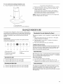
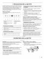
Control Panel
The range hood controls are located on the right-hand front
surface of the range hood.
®
®®
E FA B C D G
Operating the Fan and Adjusting Fan Speed
The fan has 4 speeds: 1 (low), 2 (medium), 3 (medium-high), and
4 (high).
1. Press the On/Off button (A) to turn the fan on. The speed
setting will appear in the display.
2. Press the "plus" (+) or "minus" (-) buttons to increase or
decrease the fan speed.
3. Press the On/Off button (A) to turn off the fan.
10-Minute Boost Function
Press the "H" button to start the 10-minute boost function. The
fan motor will run on its highest speed (4) as the display counts
down from 10 minutes. At the end of 10 minutes, the fan will
return to the previously selected speed.
A. Fan motor on/off
B. Decrease fan motor speed
C. Increase fan motor speed
D. Electronic display
E. 10 minute timed boost
E Light
G. Night light
Operating the Light
1. Press the light button (F) to turn on the light.
2. Press the light button (F) to turn off the light.
Operating the Night Light
1. Press the night light button (G) to turn on the night light.
2. Press the night light button (G) to turn off the night light.
Reset Filter Alert
After 100 hours of use, "C" will appear in the range hood display.
This "C" indicates that the filter must be cleaned. "C" will appear
only when turning off the range hood fan.
Reset Alarm Display
1. Turn off the range hood fan and light.
2. Press the "plus" (+) button for 4 seconds. The "C" will
disappear from the display, and the counter will reset to "0."
Thermal Protector
The range hood is equipped with a thermal protector to avoid
overheating conditions. If the range hood shuts off while in use,
press the on/off button to turn off the range hood. Wait
approximately 60 minutes, then press the on/off button to restart
the range hood.
11

RANGE HOOD CARE
IMPORTANT: Clean the hood and grease filters frequently
according to the following instructions. Replace grease filters
before operating hood.
Be sure lights are cool before cleaning the hood.
Exterior Surfaces
Clean the range hood with a mild detergent and soft cloth. To
avoid damage to the exterior surface, do not use abrasive
cleanser or steel-wool pads.
Metal Grease Filters
The filters should be washed frequently. Place metal filters in
dishwasher or hot detergent solution to clean.
Drain water and let each filter dry thoroughly before replacing it.
To Remove Metal Grease Filters
1. Turn off fan and lights. Check that halogen lamp is cool.
2. Pull out on knob and turn counterclockwise to release metal
grease filters.
To Replace Metal Grease Filters
1. Insert back edge of filter into rear channel of the filter
opening.
2. Pull out on knob and turn counterclockwise. Position front
edge into place and release knob.
Charcoal Filters - For Non-Vented (recirculating)
Installations
The charcoal filter is not washable nor reusable.
It should be changed every 4 months in normal use or more
frequently in heavy use. To order new charcoal filters see
"Assistance or Service" section.
The charcoal filter captures unpleasant cooking odors.
To Install Charcoal Filters
1. Turn fan and lights off. Check that halogen lamp is cool.
2. Remove the metal grease filters. See "Metal Grease Filters"
section.
3. Set metal grease filters aside.
4=
5=
Place charcoal filter into opening. Press back and up on fixing
hooks to secure filter in place.
Replace metal grease filters. See "Metal Grease Filters"
section.
To Replace Charcoal Filters
1. Turn fan and lights off. Check that halogen lamp is cool.
2. Remove the metal grease filters. See "Metal Grease Filters"
section.
3. Set metal grease filters aside.
4. Discard the used charcoal filter.
5. Place charcoal filter into opening. Press back and up on fixing
hooks to secure filter in place.
6. Replace metal grease filters. See "Metal Grease Filters"
section.
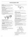
Replacing a Halogen Lamp
Turn off the range hood and allow the halogen lamp to cool. To
avoid damage or decreasing the life of the new bulb, do not
touch bulb with bare fingers. Replace bulb, using tissue or
wearing cotton gloves to handle bulb.
If new lamps do not operate, make sure the lamps are inserted
correctly before calling service.
1. Disconnect power.
2. Use a Phillips screwdriver and remove the retainer clips
located at each end of the lamp panel.
3. Slide the lamp panel all the way to the right. Lower the left
end of the panel below the support tabs.
4. Remove the panel by sliding it back to the left. Set panel
aside.
A B .......
......... ........................C
...... D
A. Halogen lamp C. Screw
B. Support tabs D. Retainer clip
5. Gently push the lamp out of its socket clips.
6. Insert a new 12-volt, 20-watt halogen lamp into the socket
and push into the clips.
7. Replace the lamp panel and retainer clips. Tighten clip
screws securely.
8. Reconnect power.
12

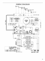
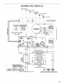
WIRING DIAGRAM
CONNECTIONS
TO
TERMINALS
2-4
3-4
0-1 MOT.
O TO DECREASE SPEED
TO INCREASE SPEED
--DIS_)YIo MINUTE INTENSIVE SPEED
0-1 LIGHT
1 @0-1 NIGHTLIGHT,
[] [] [_ [] B [] [] [] O] PUSH BUTTON PANEL
]
OHM RESISTANCE
BETWEEN TERMINALS (_"_)
{SEE CONNECTIONS)
15.8±1.1
11.0±0.8
5.74-0.4.
TO RANGE HOOD CASE_
TO THE COVER BOX
Y-GN
m
!
Y-GN
2 LAMPS
3 LAMPS
a
ox
oo
.t.-m
u..it_
oz
z_
Z
>-
m
l
NO LOAD TOROIDAL
TRANSFORMER OHM (£J)
RESISTANCE
W-R BK-BK
15.204-0.76 ).255-F0.025
12JO-FO.73 0.180+0.018
BU
GY
W
Y
BR II ]
II
20 luF 240V
y-
LINE IN 120 Vac 60 Hz
BR
V
R
SIDE INSERT CABLES
"[
TOROIDAL TRANSFORMER
n"
,,€t'
DIRECTIONAL LAMPS
LU
--I
m
o
LU
U'J
LU
Q
13

ASSISTANCE OR SERVICE
When calling for assistance or service, please know the purchase
date and the complete model and serial number of your
appliance. This information will help us to better respond to your
request.
If you need replacement parts
If you need to order replacement parts, we recommend that you
use only factory specified parts. Factory specified parts will fit
right and work right because they are made with the same
precision used to build every new appliance. To locate factory
specified replacement parts in your area, call us or your nearest
designated service center.
Call the KitchenAid Customer eXperience Center toll free:
1-800-422-1230.
Our consultants provide assistance with:
• Features and specifications on our full line of appliances.
• Installation information.
• Use and maintenance procedures.
• Accessory and repair parts sales.
• Specialized customer assistance (Spanish speaking, hearing
impaired, limited vision, etc.).
• Referrals to local dealers, repair parts distributors and service
companies. KitchenAid designated service technicians are
trained to fulfill the product warranty and provide after-
warranty service, anywhere in the United States.
To locate the KitchenAid designated service company in your
area, you can also look in your telephone directory Yellow
Pages.
For further assistance
If you need further assistance, you can write to KitchenAid with
any questions or concerns at:
KitchenAid Brand Home Appliances
Customer eXperience Center
553 Benson Road
Benton Harbor, MI 49022-2692
Call the KitchenAid Canada Customer eXperience Centre toll
free: 1-800-807-6777.
Our consultants provide assistance with:
• Features and specifications on our full line of appliances.
• Use and maintenance procedures.
• Accessory and repair parts sales.
• Referrals to local dealers, repair parts distributors and service
companies. KitchenAid Canada designated service
technicians are trained to fulfill the product warranty and
provide after-warranty service, anywhere in Canada.
For further assistance
If you need further assistance, you can write to KitchenAid
Canada with any questions or concerns at:
Customer eXperience Centre
KitchenAid Canada
1901 Minnesota Court
Mississauga, Ontario L5N 3A7
Please include a daytime phone number in your correspondence.
Charcoal Filter Kit
(for non-vented installations only)
Order Part Number 8285507
Recirculation Kit
(for non-vented installations only)
Order Part Number W10271501
Chimney Extension Kit
Order Part Number W10271503 Stainless Steel
Please include a daytime phone number in your correspondence.
14

KITCHENAID ®VENTILATION WARRANTY
LIMITED WARRANTY
For one year from the date of purchase, when this major appliance is operated and maintained according to instructions attached to or
furnished with the product, KitchenAid brand of Whirlpool Corporation or Whirlpool Canada LP (hereafter "KitchenAid") will pay for
Factory Specified Parts and repair labor to correct defects in materials or workmanship. Service must be provided by a KitchenAid
designated service company. This limited warranty is valid only in the United States or Canada and applies only when the major
appliance is used in the country in which it was purchased. Outside the 50 United States and Canada, this limited warranty does not
apply. Proof of original purchase date is required to obtain service under this limited warranty.
ITEMS EXCLUDED FROM WARRANTY
This limited warranty does not cover:
1. Service calls to correct the installation of your major appliance, to instruct you on how to use your major appliance, to replace or
repair house fuses, or to correct house wiring or plumbing.
2. Service calls to repair or replace appliance light bulbs, air filters or water filters. Consumable parts are excluded from warranty
coverage.
3. Repairs when your major appliance is used for other than normal, single-family household use or when it is used in a manner that is
contrary to published user or operator instructions and/or installation instructions.
4. Damage resulting from accident, alteration, misuse, abuse, fire, flood, acts of God, improper installation, installation not in
accordance with electrical or plumbing codes, or use of consumables or cleaning products not approved by KitchenAid.
5. Cosmetic damage, including scratches, dents, chips or other damage to the finish of your major appliance, unless such damage
results from defects in materials or workmanship and is reported to KitchenAid within 30 days from the date of purchase.
6. Costs associated with the removal from your home of your major appliance for repairs. This major appliance is designed to be
repaired in the home and only in-home service is covered by this warranty.
7. Repairs to parts or systems resulting from unauthorized modifications made to the appliance.
8. Expenses for travel and transportation for product service if your major appliance is located in a remote area where service by an
authorized KitchenAid servicer is not available.
9. The removal and reinstallation of your major appliance if it is installed in an inaccessible location or is not installed in accordance
with published installation instructions.
10. Major appliances with original model/serial numbers that have been removed, altered or cannot be easily determined. This warranty
is void if the factory applied serial number has been altered or removed from your major appliance.
The cost of repair or replacement under these excluded circumstances shall be borne by the customer.
DISCLAIMER OF IMPLIED WARRANTIES; LIMITATION OF REMEDIES
CUSTOMER'S SOLE AND EXCLUSIVE REMEDY UNDER THIS LIMITED WARRANTY SHALL BE PRODUCT REPAIR AS PROVIDED
HEREIN. IMPLIED WARRANTIES, INCLUDING WARRANTIES OF MERCHANTABILITY OR FITNESS FOR A PARTICULAR PURPOSE,
ARE LIMITED TO ONE YEAR OR THE SHORTEST PERIOD ALLOWED BY LAW. KITCHENAID SHALL NOT BE LIABLE FOR
INCIDENTAL OR CONSEQUENTIAL DAMAGES. SOME STATES AND PROVINCES DO NOT ALLOW THE EXCLUSION OR LIMITATION
OF INCIDENTAL OR CONSEQUENTIAL DAMAGES, OR LIMITATIONS ON THE DURATION OF IMPLIED WARRANTIES OF
MERCHANTABILITY OR FITNESS, SO THESE EXCLUSIONS OR LIMITATIONS MAY NOT APPLY TO YOU. THIS WARRANTY GIVES
YOU SPECIFIC LEGAL RIGHTS, AND YOU MAY ALSO HAVE OTHER RIGHTS WHICH VARY FROM STATE TO STATE OR PROVINCE
TO PROVINCE.
If outside the 50 United States and Canada, contact your authorized KitchenAid dealer to determine if another warranty applies.
If you need service, first see the "Troubleshooting" section of the Use & Care Guide. After checking "Troubleshooting," you may find
additional help by checking the "Assistance or Service" section or by calling KitchenAid. In the U.S.A., call 1-800-422-1230. In Canada,
call 1-800-807-6777. 9/07
Keep this book and your sales slip together for future
reference. You must provide proof of purchase or installation
date for in-warranty service.
Write down the following information about your major appliance
to better help you obtain assistance or service if you ever need it.
You will need to know your complete model number and serial
number. You can find this information on the model and serial
number label located on the product.
Dealer name
Address
Phone number
Model number
Serial number
Purchase Date
15

16

p p
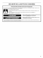
SECURITE DE LA HOTIT DE CUISINIERE
Votre securit6 et celle des autres est tres importante.
Nous donnons de nombreux messages de s6curit6 importants dans ce manuel et sur votre appareil m6nager. Assurez-vous de
toujours lire tousles messages de s6curit6 et de vous y conformer.
Voici le symbole d'alerte de s6curit&
Ce symbole d'alerte de s6curit6 vous signale les dangers potentiels de d6c6s et de blessures graves &vous
et & d'autres.
Tous les messages de s6curit6 suivront le symbole d'alerte de s6curit6 et le mot "DANGER" ou
"AVERTISSEMENT". Ces mots signifient •
Risque possible de d6ces ou de blessure grave si vous ne
suivez pas imm6diatement les instructions.
Risque possible de d6cbs ou de blessure grave si vous
ne suivez pas les instructions.
Tous les messages de s6curit6 vous diront quel est le danger potentiel et vous disent comment r6duire le risque de blessure et
ce qui peut se produire en cas de non-respect des instructions.
17

llVIPORTANTES iNSTRUCTiONS DE SI CURITI
AVERTISSEIVIENT : POUR REDUIRE LE RISQUE
D'INCENDIE, CHOC ¢:LECTRIQUE OU DOMMAGES
CORPORELS, RESPECTER LES INSTRUCTIONS
SUIVANTES :
m Utiliser cet appareil uniquement dans les applications
envisag6es par le fabricant. Pour toute question, contacter
le fabricant.
m Avant d'entreprendre un travail d'entretien ou de nettoyage,
interrompre I'alimentation de la hotte au niveau du tableau
de disjoncteurs, et verrouiller le tableau de disjoncteurs
pour emp6cher tout r@ablissement accidentel de
I'alimentation du circuit. Lorsqu'il n'est pas possible de
verrouiller le tableau de disjoncteurs, placer sur le tableau
de disjoncteurs une @iquette d'avertissement pro6minente
interdisant le r@ablissement de I'alimentation.
m Tout travail d'installation ou c&blage 61ectrique doit 6tre
r6alis6 par une personne qualifi6e, dans le respect des
prescriptions de tousles codes et normes applicables, y
compris les codes du b&timent et de protection contre les
incendies.
m Une source d'air de d6bit suffisant est n6cessaire pour le
fonctionnement correct de tout appareil & gaz (combustion
et 6vacuation des gaz & combustion par la chemin6e), pour
qu'il n'y ait pas de reflux des gaz de combustion. Respecter
les directives du fabricant de 1'6quipement de chauffage et
les prescriptions des normes de s6curit6 - comme celles
publi6es par la National Fire Protection Association (NFPA)
et I'American Society for Heating, Refrigeration and Air
Conditioning Engineers (ASHRAE), et les prescriptions des
autorit6s r6glementaires locales.
m Lors d'op@ations de d6coupage et de perqage dans un mur
ou un plafond, veiller & ne pas endommager les c&blages
61ectriques ou canalisations qui peuvent s'y trouver.
m Les ventilateurs d'6vacuation doivent toujours d6charger
I'air & I'ext@ieur.
IVilSE EN GARDE : Cet appareil est con_:u uniquement
pour la ventilation g6n@ale. Ne pas I'utiliser pour I'extraction
de mati_res ou vapeurs dangereuses ou explosives.
MISE EN GARDE : Pour minimiser le risque d'incendie
et 6vacuer ad6quatement les gaz, veiller &acheminer I'air
aspir6 par un conduit jusqu'b, I'ext@ieur - ne pas d6charger
I'air aspir6 dans un espace vide du b&timent comme une
cavit6 murale, un plafond, un grenier, un vide sanitaire ou
un garage.
AVERTISSEMENT : POUR R¢:DUIRE LE RISQUE
D'INCENDIE, UTILISER UNIQUEMENT DES CONDUITS
MI2TALLIQUES.
AVERTISSEIVIENT : POUR MINIMISER LE RISQUE
D'UN FEU DE GRAISSE SUR LA CUISINIF:RE :
[] Ne jamais laisser un 616ment de surface fonctionner &
puissance de chauffage maximale sans surveillance. Un
renversement/d6bordement de mati_re graisseuse pourrait
provoquer une inflammation et la g6n@ation de fum6e.
Utiliser une puissance de chauffage moyenne ou basse
pour le chauffage d'huile.
[] Veiller & toujours faire fonctionner le ventilateur de la hotte
Iors de la cuisson avec une puissance de chauffage 61ev6e
ou Iors de la cuisson d'un mets &flamber (& savoir cr6pes
Suzette, cerise jubil6e, steak au poivre flamb6).
[] Nettoyer fr6quemment les ventilateurs d'extraction. Veiller &
ne pas laisser la graisse s'accumuler sur les surfaces du
ventilateur ou des filtres.
[] Utiliser toujours un ustensile de taille appropri6e. Utiliser
toujours un ustensile adapt6 & la taille de 1'616ment
chauffant.
AVERTISSEMENT : POUR RE_DUIRE LE RISQUE DE
DOMMAGES CORPORELS APRF:S LE DECLENCHEMENT
D'UN FEU DE GRAISSE SUR LA CUISINI_:RE, APPLIQUER
LES RECOMMANDATIONS SUIVANTES :a
[] Placer sur le r6cipient un couvercle bien ajust6, une t61e &
biscuits ou un plateau m6tallique POUR ETOUFFER LES
FLAMMES, puis 6teindre le brt_leur. VEILLER ,&.¢:VITER
LES BRULURES. Si les flammes ne s'@eignent pas
imm6diatement, ¢:VACUER LA PIECE ET APPELER LES
POMPIERS.
[] NE JAMAIS PRENDRE EN MAIN UN RECIPIENT
ENFLAMME - vous risquez de vous brQler.
[] NE PAS UTILISER D'EAU, ni un torchon humide - ceci
pourrait provoquer une explosion de vapeur brQlante.
[] Utiliser un extincteur SEULEMENT si:
- IIs'agit d'un extincteur de classe ABC, dont on connaft le
fonctionnement.
- IIs'agit d'un petit feu encore limit6 & I'endroit oQ il s'est
d6clar&
- Les pompiers ont 6t6 contact6s.
- II est possible de garder le dos orient6 vers une sortie
pendant I'op@ation de lutte contre le feu.
aRecommandations tir6es des conseils de s6curit6 en cas
d'incendie de cuisine publi6s par la NFPA.
[] AVERTISSEMENT : Pour r6duire le risque d'incendie
ou de choc 61ectrique, ne pas utiliser ce ventilateur avec un
quelconque dispositif de r6glage de la vitesse & semi-
conducteurs.
LIRE ET CONSERVER CES INSTRUCTIONS
18

EXIGENCES D'INSTALLATION
Rassembler les outils et pieces necessaires avant de commencer
I'installation. Lire et suivre les instructions fournies avec les outils
indiqu6s ici.
Outils n_cessaires
• Niveau
• Perceuse
• Foret de 11¼"(3 cm)
• Foret de 3/32"(2,4 mm)
• Foret de 1/8"(3,0 mm)
• Crayon
• Pince & denuder ou couteau utilitaire
• Metre-ruban ou regle
• Pince
• Pistolet & calfeutrage et compose de calfeutrage resistant
aux intemperies
• Brides de serrage pour conduit d'evacuation
• Scie sauteuse ou scie &guichet
• Tournevis & lame plate
• Cisaille de ferblantier
• Tournevis Phillips
• Ciseaux
Pi6ces n6cessaires
• C&ble d'alimentation electrique du domicile
• 1 serre-c&ble de V2"(12,7 mm) (homologation UL ou CSA)
• 2 connecteurs de ills homologues UL
Pour les installations avec d_charge a I'ext_rieur, il vous
faudra aussi :
• 1 bouche de decharge (decharge a travers le mur ou & travers
le toit)
• Conduit d'evacuation metallique
Pour les installations sans d_charge a I'ext_rieur (recyclage),
il vous faudra aussi :
• Ensemble de cheminee pour recyclage, piece n° W10271501,
pour les installations sans decharge & I'exterieur seulement.
Voir la section "Assistance ou service" pour commander.
Pi_ces fournies
Retirer les pieces des emballages. Verifier que toutes les pieces
sont presentes.
• 2 filtres &graisse metalliques, pour modele de 30" (76,2 cm)
3 filtres & graisse metalliques, pour modele de 36" (91,4 cm)
• 6 vis a tete plate
• 2 brides de montage de la cheminee
• 6 vis de montage a tete Phillips n° 10
• Cache-cheminee, partie superieure
• Cache-cheminee, partie inferieure
• Clapet
IMPORTANT : Observer les dispositions de tous les codes et
reglements en vigueur.
Confier I'installation de la hotte &un technicien qualifi& C'est &
I'installateur qu'incombe la responsabilite de respecter les
distances de separation specifiees sur la plaque signaletique de
I'appareil. La plaque signaletique est situee a I'interieur de la
hotte, sur la paroi arriere.
On doit toujours installer la hotte a distance des sources de
courant d'air (fenetres, portes et bouches de chauffage).
Respecter les dimensions indiquees pour les ouvertures
decouper dans les placards; ces dimensions tiennent compte
des valeurs minimales des degagements de separation.
On doit disposer d'une prise de courant electrique reliee a la
terre. Voir la section "Specifications electriques".
La hotte est configuree a I'usine pour la decharge a travers le toit
ou un tour. Pour une installation sans decharge a I'exterieur
(recyclage), voir "Installation sans decharge a I'exterieur
(recyclage)", & la section "Preparation de I'emplacement".
L'ensemble de cheminee pour recyclage (piece n° W10271501)
est disponible chez votre marchand ou chez un distributeur de
pieces autoris&
Assurer I'etancheite au niveau de chaque ouverture decoupee
dans le plafond ou le tour pour I'installation de la hotte de
cuisinlere.
Installation dans une r_sidence mobile
L'installation de cette hotte doit satisfaire aux exigences de la
norme Manufactured Home Construction Safety Standards, Titre
24 CFR, partie 328 (anciennement Federal Standard for Mobile
Home Construction and Safety, titre 24, HUD, partie 280); Iorsque
cette norme n'est pas applicable, I'installation doit satisfaire aux
criteres de la plus recente edition de la norme Manufactured
Home Installation 1982 (Manufactured Home Sites, Communities
and Setups)ANSI A225.1/NFPA 501A*, ou des codes et
reglements Iocaux.
19

Dimensions du produit Dimensions _ respecter Iors de I'installation
Installations avec d_charge a I'ext_rieur
10W'
(26,0 crn)
Section
superieure
de chemin_e
Section
inf_rieure
de chemin_e
(30,0 crn)
.............. _ dehauteurchemin_etotale:
25%" (65,1 cm)
rain.
211A" 371A" (94,6 cm)
(54,0 crn) max.
(12,1 cm)
291%6"(76,0 crn) : mod_Ne 30" (76,2 cm)
35%"(89,9 crn) : rnodeNe 36" (91,4 crn)
Installations sans d_charge a I'ext_rieur (recyclage)
Pour les installations sans decharge a I'exterieur (recyclage),
I'ensemble de cheminee facultatif pour recyclage, piece n°
W10271501, dolt _tre utilis& Cet ensemble comprend un
nouveau cache-cheminee inferieur, qui remplace le cache-
cheminee inferieur livre avec la hotte d'aspiration, un raccord de
deviation avec pieces d'extension, un raccord de conduit, deux
grilles pour insertion dans le cache-cheminee inferieur et un filtre
charbon.
lOW' /
(26, 0 crn)
Section sup_rieure
de cheminee
39/16"
(9,1 crn)
12%"
(32,0 crn)
............ -I_ ....... hauteur totale
de cherninee :
255/8''(65,1 crn)
Ouverture hauteur de rnin.
J'_vacuation section 37W' (94,6 crn)
chaquq
c6t_ de chernin_e max.
inferieure: I
21w' I
5s/16'' (54,0cm) _
(13,5 crn) ............ / .......................
18" (45,7 cm) rnin.
d_gagernent entre
placard superieur
et plan de travaim
30" (76,2 cm) ou 36" (91,4 crn)
margeur de m'ouverture du placard
(en cas d'installation entre des placards)
Voir la
re_arque*
36" (91,4 crn)
hauteur du plan
de travail
*REMARQUE : La cheminee de la hotte est reglable; on peut
I'ajuster en fonction de la hauteur disponible sous plafond ou
soffite, et selon la distance "X" entre le bas de la hotte et la
surface de cuisson. Pour des hauteurs sous plafond plus
elevees, un ensemble d'extension de cheminee en acier
inoxydable (piece n° W10271503) est disponible chez votre
marchand ou chez un distributeur de pieces autoris&
L'extension de cheminee remplace la section superieure de
cheminee fournie avec la hotte.
IMPORTANT :
Valeur minimale de la distance "X" : 30" (76,2 cm)
Valeur maximale suggeree pour la distance "X" :
36" (91,4 cm)
Les cache-cheminee peuvent _tre ajustes pour s'adapter &une
hauteur de plafond comprise entre 8' 3/8"(2,55 m) and 9' 6" (2,90
m) & la fois pour des installations avec ou sans decharge &
I'exterieur (recyclage).
Si le plafond est plus bas, la section superieure du cache-
cheminee peut _tre raccourcie en retirant jusqu'& 51¼"(13,3 cm)
du bas du cache-cheminee pour les installations avec decharge &
I'exterieur et jusqu'& 111¼"(28,6 cm) pour les installations sans
decharge & I'exterieur (recyclage). Ceci donnera une hauteur
sous plafond minimale de 7' 8" (2,34 m).
REMARQUE : Si I'on dolt sectionner la section superieure du
cache-cheminee pour I'adapter & I'installation effectuee, on ne
dolt pas utiliser la bride de la section inferieure du cache-
cheminee.
20
La page charge ...
La page charge ...
La page charge ...
La page charge ...
La page charge ...
La page charge ...
La page charge ...
La page charge ...
La page charge ...
La page charge ...
La page charge ...
La page charge ...
-
 1
1
-
 2
2
-
 3
3
-
 4
4
-
 5
5
-
 6
6
-
 7
7
-
 8
8
-
 9
9
-
 10
10
-
 11
11
-
 12
12
-
 13
13
-
 14
14
-
 15
15
-
 16
16
-
 17
17
-
 18
18
-
 19
19
-
 20
20
-
 21
21
-
 22
22
-
 23
23
-
 24
24
-
 25
25
-
 26
26
-
 27
27
-
 28
28
-
 29
29
-
 30
30
-
 31
31
-
 32
32


KitchenAid KWCU505WSS0 Le manuel du propriétaire
- Catégorie
- Hottes
- Taper
- Le manuel du propriétaire
- Ce manuel convient également à
dans d''autres langues
Documents connexes
-
KitchenAid KWCS160WSS Le manuel du propriétaire
-
-
-
-
-
-
-
-
-
