Wavecom FASTRACK M1306B Mode d'emploi
- Catégorie
- La mise en réseau
- Taper
- Mode d'emploi

confidential ©
Page :
1
/
38
This document is the sole and exclusive property of WAVECOM. Not to be distributed or divulged
without prior written agreement.
Ce document est la propriété exclusive de WAVECOM. Il ne peut être communiqué ou divulgué à
des tiers sans son autorisation préalable.
Fastrack modem M12 series
Fastrack modem M1206
User Guide
Reference:
WM_PRJ_M12_UGD_001
Revision:
002
Date:
18
th
September 2003

WM_PRJ_M12_UGD_001 - 002
18th September 2003
confidential ©
Page :
2 / 38
This document is the sole and exclusive property of WAVECOM. Not to be distributed or divulged
without prior written agreement.
Ce document est la propriété exclusive de WAVECOM. Il ne peut être communiqué ou divulgué à
des tiers sans son autorisation préalable.
Document Information
Revision Date History of the evolution
001 10/06/03 Creation
002 18/09/03 Delete the mention of “preliminary”
La page charge ...

WM_PRJ_M12_UGD_001 - 002
18th September 2003
confidential ©
Page :
4 / 38
This document is the sole and exclusive property of WAVECOM. Not to be distributed or divulged
without prior written agreement.
Ce document est la propriété exclusive de WAVECOM. Il ne peut être communiqué ou divulgué à
des tiers sans son autorisation préalable.
Overview
This document describes the FASTRACK E-GSM 900 / DCS 1800 GPRS Class
10 modem referenced as M1206.
It is based on a WISMO Quik Q2406B module.

WM_PRJ_M12_UGD_001 - 002
18th September 2003
confidential ©
Page :
5 / 38
This document is the sole and exclusive property of WAVECOM. Not to be distributed or divulged
without prior written agreement.
Ce document est la propriété exclusive de WAVECOM. Il ne peut être communiqué ou divulgué à
des tiers sans son autorisation préalable.
Reference documents
[1] AT Commands Interface Guide
WM_ASW_OAT_UGD_004
[2] GSM reference documents:
GSM 03.40,
GSM 03.45,
GSM 04.11,
GSM 04.21,
GSM 05.08,
GSM 07.01,
GSM 07.02,
GSM 07.05,
GSM 07.07.

WM_PRJ_M12_UGD_001 - 002
18th September 2003
confidential ©
Page :
6 / 38
This document is the sole and exclusive property of WAVECOM. Not to be distributed or divulged
without prior written agreement.
Ce document est la propriété exclusive de WAVECOM. Il ne peut être communiqué ou divulgué à
des tiers sans son autorisation préalable.
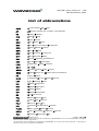
List of abbreviations
ACM Accumulated Call Meter
AT ATtention (prefix for modem commands)
CS Coding Scheme
CTS Clear To Send
DC Direct Current
DCD Data Carrier Detect
DCE Data Communication Equipment
DCS Digital Cellular System
DSR Data Set Ready
DTE Data Terminal Equipment
DTR Data Terminal Ready
EMI ElectroMagnetic Interference
ESD ElectroStatic Discharges
FAQ Frequently Asked Question
GND GrouND
GPRS General Packet Radio Service
GSM Global System for Mobile communications
I/O Input / Output
ISDN Integrated Service Digital Network
LED Light Emitting Diode
ME Mobile Equipment
MO Mobile Originated
MS Mobile Station
MT Mobile Terminated
NC Not Connected
PCL Power Control Level
PDP Packet Data Protocol
PDU Protocol Data Unit
PIN Personal Identification Number
PLMN Public Land Mobile Network
PSTN Public Switched Telephone Network
PUK Personal Unblocking Key

WM_PRJ_M12_UGD_001 - 002
18th September 2003
confidential ©
Page :
7 / 38
This document is the sole and exclusive property of WAVECOM. Not to be distributed or divulged
without prior written agreement.
Ce document est la propriété exclusive de WAVECOM. Il ne peut être communiqué ou divulgué à
des tiers sans son autorisation préalable.
RF Radio Frequency
RFI Radio Frequency Interference
RI Ring Indicator
RTS Request To Send
RX Receive
SIM Subscriber Identification Module
SMS Short Message Service
TX Transmit
VRMS Volt Root Mean Square
VSWR Voltage Standing Wave Ratio

WM_PRJ_M12_UGD_001 - 002
18th September 2003
confidential ©
Page :
8 / 38
This document is the sole and exclusive property of WAVECOM. Not to be distributed or divulged
without prior written agreement.
Ce document est la propriété exclusive de WAVECOM. Il ne peut être communiqué ou divulgué à
des tiers sans son autorisation préalable.
Contents
1
General description..................................................................... 10
1.1
Presentation ..........................................................................................10
1.2
External connections .............................................................................11
1.2.1
Connectors ....................................................................................11
1.2.2
Power supply cable .......................................................................14
1.3
Package content ....................................................................................14
2
Functional description ................................................................ 15
2.1
Architecture ..........................................................................................15
2.2
RS232 serial link....................................................................................16
2.2.1
General presentation......................................................................16
2.2.2
Pin out description.........................................................................17
2.3
RESET ...................................................................................................17
2.3.1
General presentation......................................................................17
2.3.2
Reset sequence .............................................................................18
2.4
BOOT ....................................................................................................18
3
Characteristics ........................................................................... 19
3.1
Basic services........................................................................................19
3.2
Physical characteristics .........................................................................20
3.3
Electrical characteristics ........................................................................20
3.3.1
Power supply ................................................................................20
3.3.2
RF characteristics ..........................................................................22
3.3.3
SIM card........................................................................................23
3.3.4
Audio interface ..............................................................................23
3.4
Environmental characteristics................................................................24
3.5
Protections ............................................................................................24
4
Using the modem........................................................................ 25
4.1
Getting started with the modem............................................................25
4.1.1
Mounting the modem....................................................................25
4.1.2
Setting up the Fastrack modem .....................................................25
4.1.3
Checking the communication with the modem..............................26
4.1.4
Resetting the modem ....................................................................26
4.2
Operational status of the modem ..........................................................27
4.3
Verifying the received signal strength....................................................27
4.4
Verifying the network registration of the modem...................................28

WM_PRJ_M12_UGD_001 - 002
18th September 2003
confidential ©
Page :
9 / 38
This document is the sole and exclusive property of WAVECOM. Not to be distributed or divulged
without prior written agreement.
Ce document est la propriété exclusive de WAVECOM. Il ne peut être communiqué ou divulgué à
des tiers sans son autorisation préalable.
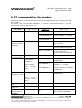
5
AT commands for the modem..................................................... 29
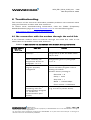
6
Troubleshooting.......................................................................... 30
6.1
No connection with the modem through the serial link .........................30
6.2
Receiving “ERROR” message ................................................................31
6.3
Receiving “No carrier” message ............................................................33
7
Safety recommendations ............................................................ 36
7.1
General Safety .......................................................................................36
7.2
Vehicle Safety........................................................................................37
7.3
Care And Maintenance..........................................................................37
7.4
Your Responsibility................................................................................37
8
Recommended accessories ......................................................... 38
La page charge ...

WM_PRJ_M12_UGD_001 - 002
18th September 2003
confidential ©
Page :
11 / 38
This document is the sole and exclusive property of WAVECOM. Not to be distributed or divulged
without prior written agreement.
Ce document est la propriété exclusive de WAVECOM. Il ne peut être communiqué ou divulgué à
des tiers sans son autorisation préalable.
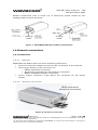
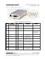
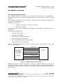
Modem mechanical case is made out of aluminium profile ended by two
holding bridles at each extremity.
Figure 1: FASTRACK M1206 modem presentation
1.2 External connections
1.2.1 Connectors
1.2.1.1 General
FASTRACK M1206 modem has three external connections:
•
Antenna connector: SMA connector for RF connection to the antenna,
•
Sub D high density 15-pin connector for:
o
RS232 serial link connection,
o
Audio lines (microphone and speaker) connection,
o
BOOT and RESET signals connection.
•
Power supply connector: 4-pin Micro FIT connector for DC Power
Supply.
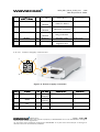
1.2.1.2 Antenna connector
SMA connector
(antenna connector)
Figure 2: Antenna connector
Holding
bridle
Holding
bridle

WM_PRJ_M12_UGD_001 - 002
18th September 2003
confidential ©
Page :
12 / 38
This document is the sole and exclusive property of WAVECOM. Not to be distributed or divulged
without prior written agreement.
Ce document est la propriété exclusive de WAVECOM. Il ne peut être communiqué ou divulgué à
des tiers sans son autorisation préalable.
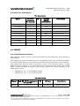
1.2.1.3 Sub HD 15-pin connector
1 2 3 4 5
6 7 8 9 10
15
14 13 11 12
Figure 3: Sub HD 15-pin connector
Pin # Signal
(CCITT / EIA)
I/O I/O type Description Comment
1
CT109 / DCD
O STANDARD
RS232
RS232
Data Carrier Detect
2 CT103 / TX I STANDARD
RS232
RS232
Transmit serial data
3 BOOT I CMOS Boot Active low. Pull
down through
1K for Flash
downloading
4 Microphone (+) I Analog Microphone
positive line
5 Microphone (-) I Analog Microphone
negative line
6 CT104 / RX O STANDARD
RS232
RS232
Receive serial data
7 CT107 / DSR O STANDARD
RS232
RS232
Data Set Ready
8 CT108-2 / DTR I STANDARD
RS232
RS232
Data Terminal Ready
9 GND - GND Ground
10 Speaker (+) O Analog Speaker
positive line

WM_PRJ_M12_UGD_001 - 002
18th September 2003
confidential ©
Page :
13 / 38
This document is the sole and exclusive property of WAVECOM. Not to be distributed or divulged
without prior written agreement.
Ce document est la propriété exclusive de WAVECOM. Il ne peut être communiqué ou divulgué à
des tiers sans son autorisation préalable.
Pin # Signal
(CCITT / EIA)
I/O I/O type Description Comment
11 CT106 / CTS O STANDARD
RS232
RS232
Clear To Send
12 CT105 / RTS I STANDARD
RS232
RS232
Request To Send
13 CT125 / RI O STANDARD
RS232
RS232
Ring Indicator
14 RESET I/O Schmitt Modem reset Active low
15 Speaker (-) O Analog Speaker
negative line
1.2.1.4 Power supply connector
1
2
3
4
Figure 4: Power supply connector
Pin # Signal I/O I/O type Description Comment
1
V+BATT
I Power
supply
Battery input High current
2
GND
Power
supply
Ground
3
NC
Reserved
4
NC
Reserved

WM_PRJ_M12_UGD_001 - 002
18th September 2003
confidential ©
Page :
14 / 38
This document is the sole and exclusive property of WAVECOM. Not to be distributed or divulged
without prior written agreement.
Ce document est la propriété exclusive de WAVECOM. Il ne peut être communiqué ou divulgué à
des tiers sans son autorisation préalable.
1.2.2 Power supply cable
Figure 5: Power supply cable
Component Characteristics
MICRO FIT connector
4-pin
Part number: MOLEX 43025-0400
Cable
Cable length:
∼
1.5 m
Core: tinned copper 24 x 0.2 mm Wire
Section: 0.75 mm
2
1.3 Package content
The Fastrack modem M1206 package includes:
1 Fastrack Modem M1206,
2 holding bridles,
1 Power supply cable + integrated fuse,
1 specification sheet of the modem.
Fuse F 2.5 A / L 250 V
(5 x 20 mm)
Red Black

WM_PRJ_M12_UGD_001 - 002
18th September 2003
confidential ©
Page :
15 / 38
This document is the sole and exclusive property of WAVECOM. Not to be distributed or divulged
without prior written agreement.
Ce document est la propriété exclusive de WAVECOM. Il ne peut être communiqué ou divulgué à
des tiers sans son autorisation préalable.
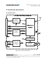
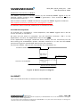
2 Functional description
2.1 Architecture
WISMO Quik
Q2406B
RS232
Interface
SMA
Audio
Interface
DC / DC
Power
Supply
BOOT
RESET
V+BATT
GROUND
Micro-FIT
4 pins
SUB HD
15 pins
VCC
Microphone
Microphone
Speaker
Speaker
VCC
VCC
3V / 5V SIM
Power Supply
SIM card
Socket
SIM card
Holder
Operating
Status
M1206 FASTRACK MODEM
VCC
Figure 6: Functional architecture
La page charge ...

WM_PRJ_M12_UGD_001 - 002
18th September 2003
confidential ©
Page :
17 / 38
This document is the sole and exclusive property of WAVECOM. Not to be distributed or divulged
without prior written agreement.
Ce document est la propriété exclusive de WAVECOM. Il ne peut être communiqué ou divulgué à
des tiers sans son autorisation préalable.
2.2.2 Pin out description
Pin description
2.3 RESET
2.3.1 General presentation
This signal is used to force a reset procedure by providing low level during at
least 500 µs.
This signal has to be considered as an emergency reset only. A reset procedure
is automatically driven by an internal hardware during the power-up sequence.
This signal can also be used to provide a reset to an external device. It then
behaves as an output. If no external reset is necessary this input can be left
open, if used (emergency reset), it has to be driven by an open collector or an
open drain output:
•
RESET pin 14 = 0, for Modem Reset,
•
RESET pin 14 = 1, for normal mode.
Pin description
Signal Sub HD 15-Pin connector
Pin number
I/O I/O type Description
RESET 14 I/O SCHMITT Modem Reset
Signal Sub HD
connector
Pin number
I/O I/O type
RS232
STANDARD
Description
CT103/TX 2 I TX Transmit serial data
CT104/RX 6 O RX Receive serial data
CT105/RTS 12 I RTS Request To Send
CT106/CTS 11 O CTS Clear To Send
CT107/DSR 7 O DSR Data Set Ready
CT108-2/DTR 8 I DTR Data Terminal Ready
CT109/DCD 1 O DCD Data Carrier Detect
CT125/RI 13 O RI Ring Indicator
CT102/GND 9 Ground
La page charge ...
La page charge ...

WM_PRJ_M12_UGD_001 - 002
18th September 2003
confidential ©
Page :
20 / 38
This document is the sole and exclusive property of WAVECOM. Not to be distributed or divulged
without prior written agreement.
Ce document est la propriété exclusive de WAVECOM. Il ne peut être communiqué ou divulgué à
des tiers sans son autorisation préalable.
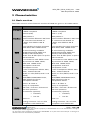
3.2 Physical characteristics
Dimensions 98 x 54 x 25 mm (excluding connectors)
Overall Dimension 110 x 54 x 25 mm
Weight
<105 grams
Volume
132.3 cm
3
Housing
Aluminium profiled
3.3 Electrical characteristics
3.3.1 Power supply
Table 1:
Electrical characteristics
5 V to 32 V DC (GSM or DCS).
Operating Voltage
ranges
5.5 V to 32 V DC (GPRS Class 10).
Maximum current 480 mA Average at 5.5V.
1.7 A Peak at 5V.
Note: the modem is permanently powered once the power supply is
connected. The following table describes the consequences of overvoltage and
undervoltage with the Fastrack Modem.
Table 2:
Effects of power supply defect
If the voltage : Then:
falls below 5V
The GSM communication is not guaranteed.
falls below 5.5V
The GPRS Class 10 is not guaranteed.
Voltage over 32V
(Transient peaks)
The modem guarantees its own protection.
Voltage over 32V
(continuous overvoltage)
Protection of the modem by the fuse (the
supply voltage is disconnected).
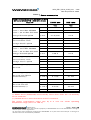
The following table provides information on power consumption of the
Fastrack modem, assuming an operating temperature of +25 °C and using a
3 V SIM card.
La page charge ...

WM_PRJ_M12_UGD_001 - 002
18th September 2003
confidential ©
Page :
22 / 38
This document is the sole and exclusive property of WAVECOM. Not to be distributed or divulged
without prior written agreement.
Ce document est la propriété exclusive de WAVECOM. Il ne peut être communiqué ou divulgué à
des tiers sans son autorisation préalable.
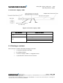
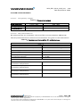
3.3.2 RF characteristics
3.3.2.1 Frequency ranges
Table 4:
Frequency ranges
Characteristic
E-GSM 900 DCS 1800
Frequency TX 880 to 915 MHz 1710 to 1785 MHz
Frequency RX 925 to 960 MHz 1805 to 1880 MHz
3.3.2.2 RF performances
RF performances are compliant with the ETSI recommendation
GSM
05.05.
The RF performances for receiver and transmitter are given in the table below.
Table 5:
Receiver and transmitter RF performances
Receiver
E-GSM900 Reference Sensitivity -104 dBm Static & TUHigh
DCS1800 Reference Sensitivity -102 dBm Static & TUHigh
Selectivity @ 200 kHz > +9 dBc
Selectivity @ 400 kHz > +41 dBc
Linear dynamic range 63 dB
Co-channel rejection >= 9 dBc
Transmitter
Maximum output power (E-GSM 900)
at ambient temperature
33 dBm +/- 2 dB
Maximum output power (DCS1800
at ambient temperature
30 dBm +/- 2 dB
Minimum output power (E-GSM 900)
at ambient temperature
5 dBm +/- 5 dB
Minimum output power (DCS1800)
at ambient temperature
0 dBm +/- 5 dB

WM_PRJ_M12_UGD_001 - 002
18th September 2003
confidential ©
Page :
23 / 38
This document is the sole and exclusive property of WAVECOM. Not to be distributed or divulged
without prior written agreement.
Ce document est la propriété exclusive de WAVECOM. Il ne peut être communiqué ou divulgué à
des tiers sans son autorisation préalable.
3.3.2.3 External antenna
The external antenna is connected to the modem via the SMA connector.
The external antenna must fulfill the characteristics listed in the table below.
Table 6:
External antenna characteristics
Antenna frequency range Dual-band GSM 900/DCS 1800 MHz
Impedance 50 Ohms
Gain (antenna + cable) 0 dBi
VSWR (antenna + cable) -10 dB
Note: refer to chapter 8 for recommended antenna.
3.3.3 SIM card
Table 7:
SIM card characteristics
SIM card 3V or 5V
3.3.4 Audio interface
The audio interface is available through the Sub HD 15-pin connector.
The following table provides electrical information of the audio interface for
handset.
Table 8:
Audio interface characteristics for handset
For GSM 900/DCS 1800 Min Typ Max Unit
Microphone input voltage at
minimum gain
43.8 mVrms
Speaker output voltage at
maximum gain
1.74 Vrms
Speaker impedance 32 50
Ω

WM_PRJ_M12_UGD_001 - 002
18th September 2003
confidential ©
Page :
24 / 38
This document is the sole and exclusive property of WAVECOM. Not to be distributed or divulged
without prior written agreement.
Ce document est la propriété exclusive de WAVECOM. Il ne peut être communiqué ou divulgué à
des tiers sans son autorisation préalable.
3.4 Environmental characteristics
To ensure the proper operation of the Fastrack Modem, the operating
environment must be within a specific temperature as described in the table
below.
Table 9:
Ranges of temperature
Operating temperature range -20 °C to +55 °C
Storage temperature range -25 °C to +70°C
3.5 Protections
The modem is protected by a fuse directly bonded on the power supply cable.
The model of fuse used is: F 2.5 A L 250 V.
The modem is also protected against voltage over +32 V.
When input voltages exceed +32 V, the supply voltage is disconnected in order
to protect the internal electronic components from an overvoltage.
Filtering guarantees:
EMI/RFI protection in input and output,
Signal smoothing.
La page charge ...
La page charge ...
La page charge ...

WM_PRJ_M12_UGD_001 - 002
18th September 2003
confidential ©
Page :
28 / 38
This document is the sole and exclusive property of WAVECOM. Not to be distributed or divulged
without prior written agreement.
Ce document est la propriété exclusive de WAVECOM. Il ne peut être communiqué ou divulgué à
des tiers sans son autorisation préalable.
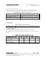
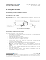
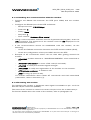
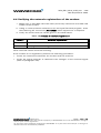
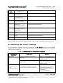
4.4 Verifying the network registration of the modem
1. Make sure a valid SIM card has been previously inserted in the SIM card
holder of the modem.
2. Using a communication software such as HyperTerminal program, enter
the following AT command:
AT+CREG?
.
Value appears as a response.
3. Verify the result with the values given in the table below.
Table 12:
Values of network registration
Value(*) Network registration
0,1 Yes
0,5 Yes (registered roaming)
(*) refer to AT commands documentation [1] for further information about the
other returned values and their meaning.
If the modem is not registered, perform the following procedure:
Check the connection between the modem and the antenna.
Verify the signal strength to determine the strength of the received signal
(refer to paragraph 4.3).
La page charge ...
La page charge ...
La page charge ...
La page charge ...
La page charge ...
La page charge ...

WM_PRJ_M12_UGD_001 - 002
18th September 2003
confidential ©
Page :
35 / 38
This document is the sole and exclusive property of WAVECOM. Not to be distributed or divulged
without prior written agreement.
Ce document est la propriété exclusive de WAVECOM. Il ne peut être communiqué ou divulgué à
des tiers sans son autorisation préalable.
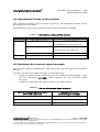
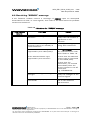
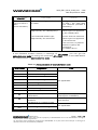
Error Code Diagnostic Hint
3, 6, 8, 29,
34, 38, 41,42,
43, 44, 47,
49, 57, 58,
63, 65, 69,
70, 79, 254
Network causes
See AT commands manual for
further details or call network
provider.
Note: For all other codes, and/or details, see AT commands documentation.
La page charge ...
La page charge ...
La page charge ...
-
 1
1
-
 2
2
-
 3
3
-
 4
4
-
 5
5
-
 6
6
-
 7
7
-
 8
8
-
 9
9
-
 10
10
-
 11
11
-
 12
12
-
 13
13
-
 14
14
-
 15
15
-
 16
16
-
 17
17
-
 18
18
-
 19
19
-
 20
20
-
 21
21
-
 22
22
-
 23
23
-
 24
24
-
 25
25
-
 26
26
-
 27
27
-
 28
28
-
 29
29
-
 30
30
-
 31
31
-
 32
32
-
 33
33
-
 34
34
-
 35
35
-
 36
36
-
 37
37
-
 38
38


Wavecom FASTRACK M1306B Mode d'emploi
- Catégorie
- La mise en réseau
- Taper
- Mode d'emploi
dans d''autres langues
- English: Wavecom FASTRACK M1306B User guide
Documents connexes

Autres documents
-
Electrolux CONTROLBOX 24/7 Manuel utilisateur
-
Patton electronic TV Converter Box IC-V.24 Manuel utilisateur
-
-
AEQ Swing Quick User Manual
-
Black Box TL073A-R4 Le manuel du propriétaire
-
RIKA GSM INTERNO Assembly And Operating Manual
-
CARLO GAVAZZI BH4-CTRLAG Guide d'installation
-
 Inno media InfoWave 24212 Manuel utilisateur
-
Hirschmann 920.061.002 Fiche technique
-
Sixnet VT Guide d'installation
