Faber OSTR30SS400 Le manuel du propriétaire
- Catégorie
- Hottes
- Taper
- Le manuel du propriétaire

OSTR30SS400
OSTR36SS400
Installation Instructions
Use and Care Information
Instructions d'installation
Utilisez et d'entretien
OSTRO

2
READ AND SAVE THESE INSTRUCTIONS BEFORE YOU START
INSTALLING THIS RANGEHOOD
WARNING: - TO REDUCE THE RISK OF A RANGE TOP GREASE FIRE:
a) Never leave surface units unattended at high settings. Boilovers cause smoking and
greasy spillovers that may ignite. Heat oils slowly on low or medium setting.
b)AlwaysturnhoodONwhencookingathighheatorwhenambeingfood(i.e.Crepes
Suzette, Cherries Jubilee, Peppercorn Beef Flambé).
c) Clean ventilating fans frequently. Grease should not be allowed to accumulate on fan
orlter.
d) Use proper pan size. Always use cookware appropriate for the size of the surface element.
WARNING: - TO REDUCE THE RISK OF INJURY TO PERSONS IN THE EVENT OF A
RANGE TOP GREASE FIRE, OBSERVE THE FOLLOWING*:
a)SMOTHERFLAMESwithaclose-ttinglid,cookiesheet,ormetaltray,thenturnofftheburner.
BECAREFULTOPREVENTBURNS.IftheamesdonotgooutimmediatelyEVACUATE
AND CALL THE FIRE DEPARTMENT.
b) NEVER PICK UP A FLAMING PAN - You may be burned.
c) DO NOT USE WATER, including wet dishcloths or towels - a violent steam explosion will
result.
d) Use an extinguisher ONLY if:
1. You know you have a Class ABC extinguisher, and you already know how to operate it.
2. Thereissmallandcontainedintheareawhereitstarted.
3. Theredepartmentisbeingcalled.
4. Youcanghttherewithyourbacktoanexit.
* Based on "Kitchen Firesafety Tips" published by NFPA
WARNING - TO REDUCE THE RISK OF FIRE OR ELECTRIC SHOCK, do not use this
fan with any solid-state speed control device.
WARNING - TO REDUCE THE RISK OF FIRE, ELECTRICAL SHOCK, OR INJURY TO
PERSONS, OBSERVE THE FOLLOWING:
1. Use this unit only in the manner intended by the manufacturer. If you have any
questions, contact the manufacturer.
2. Before servicing or cleaning unit, switch power off at service panel and lock the
service disconnecting means to prevent power from being switched on acciden-
tally. When the service disconnecting means cannot be locked, securely fasten a
prominent warning device, such as a tag, to the service panel.
CAUTION: For General Ventilating Use Only. Do Not Use To Exhaust Hazardous or
Explosive Materials and Vapors.
WARNING - TO REDUCE THE RISK OF FIRE, ELECTRICAL SHOCK, OR INJURY TO
PERSONS, OBSERVE THE FOLLOWING:
1. InstallationWorkAndElectricalWiringMustBeDoneByQualiedPerson(s)InAccor-
dance With All Applicable Codes And Standards, Including Fire-Rated Construction.
2. Sufcientairisneededforpropercombustionandexhaustingofgasesthrough
theue(chimney)offuelburningequipmenttopreventbackdrafting.Followthe
heating equipment manufacturer's guideline and safety standards such as those
publishedbytheNational FireProtectionAssociation(NFPA),andtheAmerican
SocietyforHeating,RefrigerationandAirConditioningEngineers(ASHRAE),and
the local code authorities.

3
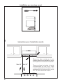
ALL WALL AND FLOOR OPENINGS WHERE THE RANGEHOOD IS INSTALLED MUST
BE SEALED.
This rangehood requires at least 24" of clearance between the bottom of the rangehood
and the cooking surface or countertop. This hood has been approved by UL at this distance
from the cooktop.
This minimum clearance may be higher depending on local building codes. For gas cooktops
and combination ranges, a minimum of 30" is recommended and may be required.
Overhead cabinets on both sides of this unit must be a minimum of 18" above the cooking surface
or countertop. Consult the cooktop or range installation instructions given by the manufacturer
before making any cutouts.
MOBILE HOME INSTALLATION The installation of this rangehood must conform to the
Manufactured Home Construction and Safety Standards, Title 24 CFR, Part 3280 (formerly
Federal Standard for Mobile Home Construction and Safety, Title 24, HUD, Part 280). See
Electrical Requirements.
• Venting system MUST terminate outside the home.
• DO NOT terminate the ductwork in an attic or other enclosed space.
• DO NOT use 4" laundry-type wall caps.
• Flexible-type ductwork is not recommended.
• DO NOT obstruct the ow of combustion and ventilation air.
• Failure to follow venting requirements may result in a re.
WARNING
!
VENTING REQUIREMENTS
Determine which venting method is best for your application. Ductwork can extend either through the
wall or the roof.
The length of the ductwork and the number of elbows should be kept to a minimum to provide efcient
performance. The size of the ductwork should be uniform. Do not install two elbows together. Use
duct tape to seal all joints in the ductwork system. Use caulking to seal exterior wall or oor opening
around the cap.
Flexible ductwork is not recommended. Flexible ductwork creates back pressure and air turbulence
that greatly reduces performance.
Make sure there is proper clearance within the wall or oor for exhaust duct before making cutouts.
Do not cut a joist or stud unless absolutely necessary. If a joist or stud must be cut, then a supporting
frame must be constructed.
WARNING - To Reduce The Risk Of Fire, Use Only Metal Ductwork.
CAUTION-Toreduceriskofreandtoproperlyexhaustair,besuretoductairoutside–Do
not vent exhaust air into spaces within walls or ceilings or into attics, crawl spaces, or garages.
3. When cutting or drilling into wall or ceiling, do not damage electrical wiring and
other hidden utilities.
4. Ducted fans must always be vented to the outdoors.

4
• Electrical ground is required on this rangehood.
• If cold water pipe is interrupted by plastic, nonmetallic gaskets or other materials, DO
NOT use for grounding.
• DO NOT ground to a gas pipe.
• DO NOT have a fuse in the neutral or grounding circuit. A fuse in the neutral or
grounding circuit could result in electrical shock.
• Check with a qualied electrician if you are in doubt as to whether the rangehood is
properly grounded.
• Failure to follow electrical requirements may result in a re.
WARNING
!
StateofCaliforniaProposition65Warning(USonly)
WARNING
This product contains chemicals known to the State of California to cause cancer and birth
defects or other reproductive harm.
For more information go to www.P65Warnings.ca.gov

5
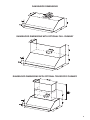
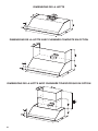
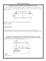
RANGEHOOD DIMENSIONS
RANGEHOOD DIMENSIONS WITH OPTIONAL FULL CHIMNEY
RANGEHOOD DIMENSIONS WITH OPTIONAL TELESCOPIC CHIMNEY
29
15/16
” - 35
3/4
”
29
15/16
” - 35
3/4
”
29
15/16
” - 35
3/4
”

6
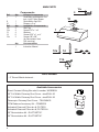
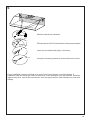
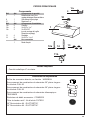
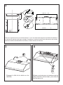
MAIN PARTS
Components
Ref. Qty. Product Components
1 1 Hood Body, complete with: Con-
trols, Light, Filters, Blower.
8 1 Recirculation Vent Grill
10 1 Damper ø 5 7/8"
Ref. Qty. Installation Components
11b 2 Wall Plug
12a 4 Screw 3/16" x 1 3/4"
13 4 Washers
14 6 Screws 3/16" x 1 15/16"
12e 2 Screws 1/8"x 3/8"
(for Recirculation Vent
Grill mounting)
Qty. Documentation
1 Instruction Manual
Available Accessories
Parts needed
- 6" Round Metal ductwork .
Direct Connect Wiring Box sku # number: WIREBOX
30" Full Width Chimney Duct Cover - sku#FULL30
36" Full Width Chimney Duct Cover - sku#FULL36
Telescopic Chimney Duct Cover - TELEMAES
CFM Reducer Accessory Kit - CFMRED2
Activated Charcoal Filter sku #; FILTER1
Activated Charcoal Filter sku #; FILTER1LL
30" Recirculation Kit - DUCTGRT30"
36" Recirculation Kit - DUCTGRT36"
Created by
-
Denomination
-
Lang EN
Sheet
1
/1
Modif.by
Approved by
Approval date
Doc. status
Drawing N.
NEW_DRAWING_BOX
Rev
01
10
1
12a
14
13
11b
6
MAIN PARTS
Components
Ref. Qty. Product Components
1 1 Hood Body, complete with:
Controls, Light, Filters,
Blower.
2 2 Bracket
3 2 Cover
8 1 Recirculation Vent Grill
10 1 Damper ø 5 7/8"
1 Remote Control REMCTRL
Ref. Qty. Installation Components
12a 4 Screws 1/8" x 5/8"
12e 2 Screws 1/8"x 3/8"
(for Recirculation Vent
Grill mounting)
Qty. Documentation
1 Instruction Manual
2
12a
3
1
H
Available Accessories
Parts needed
- 6" Round Metal ductwork.
Direct Connect Wiring Box sku # number: WIREBOX
Make-Up Air Dampers:
6" Make-Up Air Damper Kit MUDAMPER6
8" Make-Up Air Damper Kit MUDAMPER8
Standard Liner 30- LINE30ST
Standard Liner 36 - LINE36ST
Activated Charcoal Filter sku #; FILTER1
CFM Reducer Kit #CFMRED

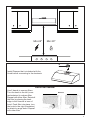
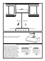
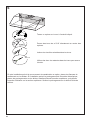
7
Min.24" Min.30"
H
I
Install Damper that is included with the
Hood before connecting to the ductwork.
Use 2 hands to remove filters.
Turn the knob to the left (coun-
terclockwise) to release filter.
Repeat with other filter. Reinstall
the filter by placing the back
edge in the channel at rear of
hood. Push filter into place, turn
the knob to the right (clockwise)
to attach to range hood. Repeat
with other filter.
BafeFilterRemoval
Removal / Déplacement
Removal

8
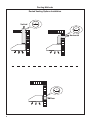
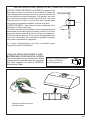
Ducted Venting Options Installation
Horizontal
Vertical
6"
6"
Rear
6"
Ducting Methods

9
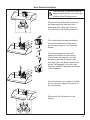
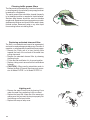
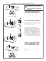
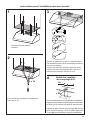
Rear Ducted Installation
The Electrical Connector must be
removed first before converting the
hood to Rear Ducting mode.
For a horizontal ducting installation
the motor needs to be unsecured
by first removing the 12 screws as
shown.
Once the screws are removed,
extract the blower from the body
of the Hood and position it so the
transition opening is facing to the
rear wall (from the back remove and
rotate 180 degrees to the left, and
then ip it back 90 degrees as shown
in the diagram).
Once the blower is in place re-install
the 12 screws to fasten the motor to
the Hood body.
Disconnect the Electrical Connector
by depressing the tabs with your
hand and also using light force on
one tab with a at head screwdriver.
Reconnect the Connector to the
blower.

10
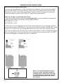
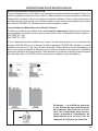
RECIRCULATION INSTRUCTIONS
RECIRCULATING INSTALLATIONS
For recirculating installations, Charcoal Filters are necessary. Remove all grease filters
and set aside. Attach one charcoal filter to each end of the blower. Each charcoal filter
attaches to the grid on the side of the blower. Rotate the filter clockwise to install and
counterclockwise to remove (FIGURE 3C). Replace all grease filters.
There are 2 ways to recirculate the Ostro:
1) Use the Ductless Recirculating Kit (sold separately), refer to installation instructions
inside the Recirculating Kit which includes charcoal filters.
DUCTGRT30" - (30")
DUCTGRT36" - (36")
2) Duct work must be installed to exhaust the rangehood back into the kitchen, either at
the top of the cabinet (FIGURE 3A) or at the face or side of the soffit (FIGURE 3B). Install
at least 15" of metal duct (fig.3A and 3B) at the air exit. Run the duct vertically and se-
cure it at the opening cut out at the top or side of the cabinet or soffit. Installation of metal
grill is recommended. This duct work must not terminate into a dead air space. FILTER1
must be purchased to complete this type of installation.
This page needs to be inserted
after Page 9 and before Page 10
Add the new
kit
:DUCTGRT42
–(42“)
This page needs to be inserted
after Page 9 and before Page 10
Add the new
kit
:DUCTGRT42
–(42“)
Note: It is recommended that pro-
fessional style cooking always be
vented to the outside; for recirculat-
ing Installations, some duct work is
required to exhaust the unit out of
the cabinet.

11
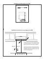
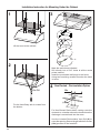
Installation for Mounting on the Wall
==
Installation Instruction for mounting on the Wall
Draw a vertical line on the supporting wall
as high as practical, at the center of the
area in which the hood will be installed.
Draw a horizontal line at where the bottom
edge of the hood will be located as indicated
in the figure that is a minimum of 24"- 30"
above cooking surface
1
Min.24" Min.30"

12
2
´
[
[
24” - 30”
24” - 30”
L
/ ´´
7 13/16”
Mark the wall where indicated, 7 13/16" above the horizontal line and at L distance on the left and
right of vertical line. The distance L change for all dimension of Hood.
Insert the two wall plugs in the holes as shown and fix.
3
4
E
E
Hook the hood body onto the wall plugs.
Use a level to insure that Fixing Bracket is
level and then fully secure the two screws.

13
5
´
[
[
[
Mark the wall where indicated.
Drill directly into ø 5/16" holes at all the center points marked.
Insert the purchased wall plugs in the holes.
Using two remaining screws to anchor the hood in holes.
If your installation uses the optional duct cover, fit the cover anges over the brackets. If
installation uses the telescopic chimney extension, fit the extension over the brackets. Install the
upper section first, then fit the lower section over the upper section. Seal extension to hood with
clamps.
12a + 13

14
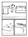
Installation Instruction for Mounting Under the Cabinet
[
Lift the hood to the cabinet.
Fix the Hood Body with 4 screws from
the bottom.
Mark the wall where indicated.
Drill directly into ø 5/16" holes at all the center
points marked.
Insert the purchased wall plugs in the holes.
Using two remaining screws to anchor the hood
in holes.
1
´
[
[
[
3
4
12a + 13
[
2
6 x 14
Non Ducted - Recirculation Option
For Non-Ducted Recirculation venting route the
ductwork to a location above the hood where the
discharge is vented back into the room.
Use the included Recirculation Vent Grill (8) to
cover the opening. Secure the grill with the 2 screws
(12e) provided in the Install Kit.
´
8
12e

15
INSTALLATION CONTINUED
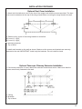
Optional Duct Cover Installation
1. Attach the full-width duct cover to the top of the range hood
with the screws provided. The duct cover must be attached
to the top of the range hood before mounting the range hood
to the wall.
A: Distance from center of mounting bracket to centerline:
30" hood: 13 15/32" / 36" hood: 16 15/32" /
42" hood: 19 15/32" / 48" hood: 22 15/32"
B: Mounting brackets
C: Top of hood
2. Install each bracket on the wall as shown. Make sure the
screws and brackets are securely fastened to the wall.
IMPORTANT: Install only the brackets. Do not install the
hood.
Optional Telescopic Chimney Extension Installation
1. If a chimney extension is used, attach the extension brackets
as shown. Make sure that the screws are securely fastened to
the wall.
A: Ceiling
B: Brackets
C. Top of hood
INSTALLATION CONTINUED
1. Attach the full-width duct cover to the top of the range hood with the screws provided. The duct
cover must be attached to the top of the range hood before mounting the range hood to the wall.
A: Distance from center of mounting bracket to centerline:
30" hood: 13 15/32"
36" hood: 16 15/32"
42" hood: 19 15/32"
B: Mounting brackets
C: Top of hood
2. Install each bracket on the wall as shown. Make sure the screws and brackets are securely
fastened to the wall. IMPORTANT: Install only the brackets. Do not install the hood.
Optional Duct Cover Installation
INSTALLATION CONTINUED
Optional Duct Cover Installation
1. Attach the full-width duct cover to the top of the range hood
with the screws provided. The duct cover must be attached
to the top of the range hood before mounting the range hood
to the wall.
A: Distance from center of mounting bracket to centerline:
30" hood: 13 15/32" / 36" hood: 16 15/32" /
42" hood: 19 15/32" / 48" hood: 22 15/32"
B: Mounting brackets
C: Top of hood
2. Install each bracket on the wall as shown. Make sure the
screws and brackets are securely fastened to the wall.
IMPORTANT: Install only the brackets. Do not install the
hood.
Optional Telescopic Chimney Extension Installation
1. If a chimney extension is used, attach the extension brackets
as shown. Make sure that the screws are securely fastened to
the wall.
A: Ceiling
B: Brackets
C. Top of hood
Optional Telescopic Chimney Extension Installation
1. If a chimney extension is used, attach the extension brackets as shown. Make sure that the
screws are securely fastened to the wall.
A: Ceiling
B: Brackets
C: Top of hood

16
Direct Connect Wiring Box
Accessory sku # WIREBOX
(purchased separately)
Created by
-
Denomination
-
Lang EN
Sheet
1
/1
Modif.by
Approved by
Approval date
Doc. status
Drawing N.
NEW_DRAWING_BOX
Rev
01
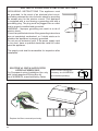
ELECTRICAL INSTALLATION WITH CONNECTION CABLE
ELECTRICAL INSTALLATION WITH
OPTIONAL WIRING BOX
For Permanent wiring Installation-Use only
with Listed rangehood Wiring Box kit
sku # WIREBOX, manufactured by Faber.
Max. 33 7/16”
GROUNDING INSTRUCTIONS This appliance must
be grounded. In the event of an electrical short circuit,
grounding reduces the risk of electric shock by providing
an escape wire for the electric current. This appliance
is equipped with a cord having a grounding wire with a
grounding plug. The plug must be plugged into an outlet
that is properly installed and grounded.
WARNING - Improper grounding can result in a risk of
electric shock.
Consult a qualified electrician if the grounding instructions
are not completely understood, or if doubt exists as to
whether the appliance is properly grounded.
Do not use an extension cord. If the power supply cord
is too short, have a qualified electrician install an outlet
near the appliance.
The supply cord shall be accessible for inspection after
installation.
Replace the filters removed previously.

17
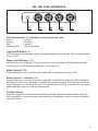
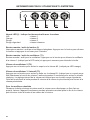
USE AND CARE INFORMATION
,
LED indicator light (I) - indicates current speed with color
Green - speed 1
Orange - speed 2
Red - speed 3
Flashing Red - intensive speed
Light On/Off Button ( L )
On/Off switch for the halogen lights. Press the button to turn the light ON and press again
to turn it OFF.
Blower On/Off Button ( T1 )
On/Off button for the blower. Press the button to turn the blower ON to speed one (indi-
cated by green LED) and press again to turn the hood off
Blower Speed 2 (T2)
Press this button to turn the hood onto speed #2. (indicated by orange LED)
Blower Speed 3 / Intensive (T3)
Press this button to turn the hood onto speed #3. (indicated by solid red LED) Hold down
the speed 3 button for 2 seconds to activate the intensive speed. The intensive speed set-
ting is indicated by a blinking red light. This operates the hood for 6 minutes on the highest
speed and then returns to the previous speed.
For Best Results
Start the rangehood several minutes before cooking to develop proper airow. Allow the
unit to operate for several minutes after cooking is complete to clear all smoke and odors
from the kitchen.

18
Cleaningbafegreaselters
The lters must be cleaned every 2 months of operation,
or more frequently for particularly heavy usage, and can
be washed in a dishwasher.
The metal grease lters should be cleaned frequently
in hot detergent solution or washed in the dishwasher.
Stainless steel cleaner should be used on stainless
rangehoods. Abrasives and scouring agents can scratch
stainless steel nishes and should not be used to clean
nished surface. Remove all water or any other liquid
from washing before re-installing lters.
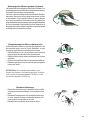
Replacingactivatedcharcoallter
The lter is not washable and cannot be regenerated,
and must be replaced approximately every 4 months of
operation, or more frequently for particularly heavy usage.
• Remove the Filters one at a time, pushing them
towards the back of the unit and at the same time
pulling downward.
• Remove the saturated charcoal lter by releasing
the xing hooks.
• Fit the new lter and fasten it in its correct position.
• Replace, taking care to ensure that the handle faces
forwards.
• CAUTION : When used in recirculation mode, to
Reduce the Risk of Fire and Shock use only conver-
sion kit Model FILTER 1 or kit Model FILTER 1LL.
Lighting unit
• Remove the snap-on lamp cover by levering it from
under the metal ring, supporting it with one hand.
• Replace the lamp with a new one of the same type,
making sure that you insert the two pins properly into
the housings on the lamp holder.
• Replace the snap-on lamp cover.

19
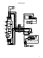
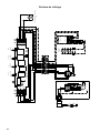
Wiring Diagram
0 1 2 3 4 5 6 7 8 9
H90_021
02
Drawing N : Rev :
Modif. by
Doc.status
Do not get quotas from the drawing do not bring
modifications without authorization of techincal office.
According to the law we reserve the own of the present
drawing with reproduction prohibition partial or total.
Approved date
Modification description
Approved by
SCHEMA ELETTRICO M8-4V ESZ
Doc Type
Denomination
Creation date
16.Feb.2018
CORRADO DOLCE
Created by
991.0349.116
Code
220-240V ~50Hz
220~60Hz
110-127V 60Hz
F N
BLU
PNK
BRW
WHT
1
2
3
4
5
6
BLK
Y-G
123
654
987
PNK
M8-4V
BRW
ORG
M1
V1
MC
F
V2
ESZ
BRWWHT
L-BBLU
BLK
GRY
BLK
GRY
123
654
789
0-1
MOTOR
L-B
BRW
1
1
BRW
BRW
L-B
2
2
L-B
BLK
3
3
BLK
GRY
4
4
GRY
2
SPEED
BLU
5
5
BLU
BLU
PNK
6
6
PNK
PNK
WHT
7
7
WHT
WHT
VLT(org)
8
8
VLT(org)
RED(org)
9
9
RED(org)
10
10
3/I
SPEED
11
11
12
12
HALOGEN
LAMPS
0-1
LIGHT
N
L
V4
L
V3
PRI.SEC.
ELECTRONIC
TRNSFORMER
WHT
1
2
3
4
5
6
L-B
BLK
GRY
RED(ORG)
VLT(ORG)
RED
VLT
VLT
INCANDESCENT/HALOGEN
LAMP
RED

20
January 4, 2016
FABER CONSUMER WARRANTY & SERVICE
All Faber products are warranted against any defect in materials or workmanship for the original purchaser
for a period of 1 year from the date of original purchase (requires proof of purchase). This warranty covers
labor and replacement parts. Faber, at its option, may repair or replace the product or components
necessary to restore the product to good working condition. To obtain warranty service, contact the dealer
from whom you purchased the range hood, or the local Faber distributor. If you cannot identify a local Faber
distributor, contact us at (508) 358-5353 for the name of a distributor in your area.
The following is not covered by Faber's warranty:
1. Service calls to correct the installation of your range hood, to instruct you how to use your range hood, to
replace or repair house fuses or to correct house wiring or plumbing.
2. Service calls to repair or replace range hood light bulbs, fuses or filters. Those consumable parts are
excluded from warranty coverage.
3. Repairs when your range hood is used for other than normal, single-family household use.
4. Damage resulting from accident, alteration, misuse, abuse, fire, flood, acts of God, improper installation,
installation not in accordance with electrical or plumbing codes or Faber documentation, or use of products
not approved by Faber.
5. Replacement parts or repair labor costs for units operated outside the United States or Canada, including
any non-UL or C-UL approved Faber range hoods.
6. Repairs to the hood resulting from unauthorized modifications made to the range hood.
7. Expenses for travel and transportation for product service in remote locations and pickup and delivery
charges. Faber range hoods should be serviced in the home.
THIS WARRANTY DOES NOT ALLOW RECOVERY OF INCIDENTAL OR CONSEQUENTIAL DAMAGES, INCLUDING, WITHOUT
LIMITATION, DIRECT, INDIRECT, INCIDENTAL, SPECIAL OR CONSEQUENTIAL DAMAGES, PERSONAL INJURY/WRONGFUL
DEATH OR LOST PROFITS FABER WARRANTY IS LIMITED TO THE ABOVE CONDITIONS AND TO THE WARRANTY PERIOD
SPECIFIED HEREIN AND IS EXCLUSIVE. EXCEPT AS EXPRESSLY SPECIFIED IN THIS AGREEMENT, FABER DISCLAIMS ALL
EXPRESS OR IMPLIED CONDITIONS, REPRESENTATIONS, AND WARRANTIES INCLUDING, WITHOUT LIMITATION, ANY
IMPLIED WARRANTIES OF MERCHANTABILITY OR FITNESS FOR A PARTICULAR PURPOSE
.
This warranty gives you specific legal rights that may vary from state to state.
Model#: ______________________________ Serial #: _____________________________
La page est en cours de chargement...
La page est en cours de chargement...
La page est en cours de chargement...
La page est en cours de chargement...
La page est en cours de chargement...
La page est en cours de chargement...
La page est en cours de chargement...
La page est en cours de chargement...
La page est en cours de chargement...
La page est en cours de chargement...
La page est en cours de chargement...
La page est en cours de chargement...
La page est en cours de chargement...
La page est en cours de chargement...
La page est en cours de chargement...
La page est en cours de chargement...
La page est en cours de chargement...
La page est en cours de chargement...
La page est en cours de chargement...
La page est en cours de chargement...
-
 1
1
-
 2
2
-
 3
3
-
 4
4
-
 5
5
-
 6
6
-
 7
7
-
 8
8
-
 9
9
-
 10
10
-
 11
11
-
 12
12
-
 13
13
-
 14
14
-
 15
15
-
 16
16
-
 17
17
-
 18
18
-
 19
19
-
 20
20
-
 21
21
-
 22
22
-
 23
23
-
 24
24
-
 25
25
-
 26
26
-
 27
27
-
 28
28
-
 29
29
-
 30
30
-
 31
31
-
 32
32
-
 33
33
-
 34
34
-
 35
35
-
 36
36
-
 37
37
-
 38
38
-
 39
39
-
 40
40


Faber OSTR30SS400 Le manuel du propriétaire
- Catégorie
- Hottes
- Taper
- Le manuel du propriétaire
dans d''autres langues
- English: Faber OSTR30SS400 Owner's manual
Documents connexes
-
Faber OSTR30SS400 Guide d'installation
-
-
-
-
-
-
-
-
-
Faber Diamante 48 SS Guide d'installation
