
User information
Notice d’utilisation
Bedienungs-
und Installationsanleitung
Gebruiksaanwijzing en
installatievoorschrift
PAG 6430 E
BE
Gas hob
Table de cuisson
Kochmulde
Gaskookplaat

2
progress
Important Safety Information ............................................................................................ 3
Hob burner control knobs ................................................................................................ 5
Using the hob .................................................................................................................. 7
Cleaning and Maintenance ............................................................................................... 8
Technical data ................................................................................................................ 10
Installation ...................................................................................................................... 11
Adaptation to different types of gas ................................................................................ 12
Electrical Connection ..................................................................................................... 13
Building In ...................................................................................................................... 15
Possibilities for insertion ................................................................................................. 17
Technical assistance and spare parts ............................................................................. 18
Contents
The following symbols will be found in the text to guide you throughout the Instructions:
Safety Instructions
Step by step instructions for an operation
Hints and Tips
Environmental information
Guide to Use the instructions
This appliance complies with the following E.E.C. Directives:
••
••
• 2006/95
(Low Voltage Directive);
••
••
• 89/336 (Electromagnetical Compatibility Directive);
••
••
• 90/396 (Gas Appliances);
••
••
• 93/68 (General Directives) and subsequent modifications.
It is very important that this instruction book should be kept safely for future consultation. If the
appliance should be sold or given to another person, please ensure that the booklet goes
together with it, so that the new owner can know of the functions of the machine and also be
aware of the warnings.
These instructions are only for the countries stated by the symbol printed on the front cover of
this instruction book.
)
MANUFACTURER:
ELECTROLUX HOME PRODUCTS ITALY S.p.A.
Viale Bologna, 298
47100 FORLÌ (Italy)

progress 3
Installation
z The work of installation must be carried out
by competent and qualified installers
according to the regulations in force.
• Any modifications to the domestic
electrical mains which may be necessary
for the installation of the appliance
should be carried out only by competent
personnel.
During Operation
• This appliance has been designed for
non professional purpose in private
houses only. It is meant to cook edible
foodstuff only and must not be used for
any other purposes.
• It is dangerous to alter the specification in
any way.
• For hygiene and safety reasons, this
appliance should be kept clean at all
times. A build-up of fats or other foodstuff
could result in a fire.
• Under no circumstances should you
attempt to repair the appliance yourself.
Repairs carried out by unexperienced
persons may cause injury or serious
malfunctioning. Refer to your local
Service Centre. Always insist on genuine
spare parts.
• Ensure that all control knobs are in the
OFF position when not in use.
• Should you connect any electrical tool to
a plug near this cooking appliance,
ensure that electric cables are not in
contact with it and keep them far enough
from the heated parts of this appliance.
• If the appliance is out of order,
disconnect it from the electric supply.
English
This warnings has been given for the safety of you and others. We therefore ask you to
carefully read the procedures of installing and using this cooker.
Important safety information
People Safety
• This appliance has been designed to be
operated by adults and children under
supervision. Young children must not be
allowed to tamper with the controls or
play near or with the oven.
• This appliance is not intended for use by
children or other persons whose physical,
sensory or mental capabilities or lack of
experience and knowledge prevents
them from using the appliance safely
without supervision or instruction by a
responsible person to ensure that they
can use the appliance safely.
• Accessible parts of this appliance may
become hot when it is in use. Children
should be kept away until it has cooled.
About Installation, Cleaning and
Maintenance
• It is mandatory that all operations
required for the installation are carried out
by a qualified or competent person, in
accordance with existing rules and
regulations.
• Disconnect the appliance from the
electrical supply, before carrying out any
cleaning or manteinance work.
• Ensure a good ventilation around the
appliance. A poor air supply could cause
lack of oxygen.
• Ensure that the gas supply complies with
the gas type stated on the identification
label, placed near the gas supply pipe.
• This appliance is not connected to a
combustion products evacuation device.
It must be installed and connected in
accordance with current installation

4
progress
regulations. Particular attention shall be
given to the relevant requirements
regarding ventilation.
• The use of a gas cooking appliance
results in the production of heat and
moisture in the room in which it is
installed. Ensure that the kitchen is
well ventilated: keep natural
ventilation holes open or install a
mechanical ventilation device
(mechanical extractor hood).
• Prolonged intensive use of the
appliance may call for additional
ventilation, for example opening of a
window, or more effective
ventilation, for example increasing
the level of mechanical ventilation
where present.
• Once you removed all packaging from
the appliance, ensure that it is not
damaged and the electric cable is in
perfect conditions. Otherwise, contact
your dealer before proceeding with the
installation.
• The manufacturer disclaims any
responsability should all the safety
measures not be carried out.
Service
• Under no circumstances should you
attempt to repair the appliance yourself.
Repairs carried out by unexperienced
persons may cause injury or serious
malfunctioning. Refer to your local Service
Centre. Always insist on genuine spare
parts.
Environmental Information
• After installation, please dispose of the
packaging with due regard to safety and
the environment.
• When disposing of an old appliance,
make it unusable, by cutting off the
cable.
The symbol
on the product or
on its packaging indicates that this product
may not be treated as household waste.
Instead it shall be handed over to the
applicable collection point for the recycling of
electrical and electronic equipment. By
ensuring this product is disposed of
correctly, you will help prevent potential
negative consequences for the environment
and human health, which could otherwise be
caused by inappropriate waste handling of
this product. For more detailed information
about recycling of this product, please
contact your local city office, your household
waste disposal service or the shop where
you purchased the product.

progress 5
Hob burner control knobs
The symbols on the knobs mean:
= no gas supply
= maximum gas supply
= minimum gas supply
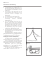
For easier lighting, proceed before
putting a pan on the pan support.
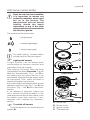
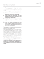
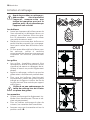
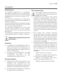
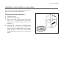
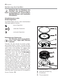
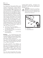
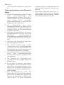
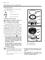
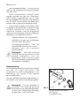
Lighting the burners
To light a burner, turn the relevant knob
anticlockwise to maximum position and
push down the knob to ignite.
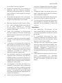
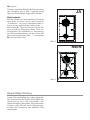
After lighting the flame, keep the knob
pushed down for about 5 seconds. This will
allow the "thermocouple" (Fig.1 - lett. D) to
be heated and the safety device to be
switched off, otherwise the gas supply would
be interrupted. Then, check the flame is
regular and adjust it as required.
If you cannot light the flame even after several
attempts, check the "cap" (Fig.1 - lett. A) and
the"crown" (Fig.1 - lett. B) are in the correct
position.
In the absence of electricity, ignition can
occur without the electrical device; in this
case approach the burner with a flame, push
the relevant knob down and turn it anti-
clockwise until it reaches the "maximum"
position.
To switch off burners
To put the flame out, turn the knob to the
symbol (
z).
)
)
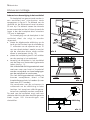
Fig. 1
A
B
D
C
Triple crown
Once the hob has been installed,
it is important to remove any
protective materials, which were
put on in the factory. The
manufacturer will not accept
liability, should the above
instructions or any of the other
safety instructions incorporated in
this book be ignored.
A - Burner cap
B - Burner crown
C - Ignition candle
D - Thermocouple

6
progress
Take care when frying food in hot
oil or fat, as the overheated
splashes could easily ignite.
When switching on the mains, after
installation or a power cut, it is quite
normal for the spark generator to be
activated automatically.
If the burner does not ignite, turn the
control knob to zero, and try again.
Do not keep the control knob
pressed for more than 15 seconds.
If the burner does not light even after 15
seconds, release the control knob, turn
it the “off” position and wait for at least
one minute before trying to light the
burner again.
If the burner accidentally goes out,
t
urn the control knob to the “off”
position and wait for at least 1
minute before trying to light the
burner again.

progress 7
Using the hob correctly
To ensure maximum burner efficiency, you
should only use pots and pans with a flat
bottom fitting the size of the burner used
(see table below).
• For easier lighting, proceed before putting
a pan on the pan support.
• Use only pans or pots with flat bottom.
• Take care when frying food in hot oil
or fat, as the overheated splashes
could easily ignite.
• If you use a saucepan which is smaller
than the recommended size, the flame will
spread beyond the bottom of the vessel,
causing the handle to overheat.
• Prolonged cooking with potstones,
earthenware pans or cast-iron plates
is inadvisable. Also, do not use
aluminium foil to protect the top
during use.
• Make sure pots do not protrude over the
edges of the cooktop and that they are
centrally positioned on the rings in order to
obtain lower gas consumption.
• Do not place unstable or deformed pots
on the rings: they could tip over or spill their
contents, causing accidents.
• Pots must not enter the control zone.
• If the control knobs become difficult to
turn, please contact your local Service
Force Centre.
• As soon as a liquid starts boiling, turn
down the flame so that it will barely keep
the liquid simmering.
Burner Minimum Maximum
diameter diameter
Triple crown burner 180 mm 260 mm
Semirapid burner
rear 120 mm 220 mm
front 120 mm 180 mm
Auxiliary burner 80 mm 160 mm

8
progress
Cleaning and Mainteinance
Disconnect the appliance from
the electrical supply, before
carrying out any cleaning or
manteinance work.
The hob is best cleaned whilst it is
still warm, as spillage can be
removed more easily than if it is
left to cool.
This appliance cannot be cleaned
with steam or with a steam
cleaning machine.
The burners
z The burner caps and crowns can be
removed for cleaning.
z Wash the burners taps and crowns
using hot soapy water, and remove
marks with a mild paste cleaner. A well
moistened soap impregnated steel wool
pad can be used with caution, if the
marks are particularly difficult to remove.
z After cleaning, be sure to wipe dry with a
soft cloth.
z Frequently wash the "caps" and the
"crowns" with hot soapy water, carefully
taking away any built-up of food.
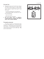
The pan supports
z The enamelled grills can be cleaned with
warm soapy water.
Take care when drying them as the
enamelling process occasionally leaves
rough edges. If necessay, remove
stubborn stains using a paste cleaner.
z After cleaning, make sure that the pan
supports are correctly positioned.
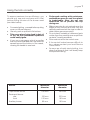
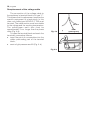
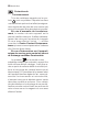
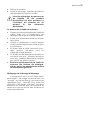
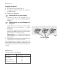
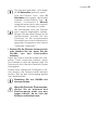
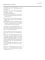
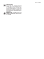
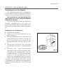
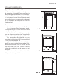
z To make burners work properly, ensure
that pan supports are placed in a way
that the arms are centred upon the
burner as shown in the picture.
z Pay attention when replacing the
pan supports in order to avoid
damaging the hob top.
NO
YES

progress 9
The Hob Top
z Regularly wipe over the hob top using a
soft cloth well wrung out in warm water
to which a little wasing up liquid has
been added. Avoid the use of the
following:
- household detergent and bleaches;
- impregnated pads unsuitable for non-
stick saucepans;
- steel wool pads;
- bath/sink stain removers.
z Do not leave acid or alkaline
substances (e.g. vinegar, salt, lemon
juice, etc.) on the cooktop.
The Ignition electrode
The electric ignition is obtained through
a ceramic electrode with a metal electrode
inside (Fig.1 - C). Keep these components
very clean, to avoid difficult lighting, and
check that the burner crown holes (Fig.1 - B)
are not obstructed.

10
progress
Cut out dimensions
(see chapter “Building In”)
Width: 560 mm
Depth: 480 mm
Overall dimensions
Width: 594 mm
Depth: 510 mm
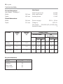
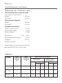
Technical data
Heat Input
Triple Crown burner 4,0 kW
Semi-rapid burner 2,0 kW
Auxiliary burner 1,0 kW
Electric supply: 230 V ~ 50 Hz
Category: II2E+3+
Gas supply: G20/G25 (2E+) 20/25 mbar
Appliance class 3
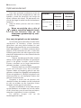
BURNER NORMAL REDUCED NORMAL POWER
POWER POWER
kW kW NATURALPOWER LPG
28-30/37 mbar
m
3
/h g/h
inj.
G20 G25
inj.
G30 G31
100/mm 20 mbar 25 mbar 100/mm
Auxiliary 1,0 0,33 70 0,095 0,111 50 73 71
Semi-rapid 2,0 0,45 96 0,190 0,221 71 145 143
Triple crown 4,0 1,2 146 0,381 0,443 98 291 286
By-pass diameters
Burner Ø By-pass in 1/100 mm.
Auxiliary 28
Semi-rapid 32
Triple crown 56

progress 11
Installation
z The following instructions about
installation and maintenance must
be carried out by qualified personnel
in compliance with the regulation in
force. The regulation to be applied
for this type of installation is NBN D
5I.003 : "Installations functioning
with combustible gas lighter than
air".
z The side walls of the unit in which
the hob is going to be installed, must
not exceed the height of the working
top.
z Avoid installing the appliance in the
proximity of inflammable materials
(e.g. curtains, tea towels etc.).
z The appliance must be electrically
disconnected before all
interventions. If any electric supply
to the appliance is required to carry
out the work, ensure all the
necessary precautions are followed.
Gas Connection
It is indispensible that the connection to the
gas mains are carried out by means of an
AGB tap. Choose fixed connections or use a
flexible pipe in AGB (stainless steel).
If using flexible metallic pipes, be careful they
do not come in contact with mobile parts or
they are not squeezed. Use the same
attention when the hob is combinated with
an oven.
This hob can be operated by Slochteren gas
(G25) with a nominal pressure of 25 mbar or
by natural gas with nominal pressure of 20
mbar. No regulation is required for use by
these two types of gas. Before fitting the
appliance ensure that the installation has the
correct voltage for the appliance. At full
capacity, the drop in pressure must not
exceed 5%. Such a drop in pressure is
caused by the following parameters:
- maximum capacity of meter;
- diameter and lenght of the tube in
front and behind the meter;
- section of transit of variuos tubes
positioned on the circuit;
- diameter of eventual connections.
To ensure a correct operation, a saving of
energy and the long-life of the appliance, the
voltage pressure of the appliance must
correspond to the recommended values.
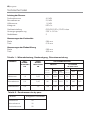
The adjustable connection is fixed to the
comprehensive ramp by means of a
threaded nut G 1/2". All the components
shown in the figure have already been
assembled in the factory.
The appliance, before leaving the factory, has
been tested in order to give you the best
results.
Important
When the final connection has been made, it
is essential that a thorough leak test is carried
out on the hob and installation. Use some
soapy water, never a flame.
A - Ramp with ending nut
B - Seal
C - Adjustable connection

12
progress
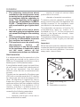
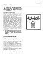
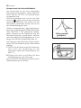
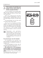
Adaptation to different types of gas
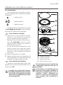
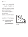
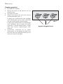
Injectors replacement
• Remove the pan supports.
• Remove the burner's caps and crowns.
• With a socket spanner 7 unscrew and
remove the injectors (Fig. 2), and replace
them with the ones required for the type
of gas in use.
• Reassemble the parts, following the
same procedure backwards.
• Replace the rating label (placed near the
gas supply pipe) with the relevant one for
the new type of gas supply. You can find
this label in the package of the injectors
supplied with the appliance.
Should the feeding gas pressure be different
or variable compared with the required
pressure, an appropriate pressure adjuster
must be fitted on the gas supply pipe, in
compliance with the rules in force.
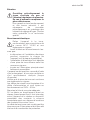
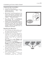
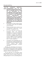
Adjustment of minimum level
To adjust the minimum level of the burners,
proceed as follows:
• Light the burner.
• Turn the knob on the minimum position.
• Remove the knob.
• With a thin screwdriver, adjust the by-
pass screw (Fig. 3). If changing from
natural gas to LPG, completely tighten
clockwise the screw, until a small regular
flame is obtained.
• If changing from LPG to natural gas
unscrew about 1/4 turn the by-pass
screw, until a small regular flame is
obtained.
• Finally check the flame does not go out
when quickly turning the knob from the
maximum position to the minimum
position.
This procedure can easily be carried out,
anyhow the hob has been positioned or built
in the working top.
Fig. 2
)
)
Bypass-screw
Fig. 3

progress 13
The appliance is designed to be
connected to 230 V monophase electricity
supply.
The connection must be carried out in
compliance with the laws and regulations in
force.
Before the appliance is connected:
1. check that the main fuse and the
domestic installation can support the
load (see the rating label);
2. check that the power supply is properly
earthed in compliance with the current
rules;
3. check the socket or the double pole
switch used for the electrical connection
can be easily reached with the appliance
built in the forniture unit.
The appliance is supplied with a connection
cable and the relevant plug.
The plug has to be fitted in a proper socket.
If connecting the appliance directly to the
electric system, it is necessary that you install
a double pole switch between the appliance
and the electricity supply, with a minimum
gap of 3 mm. between the switch contacts
and of a type suitable for the required load in
compliance with the current rules.
The connection cable has to be placed in
order that, in each part, it cannot reach a
temperature higher than 90°C.
The brown coloured phase cable (fitted in
the terminal block contact marked with "L")
must always be connected to the network
phase.
Electrical connection

14
progress
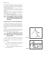
Remplacement of the voltage cable
The connection of the voltage cable to
the appliance's terminal block is of type "Y".
This means that its replacement requires the
specific equipment of a technician. In this
case, only cable type H05V2V2-F T90 must
be used. The cable section must be suitable
to the voltage and the working temperature.
The yellow/green earth wire must be
approximately 2 cm. longer than the phase
wires (Fig. 4-a).
To open the terminal block and reach the
terminals, proceed as follows:
z insert the point of a screwdriver into the
visible protrunding part of the terminal
block;
z exert a light pressure and lift (Fig. 4-b)
Fig. 4-b
Earth
(yellow/green))
Neutral
Fig. 4-a

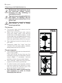
progress 15
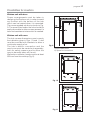
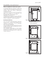
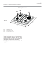
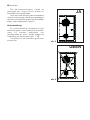
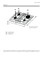
Building In
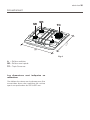
These hobs can be inserted in a built-in
kitchen unit whose depth is between 550
and 600 mm. The hobs dimensions are
shown in Fig. 5.
The cut out dimensions are shown in Fig. 6.
The edge of the cut out must have a
minimum distance from the rear wall of 55
mm.
If there are side walls, or sides of the
furniture unit near the hob, the cut out edges
must have a minimum distance of 100 mm.
Hanging forniture units or hoods must be
placed at 650 mm. minimum from the hob.
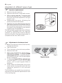
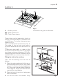
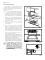
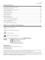
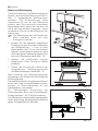
Fitting the hob to the worktop
Carry out the building in of the hob as
follows:
1. Place the seals supplied with the hob on
the front edge of the cut out. Then, place
them at 11 mm from the side edges and
at 10 mm from the rear edge, as shown
in the diagram, taking care that the seals
meet without overlapping.
2. Place the hob in the cut out, taking care
that it is centred.
3. Fix the hob with the relevant fixing
A = Auxiliary burner
SR = Semi-rapid burner
TC = Triple Crown burner
Fig. 6
Dimensions are given in millimeters
510
594
TC
SR
A
SR
Fig. 5

16
progress
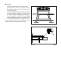
Fig. 7
Fig.8
a
a) seal
clamps, supplied with the injectors kit
(see diagram). When the fixing brackets
have been tightened, the excess seal
can be removed.
The overlaying sealing material should be
removed using a wooden or plastic knife
in order to avoid damaging the worktop.
To completely remove the sealing
material please position the plastic knife
at an angle (Position at an angle of 45°C).
The edge of the hob forms a double seal
which prevents the ingress of liquids.

progress 17
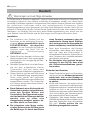
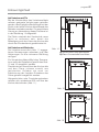
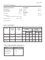
Possibilities for insertion
Kitchen unit with door
Proper arrangements must be taken in
designing the forniture unit, in order to avoid
any contact with the bottom of the hob
which can be heated when it is operated.
The recommended solution is shown in Fig.
9. The panel fitted under the hob should be
easily removable to allow an easy access if a
technical assistance intervention is needed.
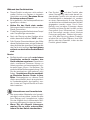
Kitchen unit with oven
The hob recess dimensions must comply
the indication given in Figs. 10 and 11 and
must be provided with brackets to allow a
continuous supply of air.
The hob's electric connection and the
oven's one must be carried out separately,
both for safety reasons and to allow the
oven to be easily taken off the unit.
Wall units or extractor hoods must be at least
650 mm from the cooktop (Fig. 6).
a) Removable panel
b) Space for connections
Fig. 9
Fig. 10
Fig. 11

18
progress
Before leaving the factory this appliance was
tested and verified by specialized personnel,
in order to ensure best performance. Any
repairs or intervention which may become
necessary, must be carried out with utmost
care and attention.
For this reason, this hob should only be
r
epaired or serviced by an authorised Service
Engineer and only genuine approved spare
parts should be used.
For Assistance, please contact your dealer
or an authorized Service Centre, specifying
the type of problem, the appliance model
(Mod.), the product number (Prod. No.) and
the serial number (Ser. No.). This information
is given on the dataplate which is supplied
in the accessories plastic bag.
Technical assistance and spare parts

electrolux 19
Les symboles suivants vous guideront tout au long de la lecture de votre notice:
Comment lire votre notice d'utilisation?
Avertissements importants ............................................................................................. 20
Utilisation de votre table de cuisson ............................................................................... 23
Conseils d'utilisation....................................................................................................... 25
Entretien et nettoyage .................................................................................................... 26
Caractéristiques techniques .......................................................................................... 28
Installation ...................................................................................................................... 29
Adaptation des brûleurs au gaz utilisé ............................................................................ 33
Encastrement ................................................................................................................. 35
Possibilités d'encastrement ............................................................................................ 37
Plaque signalétique ........................................................................................................ 38
Sommaire
Instructions de sécurité
Descriptions d'opérations
Conseils et recommandations
Informations sur l'environnement
Cet appareil est conforme aux Directives Communitaires CEE suivantes :
•
2006/95 (Basse Tension) ;
•
90/396 (Appareil Gaz)
•
89/336 (Compatibilité Electromagnétique) ;
•
93/68 (Directives Générales) et modifications successives.
Ces instructions sont valables uniquement pour les pays dont les symboles d'identification
figurent sur la couverture de cette notice d'utilisation et sur l'appareil lui-même.
Conservez cette notice d’utilisation avec votre appareil. Si l’appareil devait être vendu ou
cédé à une autre personne, assurez-vous que la notice d’utilisation l’accompagne. Le
nouvel utilisateur pourra alors être informé du fonctionnement de celui-ci et des avertisse-
ments s’y rapportant. Ces avertissements ont été rédigés pour votre sécurité et celle
d’autrui.
)
FABRICANT:
ELECTROLUX HOME PRODUCTS ITALY S.p.A.
Viale Bologna, 298
47100 FORLÌ (Italie)

20 electrolux
Utilisation
• Cet appareil a été conçu pour être utilisé
par des adultes. Veillez à ce que les
enfants n’y touchent pas et ne l’utilisent
pas comme un jouet.
• A la réception de l’appareil, déballez-le ou
faites-le déballer immédiatement. Vérifiez
son aspect général. Faites les éventuelles
réserves
par écrit sur le bon de livraison ou
sur le bon d’enlèvement dont vous
garderez un exemplaire.
• Votre appareil est destiné à un usage
domestique normal. Ne l’utilisez pas à des
fins commerciales ou industrielles ou pour
d’autres buts que celui pour lequel il a été
conçu.
• Ne modifiez pas ou n’essayez pas de
modifier les caractéristiques de cet
appareil. Cela représenterait un danger
pour vous.
• Avant d’utiliser votre appareil, assurez-
vous qu’il a été correctement raccordé
pour le type de gaz distribué.
• Cet appareil n'est pas destiné à être utilisé
par des enfants ou des personnes dont les
capacités physiques, sensorielles ou
mentales, ou le manque d'expérience et
de connaissance les empêchent d'utiliser
l'appareil sans risque lorsqu'ils sont sans
surveillance ou en l'absence d'instruction
d'une personne responsable qui puisse
leur assurer une utilisation de l'appareil
sans danger.
• Tenez les enfants à distance pendant le
fonctionnement : la table de cuisson et les
récipients s’échauffent et peuvent rester
chauds longtemps après l’arrêt de
l’appareil.
• Baissez ou éteignez toujours la flamme
d’un brûleur avant de retirer un récipient.
• N’utilisez jamais votre table à vide (sans
récipient dessus)
• Assurez-vous que les manettes sont
toujours en position arrêt «
z » lorsque
l’appareil n’est pas utilisé.
• N’utilisez pas de récipients instables ou
déformés : ils peuvent se renverser et
provoquer un accident.
• Les réparations ne doivent être effectuées
que par un service après vente qualifié.
Une réparation non conforme peut être la
cause de graves dommages.
• Ne conservez pas à proximité de l’appareil
des produits inflammables sensibles aux
températures (exemples: produits de
nettoyage, bombe aérosols, ..)
• Assurez-vous que les enfants ne manipu-
lent pas commandes.
• Ne laissez rien sur la table de cuisson. Une
mise en fonctionnement accidentelle
pourrait provoquer un incendie.
• Si vous utilisez un appareil électrique à
proximité de votre table de cuisson, veillez
a ce que le câble d’alimentation de cet
appareil électrique ne soit pas en contact
avec la surface chaude de la table.
• Surveillez attentivement la cuisson lors de
Avertissements importants
Cet appareil doit être installé par une personne qualifiée et selon les normes en vigueur.
Veuillez maintenant lire attentivement cette notice pour une utilisation optimale de votre
appareil.
Nous déclinons toute responsabilité en cas de dommages ou d’accident provoqués par
l’appareil du fait du non-respect de ces avertissements.
Fran
ç
ais
La page est en cours de chargement...
La page est en cours de chargement...
La page est en cours de chargement...
La page est en cours de chargement...
La page est en cours de chargement...
La page est en cours de chargement...
La page est en cours de chargement...
La page est en cours de chargement...
La page est en cours de chargement...
La page est en cours de chargement...
La page est en cours de chargement...
La page est en cours de chargement...
La page est en cours de chargement...
La page est en cours de chargement...
La page est en cours de chargement...
La page est en cours de chargement...
La page est en cours de chargement...
La page est en cours de chargement...
La page est en cours de chargement...
La page est en cours de chargement...
La page est en cours de chargement...
La page est en cours de chargement...
La page est en cours de chargement...
La page est en cours de chargement...
La page est en cours de chargement...
La page est en cours de chargement...
La page est en cours de chargement...
La page est en cours de chargement...
La page est en cours de chargement...
La page est en cours de chargement...
La page est en cours de chargement...
La page est en cours de chargement...
La page est en cours de chargement...
La page est en cours de chargement...
La page est en cours de chargement...
La page est en cours de chargement...
La page est en cours de chargement...
La page est en cours de chargement...
La page est en cours de chargement...
La page est en cours de chargement...
La page est en cours de chargement...
La page est en cours de chargement...
La page est en cours de chargement...
La page est en cours de chargement...
La page est en cours de chargement...
La page est en cours de chargement...
La page est en cours de chargement...
La page est en cours de chargement...
La page est en cours de chargement...
La page est en cours de chargement...
La page est en cours de chargement...
La page est en cours de chargement...
La page est en cours de chargement...
La page est en cours de chargement...
La page est en cours de chargement...
La page est en cours de chargement...
La page est en cours de chargement...
La page est en cours de chargement...
La page est en cours de chargement...
La page est en cours de chargement...
-
 1
1
-
 2
2
-
 3
3
-
 4
4
-
 5
5
-
 6
6
-
 7
7
-
 8
8
-
 9
9
-
 10
10
-
 11
11
-
 12
12
-
 13
13
-
 14
14
-
 15
15
-
 16
16
-
 17
17
-
 18
18
-
 19
19
-
 20
20
-
 21
21
-
 22
22
-
 23
23
-
 24
24
-
 25
25
-
 26
26
-
 27
27
-
 28
28
-
 29
29
-
 30
30
-
 31
31
-
 32
32
-
 33
33
-
 34
34
-
 35
35
-
 36
36
-
 37
37
-
 38
38
-
 39
39
-
 40
40
-
 41
41
-
 42
42
-
 43
43
-
 44
44
-
 45
45
-
 46
46
-
 47
47
-
 48
48
-
 49
49
-
 50
50
-
 51
51
-
 52
52
-
 53
53
-
 54
54
-
 55
55
-
 56
56
-
 57
57
-
 58
58
-
 59
59
-
 60
60
-
 61
61
-
 62
62
-
 63
63
-
 64
64
-
 65
65
-
 66
66
-
 67
67
-
 68
68
-
 69
69
-
 70
70
-
 71
71
-
 72
72
-
 73
73
-
 74
74
-
 75
75
-
 76
76
-
 77
77
-
 78
78
-
 79
79
-
 80
80


Progress PAG7530E-B Manuel utilisateur
- Taper
- Manuel utilisateur
- Ce manuel convient également à
dans d''autres langues
- English: Progress PAG7530E-B User manual
- Deutsch: Progress PAG7530E-B Benutzerhandbuch
- Nederlands: Progress PAG7530E-B Handleiding
Autres documents
-
ZANKER ZKF780ITXB Manuel utilisateur
-
-
Zanussi PI44GC/2 Manuel utilisateur
-
-
Aeg-Electrolux 79550G-M Manuel utilisateur
-
Bauknecht AKZ 502 IX Guide d'installation
-
Caterchef 680015 Manuel utilisateur
-
RM BRM-780 E/N Instructions For Installation And Use Manual