
sauder.com
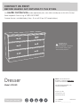
Dresser
Model 420449
NOTE: THIS INSTRUCTION
BOOKLET CONTAINS IMPORTANT
SAFETY INFORMATION.
PLEASE READ AND KEEP FOR
FUTURE REFERENCE.
English pg 1-20
Français pg 21-24
Español pg 25-28
Lot # 527089 03/22/19
Purchased: __________________
sauder.com
CONTACT US FIRST
BEFORE MAKING ANY RETURNS TO THE STORE.
Share your journey!
sauder.com
CONTACT US FIRST
BEFORE MAKING ANY RETURNS TO THE STORE.
Visit sauder.com/service to order replacement parts, view video assembly tips, or chat with a live rep.
Prefer the phone? Give us a ring at
1-800-523-3987.
Customer Service is available Monday-Friday - 9 a.m. to 5:30 p.m. EST (except holidays)
WARNING
CHOKING HAZARD - Small Parts
Not for children under 3 years.
Adult assembly required.

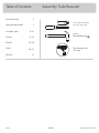
Table of Contents Assembly Tools Required
3
4
5-20
21-24
25-28
29-20
31
Part Identifi cation
Hardware Identifi cation
Assembly Steps
Français
Español
Safety
Warranty
Hammer
Not actual size
No. 2 Phillips Screwdriver
Tip Shown Actual Size
Skip the power trip.
This time.
420449 www.sauder.com/servicePage 2

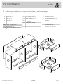
Part Identifi cation
å While not all parts are labeled, some of the parts will have a label or an inked letter on the edge
to help distinguish similar parts from each other. Use this part identifi cation to help identify similar parts.
A RIGHT END (1)
B LEFT END (1)
C UPRIGHT (1)
D TOP (1)
D166 SMALL DRAWER BACK (2)
D167 DRAWER BACK (4)
D245 SMALL RIGHT DRAWER SIDE (2)
D257 LEFT DRAWER SIDE (4)
D262 RIGHT DRAWER SIDE (4)
D271
SMALL LEFT DRAWER SIDE (2)
- 1 with label
D703 DRAWER BOTTOM (6)
E BASE (1)
F BRACE (4)
G DRAWER FRONT (4)
H SMALL DRAWER FRONT (2)
I BACK (1)
J TOP MOLDING (1)
M64
DRAWER BRACE (6)
(Hidden part using recycled
material. Color may vary.)
Now you know
our ABCs.
420449www.sauder.com/service
Page 3
A
B
C
D
E
F
G
H
I
J
D245
M64
D271
D703
D166
D262
M64
D257
D703
D167
F
F
F

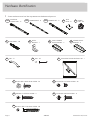
Hardware Identifi cation
å Screws are shown actual size. You may receive extra hardware with your unit.
SMALL DRAWER
FRONT BRACKET - 2
8G
DRAWER FRONT
BRACKET - 4
9G
35AA
UNIVERSAL
CABINET RAIL - 12
35AC
DRAWER RIGHT - 6
35AD
DRAWER LEFT - 6
TACK
GLIDE - 6
13E
HIDDEN
CAM - 20
1F
CAM DOWEL - 20
2F
METAL
BRACKET - 7
4G
NAIL - 45
1N
BLACK 9/16" LARGE HEAD SCREW - 38
1S 3S
GOLD 5/16" FLAT HEAD SCREW - 48
12S
BROWN 1" FLAT HEAD SCREW - 4
15S
SILVER 5/8" MACHINE SCREW - 12
30S
BLACK 1-9/16" FLAT HEAD SCREW - 30
PULL - 6
2K
420449 www.sauder.com/servicePage 4
FURNITURE TIPPING RESTRAINT KIT - 1
97

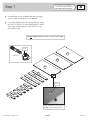
Step 1
Look for this icon. It means a
video assembly tip is available at
www.sauder.com/service/tips
å
Assemble your unit on a carpeted fl oor or on the empty
carton to avoid scratching your unit or the fl oor.
å
Push twenty HIDDEN CAMS (1F) into the ENDS (A and B),
UPRIGHT (C), BRACES (F), and DRAWER BRACES (M64).
Then, insert the metal end of a CAM DOWEL (2F) into
each HIDDEN CAM.
420449www.sauder.com/service
Page 5
Insert the metal end of the CAM
DOWEL into the HIDDEN CAM.
Arrow
(20 used)
Arrow
1F
2F
Do not tighten the HIDDEN CAMS in this step.
F
M64
A
B
C
F
F
F
M64
M64
M64
M64
M64

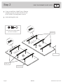
Step 2
å
Fasten six UNIVERSAL CABINET RAILS* (35AA) to
the ENDS (A and B). Use twelve GOLD 5/16" FLAT
HEAD SCREWS (3S) through holes #1 and #3.
å
*patent pending glide system
420449 www.sauder.com/servicePage 6
GOLD 5/16" FLAT HEAD SCREW
(12 used for the RAILS)
3S
3
2
1
1
2
3
VIEW THE DRAWER GLIDE VIDEO
A
Surface with
HIDDEN CAMS
B
Surface with
HIDDEN CAMS
Finished edge
Glide end
3
2
1
3
2
1
1
2
3
1
2
3
Glide end
Finished edge

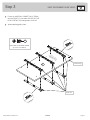
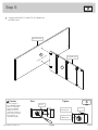
å
Fasten six UNIVERSAL CABINET RAILS* (35AA)
to the UPRIGHT (C). Use twelve GOLD 5/16" FLAT
HEAD SCREWS (3S) through holes #1 and #3.
å
*patent pending glide system
Step 3
420449www.sauder.com/service
Page 7
C
GOLD 5/16" FLAT HEAD SCREW
(12 used for the RAILS)
3S
Surface with
HIDDEN CAMS
Glide end
1
2
3
1
2
1
2
1
2
3
1
2
3
1
2
3
Finished edge
VIEW THE DRAWER GLIDE VIDEO

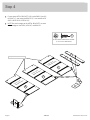
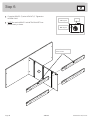
Step 4
å
Fasten seven METAL BRACKETS (4G) to the ENDS (A and B),
UPRIGHT (C), and two of the BRACES (F). Use seven BLACK
9/16" LARGE HEAD SCREWS (1S).
å
NOTE: Be sure the edges of the METAL BRACKETS are even
with the edges of the ENDS, UPRIGHT, and BRACES.
420449 www.sauder.com/servicePage 8
A
C
B
F
F
BLACK 9/16" LARGE HEAD SCREW
(7 used for the BRACKETS)
1S
Surface with
HIDDEN CAMS
Surface with
HIDDEN CAMS
Surface with
HIDDEN CAMS
4G
4G
Edge with CAM DOWELS

å
Fasten the UPRIGHT (C) to the TOP (D). Tighten two
HIDDEN CAMS.
Step 5
420449www.sauder.com/service
Page 9
Start Tighten
Arrow
Minimum
190 degrees
Caution
Risk of damage or
injury. HIDDEN CAMS
must be completely
tightened. HIDDEN
CAMS that are not
completely tightened
may loosen, and parts
may separate. To
completely tighten:
Arrow
Maximum
210 degrees
C
Surface with holes
D
Finished edge
Rounded edge

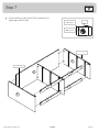
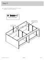
Step 6
å
Fasten the BRACES (F) to the UPRIGHT (C). Tighten four
HIDDEN CAMS.
å
NOTE: Be sure the BRACES with METAL BRACKETS are
placed exactly as shown.
420449 www.sauder.com/servicePage 10
F
C
Surface with HIDDEN CAMS
F
Surface with HIDDEN CAMS
F
Surface with HIDDEN CAMS
F
Surface with HIDDEN CAMS
The METAL BRACKET
must be here.
Arrow
Minimum
190 degrees
Maximum
210 degrees

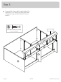
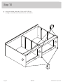
å
Fasten the ENDS (A and B) to the TOP (D) and BRACES (F).
Tighten eight HIDDEN CAMS.
Step 7
420449www.sauder.com/service
Page 11
Arrow
Minimum
190 degrees
Maximum
210 degrees
Finished edge
Finished edge
D
F
F
F
F
A
B

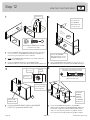
Step 8
å
Fasten the BASE (E) to the ENDS (A and B), UPRIGHT (C),
and BRACES (F). Use seven BLACK 9/16" LARGE HEAD
SCREWS (1S) through the METAL BRACKETS and into
the BASE.
420449 www.sauder.com/servicePage 12
F
F
A
B
C
E
BLACK 9/16" LARGE HEAD SCREW
(7 used for the BASE)
1S
Rounded edge
Surface without holes

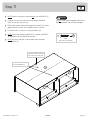
å
Fasten the TOP MOLDING (J) to the TOP (D). Use four
BROWN 1" FLAT HEAD SCREWS (12S).
Step 9
420449www.sauder.com/service
Page 13
Rounded edge
BROWN 1" FLAT HEAD SCREW
(4 used for the MOLDING)
12S
Finished surface
J
D

Step 10
å
Using your hammer, gently tap six TACK GLIDES (13E) into
the edges of the ENDS (A and B), UPRIGHT (C), and BASE (E).
420449 www.sauder.com/servicePage 14
13E
13E
A
B
C
E
F
F

Step 11
420449www.sauder.com/service
Page 15
å
NOTE: When turning your unit over, do not lift on the BRACES (F).
å
Carefully turn your unit over onto its front edges. Unfold the
BACK (I) and lay it over your unit.
å
Make equal margins along all four edges of the BACK (I). Push on
opposite corners of your unit if needed to make it "square".
å
Fasten the BACK (I) to your unit using the NAILS (1N).
å
NOTE: When nailing along the BRACES (F), support the BRACES
to keep them even with the BACK and solid.
å
NOTE: Be sure to tap NAILS into the holes that line up over
the UPRIGHT (C).
Do not stand the unit upright without the
BACK fastened. The unit may collapse.
Caution
These holes must line up
over the UPRIGHT (C).
NAIL
(45 used for the BACK)
1N
I
F
F
This perforated hole needs
to be at the top of the unit.

Step 12
420449 www.sauder.com/servicePage 16
VIEW THE T-SLOT BOX VIDEO
1
3
2
4
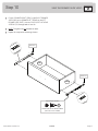
å
Pull the DRAWER FRONT BRACKETS (9G) apart and slide them
into the grooves in the DRAWER SIDES (D257 and D262). You
may need to gently tap them in with a hammer.
å
NOTE: The DRAWER FRONT BRACKETS are marked "RH" and
"LH" for easy identifi cation.
å
Fasten the DRAWER FRONT (G) to the DRAWER FRONT
BRACKETS (9G). Use four BLACK 9/16" LARGE HEAD SCREWS (1S).
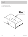
å
Slide the DRAWER BOTTOM (D703) into the grooves in the
DRAWER SIDES (D257 and D262) and DRAWER FRONT (G).
å
Fasten the DRAWER BRACE (M64) to the DRAWER
FRONT (G). Tighten one HIDDEN CAM.
å
Fasten the DRAWER BACK (D167) to the DRAWER
SIDES (D257 and D262) and DRAWER BRACE (M64). Use
fi ve BLACK 1-9/16" FLAT HEAD SCREWS (30S). Repeat
Step 12 for the remaining drawers. The SMALL drawers
will use parts 8G, H, D166, D245, D271, D703, and M64.
BLACK 9/16" LARGE HEAD SCREW
(24 used in this step)
1S
D262
D703
D257
D262
D167
D257
D262
D257
G
G
Be sure the DRAWER
BOTTOM inserts into the
DRAWER FRONT groove.
Be sure the
DRAWER
BOTTOM
inserts into
the DRAWER
BACK groove.
With the palm of
your hand, tap
the DRAWER
BOTTOM down
into the groove.
30S
Start each screw a few turns before
completely tightening any of them.
BLACK 1-9/16" FLAT HEAD SCREW
(30 used in this step)
Arrow
Maximum
210 degrees
Minimum
190 degrees
Push down
G
M64
M64
Surface with
HIDDEN CAM
9G
Unfi nished
surface
Hidden part using
recycled material.
Color may vary.

å
Fasten a DRAWER RIGHT (35AC) to the RIGHT DRAWER
SIDE (D262) and a DRAWER LEFT (35AD) to the LEFT
DRAWER SIDE (D257). Use four GOLD 5/16" FLAT HEAD
SCREWS (3S) through holes #1 and #2.
å
NOTE: The glides are not intended to rotate.
å
Repeat this step for the remaining drawers.
Step 13
420449www.sauder.com/service
Page 17
1
2
1
2
VIEW THE DRAWER GLIDE VIDEO
Glide end
Glide end
D257
D262
GOLD 5/16" FLAT HEAD SCREW
(24 used for the SLIDES)
3S
(4 screws per drawer)

Step 14
å
Fasten a PULL (2K) to the DRAWER FRONT (G). Use two
SILVER 5/8" MACHINE SCREWS (15S).
å
Repeat this step for the remaining drawers.
420449 www.sauder.com/servicePage 18
G
2K
SILVER 5/8" MACHINE SCREW
(12 used for the PULLS)
15S

Step 15
420449www.sauder.com/service
Page 19
BLACK 9/16" LARGE HEAD SCREW
(1 used for the SAFETY STRAP)
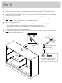
å
Carefully stand your unit upright in its fi nal location. We recommend using the SAFETY STRAP for added stability.
å
Open the FURNITURE TIPPING RESTRAINT KIT (97) and fasten the SAFETY STRAP to the TOP (D). Use the provided
BLACK 9/16" LARGE HEAD SCREW.
å
Carefully cut out the perforated hole in the BACK (I). Insert the other end of the SAFETY STRAP through this hole.
å
NOTE: Do not turn the SAFETY DRYWALL ANCHOR into a wall stud. If you prefer to fasten the SAFETY
STRAP to a wall stud, go to your local hardware store for proper hardware.
å
INSTALLATION INSTRUCTIONS:
1. Insert the SAFETY DRYWALL ANCHOR through the WASHER and one end of the SAFETY STRAP.
2. Using a Phillips screwdriver or a hand drill, press the screw slightly onto the drywall.
3. Apply pressure; turn the screw until a pilot hole is made and the nylon sheath slips through.
4. Turn the screw until it is fl ush against the wall and you feel a fi rm resistance.
5. Continue to turn until the screw starts spinning freely.
å
NOTE: Before moving your unit to a di erent location, unscrew the SAFETY DRYWALL ANCHOR from your wall. The
nylon sheath will remain behind your wall.
I
97
Safety
drywall
anchor
Safety strap
Washer
D

W
ARNING
AVER
TISSEMENT
ADVERTENCIA
o
c
c
u
r f
ro
m
f
u
r
n
it
u
r
e
tip
-
over. To h
e
lp
p
re
v
e
n
t tip
-
ove
r:
•
In
s
tal
l t
ip
-
ove
r
re
s
tra
in
t
p
r
ov
id
e
d.
•
P
la
c
e
h
e
a
v
ie
st ite
m
s
in
th
e
lo
w
e
r
d
rawers.
• Do not set TV’s or other heavy objects on
top of this product, unless the product is
d
r
a
we
r
s
, d
o
o
r
s
,
o
r s
h
e
lv
e
s.
•
N
e
ve
r
o
p
e
n
m
o
re
t
h
a
n
o
n
e
d
r
a
w
e
r
a
t a
tim
e.
U
s
e
o
f
t
ip
-
ov
e
r re
s
tra
in
t
s
m
a
y
o
n
ly
r
e
d
u
c
e, b
u
t
n
o
t
e
lim
in
a
te
, t
h
e
ris
k
o
f t
ip
-
o
v
er
.
T
h
is
is
a
p
e
rm
a
n
e
n
t
la
b
e
l.
D
o
n
o
t
re
m
ove
!
é
c
ra
s
e
m
e
n
t p
e
u
v
e
n
t s
u
r
v
e
n
ir s
i le
m
o
b
ilie
r
b
a
s
c
u
l
e. P
o
u
r p
ré
v
e
n
ir
le
b
a
s
c
u
le
m
e
n
t
:
•
In
s
ta
lle
r le
d
isp
o
s
it
if a
n
ti-
b
a
s
c
u
le
m
e
n
t
fo
u
r
n
i.
•
P
la
c
e
r
le
s a
rtic
le
s
p
lu
s
lo
u
rd
s
d
a
n
s
le
s
t
iro
irs
in
f
é
r
ie
u
r
s.
•
N
e
p
a
s
m
e
tt
re
d
e
t
é
lé
v
is
e
u
r o
u
d’a
u
tr
e
o
b
je
ts
lo
u
rd
s
s
u
r
le
d
e
s
s
u
s
d
e
c
e
m
e
u
ble, sa
u
f
s
i le
•
N
e
ja
m
a
is
o
u
v
rir p
lu
s
d’u
n
tir
o
ir à
la
fo
i
s
.
L
’u
ti
li
s
a
t
io
n
d
e
d
is
p
o
s
itifs
a
n
t
i-
b
a
s
c
u
le
m
e
n
t
p
e
u
t
r
é
d
u
ire
le
ris
q
u
e
d
e
b
a
s
c
u
le
m
en
t
, m
a
is
p
a
s
l’é
lim
in
e
r
.
C
e
tte
é
t
iq
u
e
tt
e
e
s
t
p
e
rm
a
n
e
n
t
e. N
e
p
a
s
l’e
n
lev
e
r!
p
u
e
d
e
n
o
c
u
rrir p
o
r e
l v
o
lca
r
d
e
lo
s
m
u
e
ble
s.
Pa
r
a
a
y
u
d
a
r a
p
r
e
v
e
n
ir q
u
e
s
e
v
o
lq
u
é
:
•
In
s
ta
la
r
l
a
c
o
n
te
n
c
ió
n
b
rin
d
a
d
a
p
a
r
a
e
v
ita
r
q
u
e
s
e v
o
lq
u
é.
•
C
o
lo
q
u
e
lo
s
a
rtíc
u
lo
s
m
á
s
p
e
s
a
d
o
s
e
n
lo
s
c
a
jo
n
e
s
in
f
e
r
io
r
e
s.
•
N
o
c
o
lo
q
u
e
te
le
v
is
o
re
s
u
o
tro
s
o
b
je
to
s
p
e
s
a
d
o
s
e
n
la
p
a
rt
e s
u
p
e
rio
r d
e
e
s
te
p
r
o
d
u
c
t
o
,
d
is
e
ñ
a
d
o
p
ar
a
a
co
m
o
d
a
r
lo
s.
•
N
u
n
c
a
p
e
r
m
ita
q
u
e
lo
s
n
iñ
o
s
s
e
s
u
b
a
n
o
s
e
•
N
u
n
c
a
a
b
ra
m
á
s
d
e
u
n
ca
j
ó
n
a
la
v
e
z
.
E
l u
s
o
d
e
la
c
o
n
te
n
c
ió
n
p
u
e
d
e
s
o
la
m
e
n
te
E
s
ta
e
s
u
n
a
e
t
iq
u
e
ta
p
e
r
m
a
n
e
n
t
e. ¡N
o
re
m
ov
e
r!
Step 16
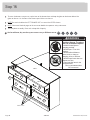
å
To insert the drawers into your unit, tip the front of the drawer down and drop the glides on the drawer behind the
glides on the unit. Lift the front of the drawer up and slide it into the unit.
å
NOTE: Be sure the label on the LEFT DRAWER SIDE is in one of the UPPER drawers.
å
NOTE: Please read the back pages of the instruction booklet for important safety information.
å
This completes assembly. Clean with a damp cloth. Wipe dry.
420449 www.sauder.com/servicePage 20
40 lbs.
20 lbs.
20 lbs.
35 lbs. each
G
G
G
H
H
G
WARNING
Children have died from
furniture tipover. To reduce
the risk of furniture tipover:
• ALWAYS install tipover
restraint provided.
• NEVER put a TV on this
product.
• NEVER allow children to
stand, climb, or hang on
drawers, doors, or shelves.
• NEVER open more than one
drawer at a time.
• Place heaviest items in the
lowest drawers.
This is a permanent label.
Do not remove!
1/19 526119
And to celebrate, why not share your success story at Walmart.com or
La page est en cours de chargement...
La page est en cours de chargement...
La page est en cours de chargement...
La page est en cours de chargement...
La page est en cours de chargement...
La page est en cours de chargement...
La page est en cours de chargement...
La page est en cours de chargement...
La page est en cours de chargement...
La page est en cours de chargement...
La page est en cours de chargement...
La page est en cours de chargement...
-
 1
1
-
 2
2
-
 3
3
-
 4
4
-
 5
5
-
 6
6
-
 7
7
-
 8
8
-
 9
9
-
 10
10
-
 11
11
-
 12
12
-
 13
13
-
 14
14
-
 15
15
-
 16
16
-
 17
17
-
 18
18
-
 19
19
-
 20
20
-
 21
21
-
 22
22
-
 23
23
-
 24
24
-
 25
25
-
 26
26
-
 27
27
-
 28
28
-
 29
29
-
 30
30
-
 31
31
-
 32
32


dans d''autres langues
- English: Sauder 420449 Operating instructions
- español: Sauder 420449 Instrucciones de operación
Documents connexes
-
Sauder 414291 Guide d'installation
-
-
-
-
-
-
-
-
-
