
TWECO
®
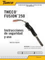
FUSION
™
250
Safety and
Operating
Instructions
AIR-COOLED MIG GUN 250 AMP
Tweco.com
English
Canadien Français
Americas Español
Revision: B Issue Date: August 2, 2013 Manual No.: 89200015
IMPORTANT: Included inside - special
instructions for liner replacement.

WE APPRECIATE YOUR BUSINESS!
Congratulations on receiving your new Tweco product. We are proud to
have you as our customer and will strive to provide you with the best
service and support in the industry. This product is backed by our extensive
warranty and world-wide service network.
We know you take pride in your work and we feel privileged to provide you
with this high performance product that will help you get the job done.
For more than 75 years Tweco has provided quality products you can trust,
when your reputation is on the line.
YOU ARE IN GOOD COMPANY!
Tweco is a Global Brand of Arc Welding Products for Victor Technologies
Inc. We distinguish ourselves from our competition through market-
leading innovation and truly dependable products that will stand the test of
time.
We strive to enhance your productivity, efficiency and welding performance
enabling you to excel in your craft. We design products with the welder in
mind delivering- advanced features, durability, ease of use and ergonomic
comfort.
Above all, we are committed to a safer working environment within the
welding industry. Your satisfaction with this product and its safe operation
is our ultimate concern. Please take the time to read the entire manual,
especially the Safety Precautions.
If you have any questions or concerns regarding your new Tweco product,
please contact our friendly and knowledgeable Customer Service Team at:
1-800-462-2782 (USA) and 1-905-827-4515 (Canada),
or visit us on the web at www.Tweco.com

i
WARNINGS
Read and understand this entire Manual and your employer’s safety practices
before installing, operating, or servicing the equipment. While the information
contained in this Manual represents the Manufacturer’s judgment, the Manufacturer
assumes no liability for its use.
Tweco
®
Fusion 250 AMP MIG Gun
Safety and Operating Instructions
Instruction Guide Number 89200015
Published by:
Victor Technologies, Inc.
2800 Airport Rd.
Denton, TX. 76208
(940) 566-2000
www.tweco.com
U.S. Customer Care: (800) 426-1888
Canada Customer Care: 905-827-4515
International Customer Care: (940) 381-1212
Copyright © 2012, 2013 Victor Technologies, Inc. All rights reserved.
Reproduction of this work, in whole or in part, without written permission of the publisher is
prohibited.
The publisher does not assume and hereby disclaims any liability to any party for any loss
or damage caused by any error or omission in this Manual, whether such error results from
negligence, accident, or any other cause.
Publication Date: December 17, 2012
Revision Date: August 2, 2013
Record the following information for Warranty purposes:
Where Purchased:
Purchase Date:
Equipment Serial #:

ii
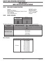
Table of Contents
SECTION 1: SAFETY PRECAUTIONS .........................................................................3
1.01 Safety Precautions .......................................................................... 3
SECTION 2: INTRODUCTION ......................................................................................5
2.01 How to Use this Manual ................................................................... 5
2.02 Receipt of Equipment ....................................................................... 5
2.03 Description ....................................................................................... 5
SECTION 3: MIG GUN SPECIFICATIONS.....................................................................6
3.01 MIG Gun Classification ..................................................................... 6
3.02 Duty Cycles ..................................................................................... 6
3.03 Tweco
®
fusion 250A MIG Gun Selection guide ................................ 7
3.04 Tweco
®
Fusion 250A MIG Gun Part Number Identification .............. 7
3.05 Velocity Contact Tip Nozzle Identification ......................................... 8
3.06 Velocity 250 Amp Conductor Tube Identification ............................. 8
SECTION 4: MIG GUN INSTALLATION ........................................................................9
4.01 Direct Plug MIG Gun Installation ...................................................... 9
4.02 Tweco
®
MIG-Kwik Connection and Adapter Kit Installation ........... 10
SECTION 5: REPLACEMENT INSTRUCTIONS ...........................................................11
5.01 Replacing Velocity Contact Tip ...................................................... 11
5.02 Replace Conductor Tube ............................................................... 11
5.03 Conduit Identification and Replacement ......................................... 12
5.04 Replacing Handle, trigger .............................................................. 13
SECTION 6: CABLEHOZ
®
REPAIR ............................................................................14
6.01 Tools Required ...............................................................................14
6.02 Repair of Cablehoz
®
...................................................................... 14
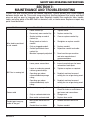
SECTION 7: MAINTENANCE AND TROUBLESHOOTING............................................19
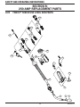
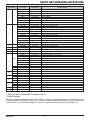
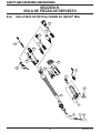
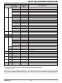
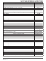
SECTION 8: 250 AMP REPLACEMENT PARTS .........................................................20
8.02 Tweco
®
Fusion 250 A MIG Gun Parts ............................................ 20
8.02 Tweco
®
Fusion MIG Gun Consumables ......................................... 22
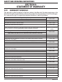
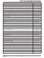
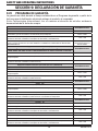
SECTION 9: STATEMENT OF WARRANTY ................................................................24
9.01 Warranty Schedule .........................................................................24
Global Contact Information ...............................................Rear Cover

SAFETY AND OPERATING INSTRUCTIONS
389200015
SECTION 1:
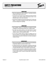
SAFETY PRECAUTIONS
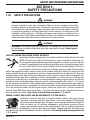
1.01 SAFETY PRECAUTIONS
WARNING
SERIOUS INJURY OR DEATH may result if welding and cutting equipment is not
properly installed, used, and maintained. Misuse of this equipment and other
unsafe practices can be hazardous. The operator, supervisor, and helper must read
and understand the following safety warnings and instructions before installing
or using any welding or cutting equipment, and be aware of the dangers of the
welding or cutting process. Training and proper supervision are important for a
safe work place. Keep these instructions for future use. Additional recommended
safety and operating information is referenced in each section.
WARNING
WARNING: This product contains chemicals, including lead, known to the State
of California to cause birth defects and other reproductive harm. Wash hands
after handling.
ELECTRIC SHOCK CAN CAUSE INJURY OR DEATH
Install and maintain equipment in accordance with the National Electrical Code
(NFPA 70) and local codes. Do not service or repair equipment with power on.
Do not operate equipment with protective insulators or covers removed. Service
or repair to equipment must be done by qualified and/or trained personnel only.
Do not contact electrically live parts. Always wear dry welding gloves that are in
good condition. Aluminized, protective clothing can become part of the electrical
path. Keep oxygen cylinders, chains, wires, ropes, cranes, and hoists away from any part of the
electrical path. All ground connections must be checked periodically to determine if they are
mechanically strong, and electrically adequate for the required current. When engaged in AC
welding/cutting under wet conditions or where perspiration is a factor, the use of automatic
controls for reducing the no load voltage is recommended to reduce shock hazards. Accidental
contact must be prevented when using open circuit voltage exceeding 80 volts AC, or 100 volts
DC by adequate insulation or other means. When welding is to be suspended for any length of
time, such as during lunch or overnight, all electrode holders and electrodes should be removed
from the electrode holder and the power supply should be turned off to prevent accidental
contact. Keep MIG Guns, electrode holders, Tig torches, Plasma torches, and electrodes away
from moisture and water. See safety and operating references 1, 2, and 8.
SMOKE, FUMES, AND GASES CAN BE DANGEROUS TO YOUR HEALTH
Ventilation must be adequate to remove smoke, fumes, and gases during
operation to protect operators and others in the area. Vapors of chlorinated
solvents can form the toxic gas “Phosgene” when exposed to ultraviolet radiation
from an electric arc. All solvents, degreasers, and potential sources of these
vapors must be removed from the operating area. Use air-supplied respirators
if ventilation is not adequate to remove all fumes and gases. Oxygen supports, and vigorously
accelerates fire and should never be used for ventilation. See safety and operating references
1, 2, 3, and 4.

4
SAFETY AND OPERATING INSTRUCTIONS
89200015
ARC RAYS, HOT SLAG, AND SPARKS CAN INJURE EYES AND BURN SKIN
Welding and cutting processes produce extreme localized heat and strong
ultraviolet rays. Never attempt to weld/cut without a federally compliant welding
helmet with the proper lens. A number 12 to 14 shade filter lens provides the
best protection against arc radiation. When in a confined area, prevent the
reflected arc rays from entering around the helmet. Approved shielding curtains
and appropriate goggles should be used to provide protection to others in the surrounding area.
Skin should be protected from arc rays, heat, and molten metal. Always wear protective gloves
and clothing. All pockets should be closed and cuffs sewn shut. Leather aprons, sleeves, leggings,
etc. should be worn for out-of-position welding and cutting, or for heavy operations using large
electrodes. Hightop work shoes provide adequate protection from foot burns. For added protection,
use leather spats. Flammable hair preparations should not be used when welding/cutting. Wear
ear plugs to protect ears from sparks. Where work permits, the operator should be enclosed in
an individual booth painted with a low reflective material such as zinc oxide.
See safety and operating references 1, 2, and 3.
WELDING SPARKS CAN CAUSE FIRES AND EXPLOSIONS
Combustibles reached by the arc, flame, flying sparks, hot slag, and heated
materials can cause fire and explosions. Remove combustibles from the work
area and/or provide a fire watch. Avoid oily or greasy clothing as a spark may
ignite them. Have a fire extinguisher nearby, and know how to use it. If welding/
cutting is to be done on a metal wall, partition, ceiling, or roof, precautions must
be taken to prevent ignition of nearby combustibles on the other side. Do not
weld/cut containers that have held combustibles. All hollow spaces, cavities, and containers
should be vented prior to welding/cutting to permit the escape of air or gases. Purging with inert
gas is recommended. Never use oxygen in a welding torch. Use only inert gases or inert gas
mixes as required by the process. Use of combustible compressed gases can cause explosions
resulting in personal injury or death. Arcing against any compressed gas cylinder can cause
cylinder damage or explosion. See safety and operating references 1, 2, 5, 7, and 8.
NOISE CAN DAMAGE HEARING
Noise from the air carbon-arc process can damage your hearing. Wear protective
hearing devices to ensure protection when noise levels exceed OHSA standards.
Adequate hearing protection devices must be worn by operators and surrounding
personnel to ensure personal protection against noise. See safety and operating
references 1, 2, and 6.
SAFETY AND OPERATING REFERENCES
1. Code of Federal Regulations (OSHA) Section 29, Part 1910.95, 132, 133, 134, 139,
251, 252, 253, 254 and 1000. U.S. Government Printing Office, Washington, DC 20402.
2. ANSI Z49.1 “Safety in Welding and Cutting”.
3. ANSI Z87.1 “Practice for Occupational and Educational Eye and Face Protection”.
4. ANSI Z88.2. “Standard Practice for Respiratory Protection”. American National
Standards Institute, 1430 Broadway, New York, NY 10018.
5. AWS F4.1. “Recommended Safe Practices for Welding and Cutting Containers”.
6. AWS C5.3. “Recommended Practices for Air Carbon-Arc Gouging and Cutting”. The
American Welding Society, 550 NW Lejeune Rd., P.O. Box 351040, Miami, FL 33135.
7. NFPA 51B. “Fire Prevention in Cutting and Welding Processes”.
8. NFPA-7. “National Electrical Code”. National Fire Protection Association, Battery Park,
Quincy, MA 02269.
9. CSA W117.2. “Safety in Welding, Cutting and Allied Processes”. Canadian Standards
Association, 178 Rexdale Blvd., Rexdale, Ontario, Canada M9W 1R3.

SAFETY AND OPERATING INSTRUCTIONS
589200015
SECTION 2:
INTRODUCTION
2.01 HOW TO USE THIS MANUAL
To ensure safe operation, read the entire manual, including the chapters on safety instructions
and warnings.
Throughout this manual, the words WARNING, CAUTION, and NOTE may appear. Pay particular
attention to the information provided under these headings. These special annotations are
easily recognized as follows:
NOTE
NOTE conveys installation, operation, or maintenance information which is
important but not hazard-related.
CAUTION
CAUTION indicates a potentially hazardous situation which, if not avoided, may
result in injury.
WARNING
WARNING indicates a potentially hazardous situation which, if not avoided, could
result in death or serious injury.
2.02 RECEIPT OF EQUIPMENT
When you receive the equipment, check it against the invoice to make sure it is complete and
inspect the equipment for possible damage due to shipping. If there is any damage, notify the
carrier immediately to file a claim. Furnish complete information concerning damage claims
or shipping errors to the location in your area, listed on the back cover of this manual. Include
a full description of the parts in error.
If you want additional or replacement copies of this manual, please contact Tweco
®
at the
address and phone number in your area listed on the back cover of this manual. Include the
Manual number (from page i).
2.03 DESCRIPTION
Tweco MIG Guns are furnished with rear connections to fit directly into most Miller
®
, Lincoln
®
,
and Euro connection wire feeders. These guns are referred to as Direct Plug MIG Guns. Tweco
MIG guns are also furnished with the time-proven MIG-Kwik connection. The MIG-Kwik
connection, when utilized with a Tweco adapter kit, allows a Tweco MIG gun to be installed on
almost any wire feed system. For a listing of available adapter kits, see the Tweco Adapter Kit
Listing, Form No. TAKL-97, or call Tweco Customer Care.
MILLER is a registered trademark of Miller Electric Mfg. Co.; ESAB is a registered trademark of ESAB AB; LINCOLN is
a registered trademark of LINCOLN Electric Co.; The aforementioned registered trademarks are no way affiliated with
Tweco Products, Inc. or Victor Technologies, Inc. Tweco is a registered trademark of Victor Technologies, Inc.

6
SAFETY AND OPERATING INSTRUCTIONS
89200015
SECTION 3:
MIG GUN SPECIFICATIONS
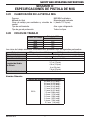
3.01 MIG GUN CLASSIFICATION
Process MIG/MAG welding
Method of Guidance Manually guided
Voltage Class for Welding and Control Circuits L (up to 113 V peak)
Type of Cooling Air or cooling gas
Type of Shielding Gas All types
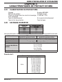
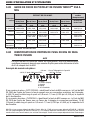
3.02 DUTY CYCLES
Duty Cycle
MIG Gun
250 AMP
10% 320
35% 290
80% 250
100% 195
The above duty cycles were established by testing under the following parameters:
Parameter MIG (metal inert gas) MAG (metal active gas)
Type of Voltage D.C.
Shielding Gas Argon Argon/CO
2
Mixed Gas (80/20, 75/25)
Gas Flow Rate 30-35 CFH (14,2- 16,5 l/m)
Gun Cable Length
10 ft. (3 m)
12 ft. (3,7 m)
15 ft. (4,6 m)
20 ft. (6 m)
25 ft. (7,6 m)
Electrode Polarity Positive
Wire Diameter
Wire (Continuous Electrode) Size
250 amp
.023" (0,6 mm)
.030" (0,8 mm)
.035" (0,9 mm)
.040" (1,0 mm)
.045" (1,2 mm)
.052" (1,3 mm)
3/64” (1,2 mm)
1/16” (1,6 mm)
5/64” (2,0 mm)
3/32” (2,4 mm)
7/64” (2,8 mm)
1/8” (3,2 mm)

SAFETY AND OPERATING INSTRUCTIONS
789200015
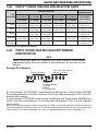
3.03 TWECO
®
FUSION 250A MIG GUN SELECTION GUIDE
Rear
Connection
250 AMP MIG Gun*
Rear Connector
(Replacement)
Part Number
Stock Number
Part Number
Stock Number
Part Number
Stock Number
Part Number
Stock Number
Part Number
Stock Number
Part Number
Stock Number
10 ft cable 12 ft cable 15 ft cable 20 ft cable 25 ft cable
Tweco
®
FV210-3545
1023-1059
FV212-3545
1023-1060
FV215-3545
1023-1061
FV220-3545
1023-1062
FV225-3545
1023-1063
350-174H
2035-2110
Miller
®
FV210M-3545
1023-1067
FV212M-3545
1023-1068
FV215M-3545
1023-1069
FV220M-3545
1023-1070
FV225M-3545
1023-1071
350-174MH
2035-2111
Lincoln
®
----
FV212L-3545
1023-1084
FV215L-3545
1023-1085
---- ----
350-174LH
2035-2112
Euro-Kwik
FV210X-3545
1023-1089
FV212X-3545
1023-1090
FV215X-3545
1023-1091
----
FV225X-3545
1023-1092
174EX-1
2040-2276
252i
ThermalArc
---- ----
FV215TA3545
1023-1097
---- ----
350-174H
2035-2110
*Rear connector supplied as standard
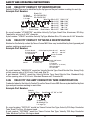
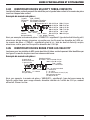
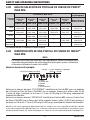
3.04 TWECO FUSION 250A MIG GUN PART NUMBER
IDENTIFICATION
NOTE
Tweco Fusion MIG guns, as a general rule, have a specific nomenclature
incorporated within each part number to help determine the wire size of each
MIG gun.
Example Part Number:
FV215TA3545
T=Tweco
TA=Tweco (Bundle)
L=Lincoln
M=Miller
X, XE=Euro-Kwik
Fusion Velocity
15 foot (5 M) cable
.035"-.045" Wire Capacity
(0,9 mm - 1,2 mm)
So a part number "FV215TA3545" would identify the MIG gun as a: Tweco Fusion 250A MIG
Gun bundle pack with a 8-pin rear connector, 15 foot long cable and having a 0.035" to 0.045"
diameter wire capacity.
So a part number"FV2253545" would identify the MIG gun as a: Tweco Fusion 250A MIG Gun
with a 4-pin Tweco rear connector, 25 foot long cable and having a 0.035" to 0.045" diameter
wire capacity.
MILLER is a registered trademark of Miller Electric Mfg. Co.; ESAB is a registered trademark of ESAB AB; LINCOLN is
a registered trademark of LINCOLN Electric Co.; The aforementioned registered trademarks are no way affiliated with
Tweco Products, Inc. or Victor Technologies, Inc. Tweco is a registered trademark of Victor Technologies, Inc.

8
SAFETY AND OPERATING INSTRUCTIONS
89200015
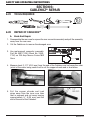
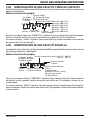
3.04 VELOCITY CONTACT TIP IDENTIFICATION
Velocity Contact Tips may be identified by the tip type and the part number marking for each tip.
Example Part Number:
VTSARZT30
Velocity
Tip
Blank=CU,
RZ=CHROM ZIRC,
RS=SILVER ZIRC
T=Tapered,
Blank=None
S=Small,
M=Medium,
L=Large
A=Aluminum,
Blank=Other
Wire Size: 23=0.023” 116=1/16”
30=0.030” 564=5/64”
35=0.035” 332=3/32”
40=0.040” 764=7/64”
45=0.045” 18=1/8”
52=0.052” 364=3/64”
So a part number "VTSARZT30" would be: Velocity Tip Type, Small Size, Aluminum, RZ Alloy,
Tapered for wire size 0.030" diameter.
A part number "VTM40" would be: Velocity Tip Type, Medium Size, CU, wire size 0.040" diameter.
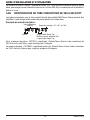
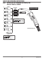
3.05 VELOCITY CONTACT TIP NOZZLE IDENTIFICATION
Nozzles for the Velocity contact tip Tweco Fusion MIG Guns may be identified by their type and part
number marking on each nozzle.
Example Part Number:
Blank=Standard,
H=Heavy Duty
VNSH50FS
Velocity
Nozzle
Blank=Std Recess,
F=Flush,
P=Protrude,
R= Recess ¼” (6.35mm)
FAS=Spot Weld
FC=Flux Core
S=Small Nozzle,
M=Medium Nozzle,
L=Large Nozzle
Orifice Opening Size: 37=3/8” 62=5/8”
50=1/2” 75=3/4”
Blank=Threaded,
S=Slip
So a part number "VNSH50FS" would be: Velocity Nozzle Type, Small Nozzle Size, Heavy Duty,
orifice opening size of 0.50 inch, Flush end, Slip fit.
A part number "VNS50" would be: Velocity Nozzle Type, Small Nozzle Size, Standard Duty,
orifice opening size of 0.50 inch, Standard Recess end, Threaded fit.
3.06 VELOCITY 250 AMP CONDUCTOR TUBE IDENTIFICATION
Conductor tubes for the Velocity Contact Tip on the Tweco Fusion MIG Guns may be identified by their
type and part number marking on each tube.
Example Part Number:
FVCTS45
Fusion
Velocity
Conductor Tube
Bend Angle: 45˚, 60˚, or 180˚
S=Small Tip,
M=Medium Tip,
L=Large Tip
So a part number "FVCTS45" would be: Tweco Fusion Gun Type, Velocity 250 Amp Conductor
Tube, Small Tip Size, 45 degree bend.
A part number "FVCTM60" would be: Tweco Fusion Gun Type, Velocity 250 Amp Conductor
Tube, Medium Tip Size, 60 degree bend.

SAFETY AND OPERATING INSTRUCTIONS
989200015
SECTION 4:
MIG GUN INSTALLATION
NOTE
Be certain that the end user (welder, operator, or helper) reads and understands
these instructions. Be certain that the welder also reads Section 1 “Safety
Precautions.”
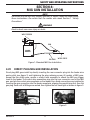
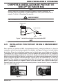
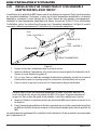
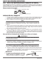
WARNING
Electric shock can cause injury or death.
POWER
SOURCE
WIRE FEEDER
GROUND
WORK PIECE
GUN
Figure 1: Standard MIG Gun Installation
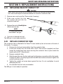
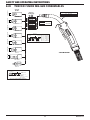
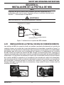
4.01 DIRECT PLUG MIG GUN INSTALLATION
Direct plug MIG guns install by directly inserting the rear connector plug into the feeder wire
guide outlet (see figure 2) and tightening the plug retaining screw. All models of MIG guns,
except the Euro-Kwik guns, require a control wire assembly to attach the MIG gun trigger
leads to the feeder. The control wire assemblies plug into the rear connector case of the MIG
gun, and into the control wire receptacle on the feeder. Euro-Kwik connections are installed by
inserting the gun connection into the feeder receptacle, aligning the conduit plug first, then the
gas plug. Push until all fittings are seated, then tighten the nut hand tight as shown in figure 3.
Figure 2
Figure 3

10
SAFETY AND OPERATING INSTRUCTIONS
89200015
4.02 TWECO
®
MIG-KWIK CONNECTION AND ADAPTER KIT
INSTALLATION
Installation of a Tweco MIG gun with a Tweco connector plug, may require an adapter kit. Choose
the correct adapter kit for your wire feeder from the Adapter Kit Listing Form No. TLAK-97 for
more detail. To install, follow the instructions furnished with the adapter kit. Figure 4 shows
the general adapter kit installation.
Receptacle
(TLAK-1 or 6TLAK-1)
Receptacle
(TAK-1 or 6TAK-1)
ADAPTER PLUG
WIRE FEEDER
GAS HOSE
GAS HOSE
POWER CABLE
CONTROL WIRE
MIG GUN
Figure 4
1. Screw adapter plug into the receptacle and tighten.
2. Insert the adapter plug and receptacle into the wire feeder wire guideout. Tighten the
wire guide attachment screw.
3. If needed, attach a proper sized welding cable from the welding power source to the
receptacle power connection.
4. Attach a gas hose to the receptacle and to the feeder gas solenoid.
NOTE
When using an adapter kit, the gas must be attached to the receptacle to provide
gas to the MIG gun. If the feeder gas supply is attached to the feeder wire guideout
block, it must be rerouted to the receptacle.
5. Insert the MIG gun rear connection plug into the receptacle and tighten the attachment
screw.
6. Attach the control wire plug assembly to the wire feeder MIG gun control circuit. Then
plug the flat double female plug into the MIG gun.
The gun should now be installed and ready to feed wire as recommended by the feeder
manufacturer.

SAFETY AND OPERATING INSTRUCTIONS
1189200015
SECTION 5: REPLACEMENT INSTRUCTIONS
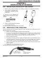
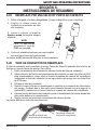
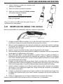
5.01 REPLACING VELOCITY CONTACT TIP
CAUTION
While nozzle and contact tip are removed, maintain an adequate distance of the
wire from metal objects to avoid burnbacks to conduit or conductor tube.
1. Remove worn nozzle and tip. (Clean nozzle if reusing.)
2. Slide new contact tip over
the conduit end and into the
conductor tube end.
3. Replace the nozzle. Hand tighten
(Nozzle secures tip).
NOTE
For proper operation the
nozzle MUST be tight.
4. Trim wire to desired stick out.
The MIG gun is now ready operation.
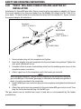
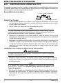
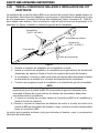
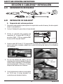
5.02 REPLACE CONDUCTOR TUBE
The conductor tube is attached to the Tweco
®
Fusion handle by two set screws on the side of
the handle. To remove:
1. Remove the front end consumables from the conductor tube.
2. Loosen the conduit liner set screw with a 5/64" Allen wrench (supplied) and then
loosen the socket head cap screw securing the conductor tube in place inside the
handle with a 5/32" Allen wrench.
3. Remove conductor tube.
4. Slide the new tube over the liner and insert into the brass connection within the handle.
Confirm the tube is correctly aligned with the MIG Gun handle and wrench tighten the
socket head cap screw.
5. Tighten the conduit set screw down against the liner. Do not overtighten to avoid
damaging the liner.
6. Re-assemble the front end consumables.
The MIG gun is now ready for operation.

12
SAFETY AND OPERATING INSTRUCTIONS
89200015
Conduit liner set screw
Socket head cap screw
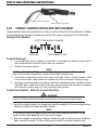
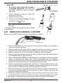
5.03 CONDUIT IDENTIFICATION AND REPLACEMENT
The procedure for removal and installation of a wire conduit is similar for all Tweco MIG guns. Conduits
may be identified by the type of conduit stop and the part number marking on each conduit stop.
Example Part Number:
44-116-15
44 Series
1/16" (1,6mm) Wire Capacity
Liner length in feet
Conduit Removal
1. Lay the MIG gun out on a table or on the floor in a straight line. Make sure the gun is
fully extended and all twists in the cable are removed.
2. Remove the nozzle and tip.
NOTE
On Miller
®
Direct Plug MIG guns, remove the nipple on the end of the connector
plug. On Euro-Kwik connections, remove the conduit retaining cap.
3. Loosen the conduit set screw in the front of the gun. This is usually located at the
front of the handle. Then loosen the conduit set screw in the rear connector plug.
4. Grip the conduit stop and remove the conduit with a twisting motion. On Miller
®
Direct
Plug MIG guns, twisting the rear of the gun approximately one revolution clockwise
will raise the conduit stop out of the connector plug recess.
Conduit Installation - Velocity Contact Tip Style
WARNING
Failure to follow Conduit Installation Instructions will cause wire feed issues.
1. Uncoil the conduit and lay it in a straight line. Insert the conduit into the rear connector plug.
Push the conduit into the gun with short strokes.
NOTE
If the conduit hangs up gently whip the cable while applying pressure to the
conduit. New liners must be cut to the correct length.
2. When the conduit is completely in the gun, tighten the rear conduit set screw. On Miller
®
guns, reinstall the nipple. On Euro-Kwik guns, reinstall the conduit retaining cap.

SAFETY AND OPERATING INSTRUCTIONS
1389200015
IMPORTANT!
3. The new conduit liner will need to be cut to length.
This can be done by trimming the conduit to the
appropriate length.
1/8” (3,2 mm)
Velocity
Conductor Tube
4. File the cut conduit end to remove burrs.
5. Replace the contact tip.
6. Replace the nozzle. Hand tighten
(Nozzle secures tip).
NOTE
For proper operation the nozzle MUST
be tight.
The MIG gun is now ready to be reinstalled on the
feeder.
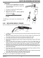
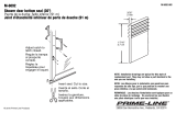
5.04 REPLACING HANDLE, TRIGGER
Remove the MIG gun from the feeder prior to beginning these steps.
Handle screws Back Cap
Gun Hanger
1. Lay MIG gun on side, screw side up and remove both handle screws at the front of the
gun handle.
2. Remove the small screw from the other side of the gun hanger clip and remove the
gun hanger clip being careful to keep all internal components in place.
3. Lay the gun back down on its side and untwist the handle back cap.
4. Remove the top handle half being careful to keep all components in place in the lower
handle half.
5. (Follow this step ONLY if the trigger is to be replaced.) Lift out the molded trigger, the
trigger mechanism, and disconnect the lead wires. Connect the wires to the new trigger
mechanism then place the molded trigger and new trigger in the lower handle half.
6. Place the new top handle half on the old lower handle half and gently flip the gun over.
Replace the old lower handle half with the new lower handle half. Molded trigger should
move within the handle.
7. Flip the gun back to the screw side up and press the handle halves together until they
bottom. Be careful not to pinch the trigger lead wires.
8. Put the gun hanger in place and install the two handle screws. Rotate the gun handle
to the other side and install the small gun hanger clip screw.
9. Slide the Back Cap into place and twist onto the handle end.
The MIG gun is now ready to be reinstalled on the feeder.

14
SAFETY AND OPERATING INSTRUCTIONS
89200015
SECTION 6:
CABLEHOZ
®
REPAIR
6.01 TOOLS REQUIRED
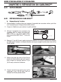
6.02 REPAIR OF CABLEHOZ
®
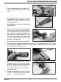
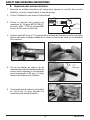
A. Back-End Repair
1. Disassemble the rear case to expose the rear connector assembly and pull the assembly
away from the rear case.
2. Cut the Cablehoz
®
to remove the damaged area.
3. Use replacement connector assembly,
Part No. MS172-RK (Stock No. 2060-
2134) on 250 Amp Tweco
®
Fusion MIG
Guns.
4. Measure back 2-1/2" (63,5 mm) from the end of the Cablehoz and cut away the outer
jacket of the cable, being careful not to cut the copper strands and or lead wires.
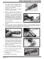
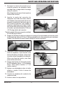
5. Pull the copper strands and lead
wires away from the inner core tube
that is exposed and cut away leaving
approximately ¼" (6,35 mm) past the
end of the end of the Cablehoz.

SAFETY AND OPERATING INSTRUCTIONS
1589200015
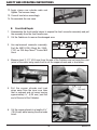
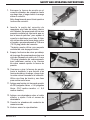
6. Cut the copper strands to a length of ¾"
(19,05 mm) while leaving the wire leads
intact.
7. Thread the pressure nut onto the
replacement rear connector until it
bottoms out and then slide the sleeve
over the connector.
Note: Make sure the bevel is facing the
right direction.
Bevel
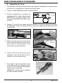
8. Insert the replacement connector nipple
into the inner core tube of the Cablehoz.
It is recommended to use a small amount
of non-petroleum based lubricant* to help
the connector to slide into the tube. The
core tube should bottom out against the
shoulder, approximately 15/16" (23,8
mm) onto the connector.
*A small amount of white glue works well.
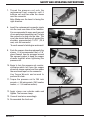
9. Push the copper strands underneath the sleeve. It is recommended that a 1/8” glass
filament tape be wrapped around the exposed copper to keep the copper strands together
when tightening the pressure nut.
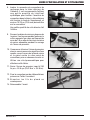
10. Begin to turn the pressure nut counter-
clockwise which will force the copper
strands & sleeve against and then under
the machined taper on the connector.
Use Torque Wrench and wrench to
perform this task.
11. Torque the pressure nut to 250 inch
pounds, +/-50 inch pounds, (28,2 newton
meters, +/- 5,6 newton meters).

16
SAFETY AND OPERATING INSTRUCTIONS
89200015
12. Apply clamp over outside cable and
tighten. Trim excess clamp.
13. Connect lead wires accordingly.
14. Re-assemble the rear case.
Approx.
0.2” (5mm)
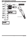
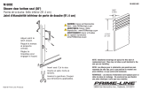
B. Front-End Repair
1. Disassemble the front handle halves to expose the front connector assembly and pull
the assembly from the front handle case.
2. Cut the Cablehoz
®
to remove the damaged area.
3. Use replacement connector assembly,
Part No. MS102-RK (Stock No. 2060-
2132) on 250 Amp Tweco
®
Fusion MIG
Guns.
4. Measure back 2-1/2” (63,5 mm) from the end of the Cablehoz and cut away the outer
jacket of the cable, being careful not to cut the copper strands and or lead wires.
5. Pull the copper strands and lead
wires away from the inner core tube
that is exposed and cut away leaving
approximately ¼” (6,35 mm) past the
end of the end of the Cablehoz.
6. Cut the copper strands to a length of ¾”
(19,05 mm) while leaving the wire leads
intact.

SAFETY AND OPERATING INSTRUCTIONS
1789200015
7. Thread the pressure nut onto the
replacement front connector until it
bottoms out and then slide the sleeve
over the connector.
Note: Make sure the bevel is facing the
right direction.
Bevel
8. Insert the replacement connector nipple
into the inner core tube of the Cablehoz.
It is recommended to use a small amount
of non-petroleum based lubricant* to help
the connector to slide into the tube. The
core tube should bottom out against the
shoulder, approximately 15/16” (23,8
mm) onto the connector.
*A small amount of white glue works well.
9. Push the copper strands underneath the
sleeve. It is recommended that a 1/8”
glass filament tape be wrapped around
the exposed copper to keep the copper
strands together when tightening the
pressure nut.
10. Begin to turn the pressure nut counter-
clockwise which will force the copper
strands & sleeve against and then under
the machined taper on the connector.
Use Torque Wrench and wrench to
perform this task.
11. Torque the pressure nut to 250 inch
pounds, +/-50 inch pounds, (28,2 newton
meters, +/- 5,6 newton meters).
12. Apply clamp over outside cable and
tighten. Trim excess clamp.
13. Connect lead wires accordingly.
14. Re-assemble the front end.
Approx.
2” (5mm)

18
SAFETY AND OPERATING INSTRUCTIONS
89200015
This page intentionally blank.
La page est en cours de chargement...
La page est en cours de chargement...
La page est en cours de chargement...
La page est en cours de chargement...
La page est en cours de chargement...
La page est en cours de chargement...
La page est en cours de chargement...
La page est en cours de chargement...
La page est en cours de chargement...
La page est en cours de chargement...
La page est en cours de chargement...
La page est en cours de chargement...
La page est en cours de chargement...
La page est en cours de chargement...
La page est en cours de chargement...
La page est en cours de chargement...
La page est en cours de chargement...
La page est en cours de chargement...
La page est en cours de chargement...
La page est en cours de chargement...
La page est en cours de chargement...
La page est en cours de chargement...
La page est en cours de chargement...
La page est en cours de chargement...
La page est en cours de chargement...
La page est en cours de chargement...
La page est en cours de chargement...
La page est en cours de chargement...
La page est en cours de chargement...
La page est en cours de chargement...
La page est en cours de chargement...
La page est en cours de chargement...
La page est en cours de chargement...
La page est en cours de chargement...
La page est en cours de chargement...
La page est en cours de chargement...
La page est en cours de chargement...
La page est en cours de chargement...
La page est en cours de chargement...
La page est en cours de chargement...
La page est en cours de chargement...
La page est en cours de chargement...
La page est en cours de chargement...
La page est en cours de chargement...
La page est en cours de chargement...
La page est en cours de chargement...
La page est en cours de chargement...
La page est en cours de chargement...
La page est en cours de chargement...
La page est en cours de chargement...
La page est en cours de chargement...
La page est en cours de chargement...
La page est en cours de chargement...
La page est en cours de chargement...
La page est en cours de chargement...
La page est en cours de chargement...
La page est en cours de chargement...
La page est en cours de chargement...
La page est en cours de chargement...
La page est en cours de chargement...
La page est en cours de chargement...
La page est en cours de chargement...
La page est en cours de chargement...
La page est en cours de chargement...
La page est en cours de chargement...
La page est en cours de chargement...
La page est en cours de chargement...
La page est en cours de chargement...
-
 1
1
-
 2
2
-
 3
3
-
 4
4
-
 5
5
-
 6
6
-
 7
7
-
 8
8
-
 9
9
-
 10
10
-
 11
11
-
 12
12
-
 13
13
-
 14
14
-
 15
15
-
 16
16
-
 17
17
-
 18
18
-
 19
19
-
 20
20
-
 21
21
-
 22
22
-
 23
23
-
 24
24
-
 25
25
-
 26
26
-
 27
27
-
 28
28
-
 29
29
-
 30
30
-
 31
31
-
 32
32
-
 33
33
-
 34
34
-
 35
35
-
 36
36
-
 37
37
-
 38
38
-
 39
39
-
 40
40
-
 41
41
-
 42
42
-
 43
43
-
 44
44
-
 45
45
-
 46
46
-
 47
47
-
 48
48
-
 49
49
-
 50
50
-
 51
51
-
 52
52
-
 53
53
-
 54
54
-
 55
55
-
 56
56
-
 57
57
-
 58
58
-
 59
59
-
 60
60
-
 61
61
-
 62
62
-
 63
63
-
 64
64
-
 65
65
-
 66
66
-
 67
67
-
 68
68
-
 69
69
-
 70
70
-
 71
71
-
 72
72
-
 73
73
-
 74
74
-
 75
75
-
 76
76
-
 77
77
-
 78
78
-
 79
79
-
 80
80
-
 81
81
-
 82
82
-
 83
83
-
 84
84
-
 85
85
-
 86
86
-
 87
87
-
 88
88


Tweco TWECO® FUSION™250 Air-Cooled Mig Gun 250 AMP Manuel utilisateur
- Taper
- Manuel utilisateur
- Ce manuel convient également à
dans d''autres langues
Documents connexes
-
 Tweco Classic No. Series Mig Guns with Velocity Consumables Manuel utilisateur
-
 Tweco Classic Serial No. Mig Guns Manuel utilisateur
-
 Tweco Classic No. Series Mig Guns Manuel utilisateur
-
 Tweco Tweco Spool Gun Manuel utilisateur
-
 Tweco Classic No. Series Mig Guns Manuel utilisateur
-
 Tweco Classic No. Series Mig Guns Manuel utilisateur
-
 Tweco Air-Cooled 350 AMP 450 AMP Water-Cooled 400 AMP 500 AMP PulseMaster™ Mig Gun Manuel utilisateur
-
Tweco Tweco Spray Master MIG Guns with VELOCITY2 Manuel utilisateur
-
-


Autres documents
-
ESAB 220 AMP Manuel utilisateur
-
-
Tweco Robotics Light Weight Quick Robotics Torch Guide d'installation
-
 Prime-Line M 6092 Mode d'emploi
-
ESAB FABRICATOR252i Manuel utilisateur
-
-
-
 Thermal Arc 400SP 500SP Powermaster Automation Manuel utilisateur
-
Ryobi P307 Le manuel du propriétaire
-
 Prime-Line M 6092 Guide d'installation


