
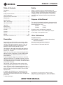
INSTRUCTION MANUAL
99936623 REV 4 © 2019 Greenlee Tools, Inc. 2/19
Read and understand all of the instructions and
safety information in this manual before operating
or servicing this tool.
Register this product at www.greenlee.com
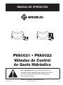
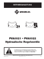
PVA0021 • PVA0022
Hydraulic Control Valves

PVA0021 • PVA0022
Greenlee Tools, Inc. 4455 Boeing Dr. • Rockford, IL 61109-2988 USA • 815-397-7070
2
Safety
Safety is essential in the use and maintenance of
Greenlee tools and equipment. This instruction manual
and any markings on the tool provide information for
avoiding hazards and unsafe practices related to the
use of this tool. Observe all of the safety information
provided.
Purpose of this Manual
This manual is intended to familiarize all personnel with
the safe operation and maintenance procedures for the
following Greenlee valves:
PVA0021 (42948)
PVA0022 (42949)
Keep this manual available to all personnel.
Replacement manuals are available upon request
at no charge at www.greenlee.com.
Other Publications
Tool Owners/Users
SAE Standard J1273 (Hose and Hose Assemblies):
Publication 99930323
Greenlee Authorized Service Centers
Service Manual: Publication 99912872
All specications are nominal and may change as design
improvements occur. Greenlee Tools, Inc. shall not be liable for
damages resulting from misapplication or misuse of its products.
KEEP THIS MANUAL
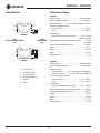
Table of Contents
Description .................................................................... 2
Safety ............................................................................ 2
Purpose of this Manual ................................................. 2
Other Publications ......................................................... 2
Important Safety Information ..................................... 3-5
Identication .................................................................. 6
Specications ............................................................. 6-7
Hoses and Fittings ........................................................ 8
Hose Connections ......................................................... 8
Operation ....................................................................... 9
Maintenance ................................................................ 10
Troubleshooting ........................................................... 11
Español ........................................................................ 13
Français ....................................................................... 25
Deutsch ....................................................................... 37
Italiano ......................................................................... 49
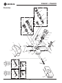
Illustrations and Parts Lists .................................... 60-64
Description
Greenlee Remote Control Valves are compact, light-
weight, high-pressure valves rated for a maximum of
700 bar (10,000 psi) of hydraulic pressure. They are
intended to provide control for hydraulic tools that
operate on Open-Center hydraulic systems.
The PVA0021 is for single-acting tools and features a
3/8" coupler. The PVA0022 is for double-acting tools
and has 1/4" couplers.
These four-way valves have three operating positions:
Advance, Neutral, and Retract. A special hold feature
locks the tool in its stroke when the lever is in the
neutral position.
To reduce operator fatigue, they feature an automatic
spring-returned lever. This provides automatic shut-off
and returns the valve to neutral when the hydraulic sys-
tem’s operating pressure is achieved, or when the tool is
at the end of its stroke.
For operator safety, Greenlee remote control valves
include a ground dump relief valve in the valve return
circuit. This relief valve will automatically open if the
return couplers are not connected properly. The ground
dump relief pressure for each model is listed in under
Specications.
In addition, the PVA0022 has an internal relief valve
that limits the tool retract pressure. This feature pro-
tects tools that cannot withstand a return-side pressure
greater than:
• 345 bar (5000 psi)

PVA0021 • PVA0022
Greenlee Tools, Inc. 4455 Boeing Dr. • Rockford, IL 61109-2988 USA • 815-397-7070
3
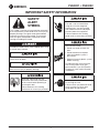
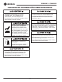
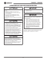
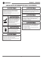
IMPORTANT SAFETY INFORMATION
SAFETY
ALERT
SYMBOL
This symbol is used to call your attention to hazards
or unsafe practices which could result in an injury or
property damage. The signal word, dened below,
indicates the severity of the hazard. The message
after the signal word provides information for pre-
venting or avoiding the hazard.
Immediate hazards which, if not avoided, WILL result
in severe injury or death.
Hazards which, if not avoided, COULD result in
severe injury or death.
Hazards or unsafe practices which, if not avoided,
MAY result in injury or property damage.
Read and understand all of the
instructions and safety information
in this manual before operating or
servicing this tool.
Failure to observe this warning
could result in severe injury or death.
Electric shock hazard:
This tool is not insulated. When
using this unit near energized
electrical lines, use only certied
non-conductive hoses and proper
personal protective equipment.
Failure to observe this warning
could result in severe injury or death.
Skin injection hazard:
• Do not use hands to check for
leaks.
• Do not hold hose or couplers
while
the hydraulic system is
pressurized.
• Depressurize the hydraulic system
before servicing.
Oil under pressure easily punctures
skin causing serious injury, gan-
grene or death. If you are injured by
escaping oil, seek medical attention
immediately.
Wear eye protection when operating
or servicing this tool.
Failure to wear eye protection could
result in serious eye injury from
ying debris or hydraulic oil.

PVA0021 • PVA0022
Greenlee Tools, Inc. 4455 Boeing Dr. • Rockford, IL 61109-2988 USA • 815-397-7070
4
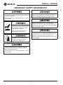
Use hoses, ttings, and other components rated
for 700 bar (10,000 psi). An under-rated component
may fail under pressure.
Failure to observe this warning could result in severe
injury or death.
Valve and other components may be
hot during and after operation. Allow
to cool before handling, or handle
with heat-resistant gloves.
Failure to observe this warning
could result in severe injury.
Wear gloves when using this tool.
Failure to observe this warning
could result in serious injury.
Do not exceed the maximum hydraulic ow, pres-
sure relief or back pressure listed in the specica-
tions section of this manual.
Failure to observe this warning could result in severe
injury or death.
Do not disconnect valve, hoses or ttings while the
power source is running or if the hydraulic uid is
hot. Hot hydraulic uid can cause serious burns.
Do not reverse hydraulic ow. Operation with
hydraulic ow reversed can cause tool malfunction.
Connect the pressure (supply) hose and tank (return)
hose to the proper ports.
Do not change accessories, inspect, adjust or
clean valve when it is connected to a power source.
Accidental start-up can result in serious injury.
Failure to observe this warning could result in severe
injury or death.
IMPORTANT SAFETY INFORMATION

PVA0021 • PVA0022
Greenlee Tools, Inc. 4455 Boeing Dr. • Rockford, IL 61109-2988 USA • 815-397-7070
5
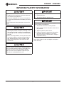
IMPORTANT SAFETY INFORMATION
Hydraulic oil can cause skin irritation.
• Handle the valve and hoses with care to prevent
skin contact with hydraulic oil.
• In case of accidental skin contact with hydraulic
oil, wash the affected area immediately to remove
the oil.
Failure to observe these precautions may result in
injury.
• Inspect the hydraulic hoses and couplings every
operating day. Repair or replace if leakage, crack-
ing, wear or damage is evident. Damaged hoses
or couplings can fail, resulting in injury or property
damage.
• Make sure all bystanders are away from the work
area when handling, starting, and operating the
tool. Nearby personnel can be injured by ying
debris or by ying parts in the event of a tool
malfunction.
Use the valve for manufacturer’s intended purpose
only. Use other than that which is instructed in this
manual can result in injury or property damage.
Do not use this valve to operate a hydraulic jack.
The valve is not intended for this use.
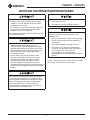
Emergency stop procedure:
1. Release the lever.
2. Shut off the hydraulic power source.
Procedure for connecting or disconnecting hydraulic
hoses, ttings or components:
1. Set the PVA valve to the neutral position.
2. Move the ow lever on the power source to the
OFF position.
3. Stop the hydraulic power source.
4. Follow the sequence under Hose Connections
to prevent pressure buildup. In case some
pressure has built up, loosen hoses, ttings or
components slowly.
Note: Keep all decals clean and legible, and replace
when necessary.

PVA0021 • PVA0022
Greenlee Tools, Inc. 4455 Boeing Dr. • Rockford, IL 61109-2988 USA • 815-397-7070
6
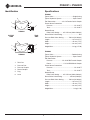
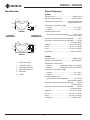
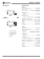
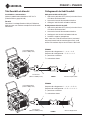
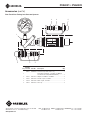
Identification
1. Tank Port
2. Pressure Port
3. Pressure Coupler
4. Return Coupler
5. Plug
6. Lever
1
2
3
4
6
1
2
3
5
6
PVA0021
PVA0022
SUPPLY
SIDE
TOOL
SIDE
Specifications
PVA0021
Type of Valve .................................................Single-Acting
Type of Hydraulic System ............................. Open-Center
Tool Connection .................3/8–18 Female Quick Coupler
Power Source Connection
Pressure ......................................................1/4–18 NPT
Tank ............................................................1/4–18 NPT
Ground Dump
Relief Valve Setting ......... 207–276 bar (3000–4000 psi)
Return Relief Valve Setting .......................................... N/A
Pressure Relief Valve Setting ............. 700 bar (10,000 psi)
Length ..........................................................231 mm (9.1")
Width ............................................................45 mm (1.75")
Height ...........................................................83 mm (3.25")
Weight/Mass .............................................. 1.3 kg (2.75 lb)
PVA0022
Type of Valve ...............................................Double-Acting
Type of Hydraulic System ............................. Open-Center
Tool Connection
Pressure ........................1/4–18 NPSM Female Coupler
Return ...............................1/4–18 NPSM Male Coupler
Power Source Connection
Pressure ......................................................1/4–18 NPT
Tank ............................................................1/4–18 NPT
Ground Dump
Relief Valve Setting ........ 207–276 bar (3000–4000 psi)
Return Relief Valve Setting ................... 345 bar (5000 psi)
Pressure Relief Valve Setting ............. 700 bar (10,000 psi)
Length ..........................................................191 mm (7.5")
Width ............................................................45 mm (1.75")
Height ...........................................................83 mm (3.25")
Weight/Mass ................................................ 1.2 kg (2.5 lb)

PVA0021 • PVA0022
Greenlee Tools, Inc. 4455 Boeing Dr. • Rockford, IL 61109-2988 USA • 815-397-7070
7
Specifications (cont’d)
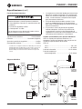
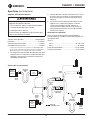
Hydraulic Power Source
Do not exceed the following hydraulic power source
maximums:
• Hydraulic ow: See the product specications
• Pressure relief: 138 bar (2000 psi)
• Back pressure: 13.8 bar (200 psi)
Failure to observe this warning could result in severe
injury or death.
Type of Hydraulic System ............................. Open-Center
Filtration ............................................. 10 Micron (nominal)
Pressure Relief Setting .......................... 138 bar (2000 psi)
Back Pressure (Maximum)* .................... 13.8 bar (200 psi)
* 13.8 bar (200 psi) is the maximum agreed standard back pressure
for the HTMA (Hydraulic Tool Manufacturers Association).
Greenlee tools will operate satisfactorily at this standard.
1. Maximum hydraulic uid temperature must not
exceed 60 °C (140 °F). A sufcient oil cooling
capacity is needed to limit the hydraulic uid
temperature.
2. Hydraulic ow must not exceed 5 l/min (1.32 gpm).
Install a ow meter in the return line to measure to
rate of hydraulic ow before using the tool.
3. Pressure relief valve setting must not exceed
138bar (2000 psi) at your tool’s maximum ow.
Locate the pressure relief valve in the supply circuit
to limit excessive hydraulic pressure to the tool.
Recommended Hydraulic Fluids
Use any non-detergent, petroleum-based hydraulic
uid which meets the following specications or HTMA
specications.
S.U.S. @:
38 °C (100 °F) ...............................................140 to 225
99 °C (210 °F) ............................................ 40 minimum
Flash Point .................................170 °C (340 °F) minimum
Pour Point ...................................-34 °C (-30 °F) minimum
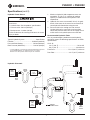
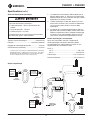
T
P
POWER
SOURCE
2,000 PSI
FLOW
ON/OFF
VALVE
MEDIUM
PRESSURE
HOSES
T
P
INTENSIFIER
4,000-
10,000 PSI
P
T
T
P
VALVE
VALVE
T
P
HIGH
PRESSURE
PUMP
4,000-
10,000 PSI
FLOW
ON/OFF
VALVE
SYMBOL FOR
DISCONNECT COUPLER
R
P
P
T
P
TOOL
REMOTE
COUPLING
HIGH
PRESSURE
HOSES
P
T
P
TOOL
DIRECT
COUPLING
P
SINGLE
ACTING
OUT
IN
HIGH
PRESSURE
HOSES
OUT
IN
DIRECT CONNECT
DOUBLE ACTING
Hydraulic Schematic

PVA0021 • PVA0022
Greenlee Tools, Inc. 4455 Boeing Dr. • Rockford, IL 61109-2988 USA • 815-397-7070
8
Hoses and Fittings
Installation and Maintenance
See publication 99930323, SAE J1273
(Hose and Hose Assemblies)
Replacement
Refer to a Greenlee catalog or bulletin 99910322 for a
complete selection of hoses and ttings.
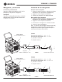
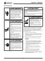
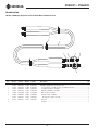
Hose Connections
Connecting Hoses
1. Move the ow lever on the power source to the OFF
position.
2. Stop the hydraulic power source.
3. Connect the hoses in the order shown.
Disconnecting Hoses
1. Move the ow lever on the power source to the OFF
position.
2. Stop the hydraulic power source.
3. Disconnect the hoses in the order shown.
4. Install dust caps.
Note: Return (tank) hose connection should always be
connected before supply (pressure) hose connection to
prevent pressure buildup inside the unit.
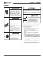
4
5
2
1
3
PVA0021
T
P
2
4
1
3
PVA0022
5
6
T
P
Power Source
(138 bar or 2000 psi max.)
Power Source
(138 bar or 2000 psi max.)
Intensifier
(700 bar or 10,000 psi max.)
Intensifier
(700 bar or 10,000 psi max.)
Single-Acting Tool
Double-Acting Tool
PVA0021
Connection Sequence: 1 – 2 – 3 – 4 – 5
Disconnection Sequence: 5 – 4 – 3 – 2 – 1
P = pressure, or supply
T = tank, or return
PVA0022
Connection Sequence: 1 – 2 – 3 – 4 – 5 – 6
Disconnection Sequence: 6 – 5 – 4 – 3 – 2 – 1
P = pressure, or supply
T = tank, or return

PVA0021 • PVA0022
Greenlee Tools, Inc. 4455 Boeing Dr. • Rockford, IL 61109-2988 USA • 815-397-7070
9
Operation
Electric shock hazard:
This tool is not insulated. When
using this unit near energized
electrical lines, use only certied
non-conductive hoses and proper
personal protective equipment.
Failure to observe this warning
could result in severe injury or death.
Skin injection hazard:
• Do not use hands to check for
leaks.
• Do not hold hose or couplers
while
the hydraulic system is
pressurized.
• Depressurize the hydraulic system
before servicing.
Oil under pressure easily punctures
skin causing serious injury, gan-
grene or death. If you are injured by
escaping oil, seek medical attention
immediately.
Wear eye protection when operating
or servicing this tool.
Failure to wear eye protection could
result in serious eye injury from
ying debris or hydraulic oil.
Use hoses, ttings, and other components rated
for 700 bar (10,000 psi). An under-rated component
may fail under pressure.
Failure to observe this warning could result in severe
injury or death.
Valve and other components may be
hot during and after operation. Allow
to cool before handling, or handle
with heat-resistant gloves.
Failure to observe this warning
could result in severe injury.
Note: Maintain proper footing and balance while using
the tool. Do not over-reach. Unsuitable footing and
balance may not allow counteracting normal or unex-
pected movement of the tool.
1. Start the power source.
Note: Allow the power source to run for a few
minutes to warm the hydraulic fluid.
2. Position the tool in the appropriate location or
position.
3. To start the tool, press the lever to ADVANCE.
Notes:
• When the hydraulic pressure reaches 207 bar to
276 bar (3000 psi to 4000 psi), you may release
the lever and it will stay in the ADVANCE position.
The tool will continue to advance until the intensi-
fier reaches 700 bar (10,000 psi).
• You may stop the tool at any time by pressing the
lever to NEUTRAL.
4. To retract the tool, press the lever to RETRACT.
5. When the tool is not in use, stop the power source
to reduce heat and wear on tool components.

PVA0021 • PVA0022
Greenlee Tools, Inc. 4455 Boeing Dr. • Rockford, IL 61109-2988 USA • 815-397-7070
10
Maintenance
Wear eye protection when operating
or servicing this tool.
Failure to wear eye protection could
result in serious eye injury from
ying debris or hydraulic oil.
Do not change accessories, inspect, adjust or
clean valve when it is connected to a power source.
Accidental start-up can result in serious injury.
Failure to observe this warning could result in severe
injury or death.
Use this maintenance schedule to maximize the tool’s
service life.
Notes: Keep decals clean and legible. Replace when
necessary — see the decals in the Parts List.
When disposing of any components (hydraulic hoses,
hydraulic fluid, worn parts, etc.), do so in accordance
with federal, state and local laws or ordinances.
Daily
1. Wipe all tool surfaces clean.
2. Inspect the hydraulic hoses and ttings for signs
of leaks, cracks, wear or damage. Replace if
necessary.
3. Install dust caps when the tool is disconnected.
Monthly
1. Perform a thorough inspection of the hydrau-
lic hoses and ttings as instructed in publication
99930323, SAE J1273 (Hose and Hose Assemblies).
2. Check the pressure to the tool by installing an in-line
pressure gauge, rated for 700 bar (10,000psi),
between the valve and the tool.
Annually
If required by your organization, have the tool inspected
by an authorized Greenlee service center.

PVA0021 • PVA0022
Greenlee Tools, Inc. 4455 Boeing Dr. • Rockford, IL 61109-2988 USA • 815-397-7070
11
Problem Probable Cause Probable Remedy
Tool does not operate. Improper power source. Verify that the power source meets
the specications. Refer to the
Specications section.
Hydraulic uid level low. Check the uid level. Check system for
leaks.
Incorrect hydraulic uid viscosity. Use hydraulic uid with the correct
viscosity. Refer to the Specications
section.
Tool operates slowly or
erratically.
Hydraulic uid cold. Allow uid to warm to the operating
temperature. Actuate the tool intermit-
tently to reduce the warming time.
Power source not adjusted correctly. Refer to the power source operator’s
manual. Set the ow and pressure to
correspond with the tool.
Hydraulic uid level low. Check the uid level. Check system for
leaks.
Air in the hydraulic system. Refer to the power source manufac-
turer’s instructions for removing air from
the system.
Incorrect hydraulic uid viscosity. Use hydraulic uid with the correct
viscosity. Refer to the Specications
section.
Tool feels hot. Hydraulic uid level low. Check the uid level. Check for leaks.
Incorrect hydraulic uid viscosity. Use hydraulic uid with the correct
viscosity. Refer to the Specications
section.
Hydraulic uid dirty. Refer to the power source owner’s
manual for procedure to replace
hydraulic oil and lter.
Troubleshooting
Before troubleshooting, determine whether the problem
is in the tool, the hoses, or the power source. Substitute
a tool, hoses, or power source known to be in good
working order to eliminate the item that is not operating.
If the problem is in the tool, see the troubleshoot-
ing table in this manual. If the problem is in the power
source, see the troubleshooting section of the power
source instruction manual.

PVA0021 • PVA0022
Greenlee Tools, Inc. 4455 Boeing Dr. • Rockford, IL 61109-2988 USA • 815-397-7070
12

MANUAL DE OPERACIÓN
99936623 REV 4 © 2019 Greenlee Tools, Inc. 2/19
Lea y entienda todas las instrucciones y la in-
formación sobre seguridad que aparecen en este
manual, antes de manejar esta herramienta o
darle mantenimiento.
Registre este producto en www.greenlee.com
PVA0021 • PVA0022
Válvulas de Control
de Gasto Hidráulico

PVA0021 • PVA0022
Greenlee Tools, Inc. 4455 Boeing Dr. • Rockford, IL 61109-2988 USA • 815-397-7070
14
Acerca de la seguridad
Es fundamental observar métodos seguros al utilizar
y dar mantenimiento a las herramientas y equipo
Greenlee Utility. Este manual de instrucciones y todas
las marcas que ostenta la herramienta le ofrecen la
información necesaria para evitar riesgos y hábitos
poco seguros relacionados con su uso. Siga toda la
información sobre seguridad que se proporciona.
Propósito de este manual
Este manual tiene como propósito familiarizar al
personal con los procedimientos de operación y
mantenimiento seguros para las siguientes válvulas
Greenlee Utility:
PVA0021 (42948)
PVA0022 (42949)
Mantenga siempre este manual al alcance de todo el
personal.
Puede obtener copias adicionales de manera gratuita,
previa solicitud en www.greenlee.com.
Otras publicaciones
Para propietarios o usuarios
Norma SAE J1273 (Manguera y conjuntos de
mangueras): Publicación 99930323
Centros de Servicio Autorizado Greenlee Utility
Manual de Mantenimiento: Publicación 99912872
Todas las especicaciones son nominales y pueden cambiar conforme
tengan lugar mejoras de diseño. Greenlee Tools, Inc. no se hace
responsable de los daños que puedan surgir de la mala aplicación o
mal uso de sus productos.
CONSERVE ESTE MANUAL
Índice
Descripción ................................................................. 14
Acerca de la seguridad ................................................ 14
Propósito de este manual ........................................... 14
Otras publicaciones .................................................... 14
Importante Información sobre Seguridad ..............15-17
Identicación ............................................................... 18
Especicaciones .................................................... 18-19
Mangueras y accesorios ............................................. 20
Conexión de las mangueras ........................................ 20
Operación .................................................................... 21
Mantenimiento ............................................................. 22
Diagnóstico y solución de fallas .................................. 23
Descripción
Las válvulas de control remoto Greenlee Utility son
compactas, livianas, de alta presión y clasicadas para
una presión hidráulica máxima de 700 Bar (10.000 lb./
pulg.
2
). Están diseñadas para controlar herramientas
hidráulicas que funcionan en sistemas hidráulicos de
circuito abierto.
La PVA0021 es adecuada para herramientas de simple
efecto y cuenta con un acoplador de 3/8 pulg. La
PVA0022 es adecuada para herramientas de doble
efecto y cuenta con un acoplador de 1/4 pulg.
Estas válvulas de cuatro pasos tienen tres posiciones
de funcionamiento: Avanzar, Neutro y Retraer. Un
mecanismo especial de retención traba la herramienta
en su recorrido si la palanca se encuentra en neutro.
Para reducir la fatiga del operador, se cuenta con una
palanca de retorno elástico automático. Esto permite
el cierre automático y regresa la válvula a neutro si
se alcanza la presión de funcionamiento del sistema
hidráulico o si la herramienta llega al nal de su
recorrido.
Para la seguridad del operador, las válvulas de control
remoto Greenlee Utility incluyen un aliviador de
descarga rápida al suelo en el circuito de retorno de
las válvulas. Este aliviador se abre automáticamente
si los acopladores de retorno no están conectados de
manera adecuada. Bajo la sección “Especicaciones”
se indica la presión de descarga rápida al suelo para
cada modelo.
Además, la PVA0022 cuenta con un aliviador interno
que restringe la presión de retracción de la herramienta.
Esta característica protege las herramientas que no
toleran una presión en la vía de retorno mayor de:
• 345 Bar (5.000 lb./pulg.
2
)

PVA0021 • PVA0022
Greenlee Tools, Inc. 4455 Boeing Dr. • Rockford, IL 61109-2988 USA • 815-397-7070
15
IMPORTANTE INFORMACIÓN SOBRE SEGURIDAD
SÍMBOLO
DE ALERTA
SOBRE
SEGURIDAD
Este símbolo se utiliza para indicar un riesgo
o práctica poco segura que podría ocasionar
lesiones o daños materiales. Cada uno de los
siguientes términos denota la gravedad del riesgo. El
mensaje que sigue a dichos términos le indica cómo
puede evitar o prevenir ese riesgo.
Peligros inmediatos que, de no evitarse,
OCASIONARÁN graves lesiones o incluso la muerte.
Peligros que, de no evitarse, PODRÍAN OCASIONAR
graves lesiones o incluso la muerte.
Peligro o prácticas peligrosas que, de no evitarse,
PUEDEN OCASIONAR lesiones o daños materiales.
Lea y entienda todas las
instrucciones y la información sobre
seguridad que aparecen en este
manual, antes de manejar esta
herramienta o darle mantenimiento.
De no observarse esta advertencia
pueden sufrirse graves lesiones o
incluso la muerte.
Peligro de electrocución:
Esta herramienta no está aislada.
Cuando utilice esta unidad cerca
de líneas eléctricas energizadas,
utilice únicamente mangueras no
conductivas aprobadas y equipo de
protección personal adecuado.
De no observarse esta advertencia
pueden sufrirse graves lesiones o
incluso la muerte.
Peligro de inyección cutánea:
• No use las manos para localizar
fugas.
• No toque la manguera ni
los acopladores mientras el
sistema hidráulico se encuentre
presurizado.
• Purgue la presión en el sistema
hidráulico antes de darle
mantenimiento.
El aceite bajo presión punza la
piel fácilmente provocando graves
lesiones, gangrena o la muerte.
Si se lesiona debido a una fuga de
aceite, solicite atención médica de
inmediato.
Utilice protectores para ojos al
manejar o darle mantenimiento a
esta herramienta.
De no utilizar protectores para
ojos puede sufrir graves lesiones
oculares ocasionadas si el aceite
para aparatos hidráulicos, o restos
de materiales llegaran a saltar.

PVA0021 • PVA0022
Greenlee Tools, Inc. 4455 Boeing Dr. • Rockford, IL 61109-2988 USA • 815-397-7070
16
Utilice mangueras, accesorios y demás
componentes especicados para 700 Bar
(10.000 lb./pulg.
2
). Si el componente está
subclasicado, puede fallar bajo presión.
De no observarse esta advertencia pueden sufrirse
graves lesiones o incluso la muerte.
La válvula y otros componentes
pueden alcanzar temperaturas
sumamente altas mientras están
en operación o incluso una vez que
han sido apagados. Permita que se
enfríe antes de manejar, o maneje
con guantes resistentes al calor.
De no observarse esta advertencia
pueden sufrirse graves lesiones.
Utilice guantes al manejar esta
herramienta.
De no observarse esta advertencia
pueden sufrirse graves lesiones.
No exceda el gasto hidráulico máximo ni la presión
de seguridad o la contrapresión indicados en la
sección de especicaciones de este manual.
De no observarse esta advertencia pueden sufrirse
graves lesiones o incluso la muerte.
No desconecte la válvula, ni las mangueras o
accesorios mientras la fuente de potencia esté
encendida o el líquido hidráulico esté caliente.
El líquido hidráulico caliente puede ocasionar
quemaduras graves.
No invierta el gasto hidráulico. Operar la herramienta
con el gasto invertido ocasionará un funcionamiento
inadecuado. Conecte las mangueras de presión
(suministro) y la del tanque (retorno), en los oricios
correspondientes.
No cambie accesorios ni inspeccione, ajuste o
limpie la válvula mientras esté conectada a una
fuente de potencia. Si se activa accidentalmente,
podría ocasionar graves lesiones.
De no observarse esta advertencia pueden sufrirse
graves lesiones o incluso la muerte.
IMPORTANTE INFORMACIÓN SOBRE SEGURIDAD

PVA0021 • PVA0022
Greenlee Tools, Inc. 4455 Boeing Dr. • Rockford, IL 61109-2988 USA • 815-397-7070
17
IMPORTANTE INFORMACIÓN SOBRE SEGURIDAD
El aceite para aparatos hidráulicos puede causar
irritación dérmica.
• Maneje la válvula y las mangueras con cuidado
para evitar que el aceite para aparatos hidráulicos
entre en contacto con la piel.
• En caso de un contacto accidental, lávese de
inmediato el área afectada a n de eliminar el
aceite.
De no observarse estas advertencias pueden
sufrirse lesiones.
• Revise minuciosamente las mangueras hidráulicas
y los acoplamientos cada vez que vaya a utilizar
la herramienta. Repárelos o reemplácelos si
presentan fugas, grietas, desgaste o daños
evidentes. Las mangueras y acoplamientos
averiados pueden fallar y ocasionar lesiones o
daños materiales.
• Asegúrese de que no haya circunstantes en
el área de trabajo al manipular la herramienta,
ponerla en funcionamiento o manejarla. El
personal del área podría sufrir lesiones si algún
residuo o pieza saliera disparado al haber un
desperfecto de la herramienta.
Utilice la válvula únicamente para el propósito para
el que ha sido diseñada por el fabricante.
Si se utiliza de una manera distinta a la prescrita en
este manual, podrían ocasionarse lesiones
o daños materiales.
No use esta válvula para manejar un gato hidráulico.
La válvula no ha sido diseñada para este propósito.
Procedimiento de apagado de emergencia:
1. Suelte la palanca.
2. Apague la fuente de potencia hidráulica.
Procedimiento para conectar o desconectar las
mangueras, accesorios y demás componentes
hidráulicos:
1. Coloque la válvula PVA en neturo.
2. Coloque la palanca de gasto –ubicada en la
fuente de potencia– en la posición de apagado
(OFF).
3. Apague la fuente de potencia hidráulica.
4. Siga la secuencia detallada en “Conexión
de las mangueras” a n de evitar una
acumulación de presión. En caso de que esto
ocurra, aoje lentamente las mangueras, los
accesorios o los componentes.
Nota: Mantenga las etiquetas de advertencia limpias
y legibles. Reemplácelas según sea necesario.

PVA0021 • PVA0022
Greenlee Tools, Inc. 4455 Boeing Dr. • Rockford, IL 61109-2988 USA • 815-397-7070
18
Identificación
1. Oricio del tanque
2. Oricio de presión
3. Acoplador de presión
4. Acoplador de retorno
5. Obturador
6. Palanca
1
2
3
4
6
1
2
3
5
6
PVA0021
PVA0022
LADO DEL
SUMINISTRO
LADO DE LA
HERRAMIENTA
Especificaciones
PVA0021
Tipo de válvula ............................................. Simple efecto
Tipo de sistema hidráulico ........................ Circuito abierto
Conexión de la herramienta .............Acoplador hembra de
montaje rápido 3/8-18
Conexión de la fuente de energía
Presión .........................................................1/4-18 NPT
Depósito ......................................................1/4-18 NPT
Descarga rápida a tierra
Ajuste de la válvula de seguridad .............. 207-276 Bar
(3.000-4.000 lb./pulg.
2
)
Ajuste de la válvula de retorno de seguridad .............. N/A
Ajuste de la válvula de presión de seguridad ......... 700 Bar
(10.000 lb./pulg.
2
)
Longitud ...............................................231 mm (9,1 pulg.)
Ancho ................................................... 45 mm (1,75 pulg.)
Altura .................................................... 83 mm (3,25 pulg.)
Peso/Masa ............................................1,3 kg (2,75 libras)
PVA0022
Tipo de válvula ...............................................Doble efecto
Tipo de sistema hidráulico ........................ Circuito abierto
Conexión de la herramienta
Presión ......................Acoplador hembra 1/4-18 NPSM
Retorno .....................Acoplador hembra 1/4-18 NPSM
Conexión de la fuente de energía
Presión .........................................................1/4-18 NPT
Depósito ......................................................1/4-18 NPT
Descarga rápida a tierra
Ajuste de la válvula de seguridad ............. 207-276 Bar
(3.000-4.000 lb./pulg.
2
)
Ajuste de la válvula de retorno de seguridad .........345 Bar
(5.000 lb./pulg.
2
)
Ajuste de la válvula de presión de seguridad ......... 700 Bar
(10.000 lb./pulg.
2
)
Longitud ...............................................191 mm (7,5 pulg.)
Ancho ................................................... 45 mm (1,75 pulg.)
Altura .................................................... 83 mm (3,25 pulg.)
Peso/Masa ..............................................1,2 kg (2,5 libras)

PVA0021 • PVA0022
Greenlee Tools, Inc. 4455 Boeing Dr. • Rockford, IL 61109-2988 USA • 815-397-7070
19
Especificaciones (cont.)
Fuente de energía hidráulica
No exceda los máximos especicados a
continuación para la fuente de potencia hidráulica:
• Gasto hidráulico: Consulte las especicaciones de
producto
• Presión de seguridad: 138 Bar.
• Contrapresión: 13,8 Bar.
De no observarse esta advertencia pueden sufrirse
graves lesiones o incluso la muerte.
Tipo de sistema hidráulico ........................ Circuito abierto
Filtración ......................................... 10 micrones (régimen)
Ajuste de la presión de seguridad .........................138 Bar
Contrapresión (máxima)* ..................................... 13,8 Bar
* 13,8 Bar es la contrapresión máxima acordada bajo las normas de
la HTMA (Hydraulic Tool Manufacturers Association o Asociación
de Fabricantes de Herramientas Hidráulicas). La herramienta
Greenlee Utility funcionará de manera satisfactoria según estas
normas.
1. La temperatura máxima del líquido para herramientas
hidráulicas no debe exceder 60°C. Es indispensable
contar con suciente capacidad de enfriamiento del
aceite, a n de controlar la temperatura del líquido
para herramientas hidráulicas.
2. El ujo de dicho líquido no debe exceder 5 l/min.
Instale un medidor de ujo en la línea de retorno
para medir la velocidad del gasto hidráulico antes de
utilizar la herramienta.
3. El ajuste de la válvula de presión de seguridad
no debe sobrepasar 138 Bar al ujo máximo de
su herramienta. Localice la válvula de presión de
seguridad en el circuito de suministro para limitar un
exceso de presión hidráulica a la herramienta.
Líquidos recomendados para aparatos hidráulicos
Utilice un líquido para aparatos hidráulicos, sin
detergente, con base de petróleo y que cumpla con las
siguientes especicaciones de la HTMA.
S.U.S @:
38°C ............................................................... 140 a 225
99°C .............................................................. 40 mínimo
Punto de inamación .................................. 170°C mínimo
Punto de temperatura
de descongelación ...................................-34°C mínimo
T
P
FUENTE DE
ENERGÍA
13.790 kPa
VÁLVULA
DE GASTO
ON/OFF
MANGUERAS
DE PRESIÓN
MEDIA
T
P
INTENSIFICADOR
27.580-
68.950 kPa
P
T
T
P
VÁLVULA
VÁLVULA
T
P
BOMBA
DE ALTA
RESIÓN
27.580-
68.950 kPa
VÁLVULA
DE GASTO
ON/OFF
SÍMBOLO PARA
ACOPLADOR DE
DESCONEXIÓN
R
P
P
T
P
ACOPLADOR
REMOTO PARA
HERRAMIENTA
MANGUERAS
DE ALTA
PRESIÓN
P
T
P
ACOPLAMIENTO
DIRECTO PARA
HERRAMIENTA
P
EFECTO
SIMPLE
SALIDA
ENTRADA
MANGUERAS
DE ALTA
PRESIÓN
SALIDA
ENTRADA
CONEXIÓN DIRECTA
DOBLE ACCIÓN
Diagrama hidráulico

PVA0021 • PVA0022
Greenlee Tools, Inc. 4455 Boeing Dr. • Rockford, IL 61109-2988 USA • 815-397-7070
20
Mangueras y accesorios
Instalación y mantenimiento
Consulte la publicación 99930323, SAE J1273
(Manguera y conjuntos de mangueras).
Reemplazo
Consulte el catálogo Greenlee Utility o el boletín
99910322 para ver una selección completa de
mangueras y accesorios.
Conexión de las mangueras
Conexión de las mangueras
1. Coloque la palanca de gasto –ubicada en la fuente
de potencia– en la posición de apagado (OFF).
2. Apague la fuente de potencia hidráulica.
3. Conecte las mangueras en el orden indicado.
Desconexión de las mangueras
1. Coloque la palanca de gasto –ubicada en la fuente
de potencia– en la posición de apagado (OFF).
2. Apague la fuente de potencia hidráulica.
3. Desconecte las mangueras en el orden indicado.
4. Instale las tapas guardapolvos.
Nota: La conexión de la manguera de retorno (tanque)
se debe hacer siempre antes de la conexión de la
manguera de suministro (presión) para evitar que se
acumule presión dentro de la unidad.
4
5
2
1
3
PVA0021
T
P
2
4
1
3
PVA0022
5
6
T
P
Fuente de Potencia
(138 Bar o 2.000 lb./pulg.
2
max.)
Fuente de Potencia
(138 Bar o 2.000 lb./pulg.
2
max.)
Multiplicador
(700 Bar o 10.000 lb./pulg.
2
max.)
Multiplicador
(700 Bar o 10.000 lb./pulg.
2
max.)
Herramienta de Simple Efecto
Herramienta de Doble Efecto
PVA0021
Secuencia de conexión: 1 – 2 – 3 – 4 – 5
Secuencia de desconexión: 5 – 4 – 3 – 2 – 1
P = presión o suministro
T = tanque o retorno
PVA0022
Secuencia de conexión: 1 – 2 – 3 – 4 – 5 – 6
Secuencia de desconexión: 6 – 5 – 4 – 3 – 2 – 1
P = presión o suministro
T = tanque o retorno
La page est en cours de chargement...
La page est en cours de chargement...
La page est en cours de chargement...
La page est en cours de chargement...
La page est en cours de chargement...
La page est en cours de chargement...
La page est en cours de chargement...
La page est en cours de chargement...
La page est en cours de chargement...
La page est en cours de chargement...
La page est en cours de chargement...
La page est en cours de chargement...
La page est en cours de chargement...
La page est en cours de chargement...
La page est en cours de chargement...
La page est en cours de chargement...
La page est en cours de chargement...
La page est en cours de chargement...
La page est en cours de chargement...
La page est en cours de chargement...
La page est en cours de chargement...
La page est en cours de chargement...
La page est en cours de chargement...
La page est en cours de chargement...
La page est en cours de chargement...
La page est en cours de chargement...
La page est en cours de chargement...
La page est en cours de chargement...
La page est en cours de chargement...
La page est en cours de chargement...
La page est en cours de chargement...
La page est en cours de chargement...
La page est en cours de chargement...
La page est en cours de chargement...
La page est en cours de chargement...
La page est en cours de chargement...
La page est en cours de chargement...
La page est en cours de chargement...
La page est en cours de chargement...
La page est en cours de chargement...
La page est en cours de chargement...
La page est en cours de chargement...
La page est en cours de chargement...
La page est en cours de chargement...
-
 1
1
-
 2
2
-
 3
3
-
 4
4
-
 5
5
-
 6
6
-
 7
7
-
 8
8
-
 9
9
-
 10
10
-
 11
11
-
 12
12
-
 13
13
-
 14
14
-
 15
15
-
 16
16
-
 17
17
-
 18
18
-
 19
19
-
 20
20
-
 21
21
-
 22
22
-
 23
23
-
 24
24
-
 25
25
-
 26
26
-
 27
27
-
 28
28
-
 29
29
-
 30
30
-
 31
31
-
 32
32
-
 33
33
-
 34
34
-
 35
35
-
 36
36
-
 37
37
-
 38
38
-
 39
39
-
 40
40
-
 41
41
-
 42
42
-
 43
43
-
 44
44
-
 45
45
-
 46
46
-
 47
47
-
 48
48
-
 49
49
-
 50
50
-
 51
51
-
 52
52
-
 53
53
-
 54
54
-
 55
55
-
 56
56
-
 57
57
-
 58
58
-
 59
59
-
 60
60
-
 61
61
-
 62
62
-
 63
63
-
 64
64


Greenlee PVA0021, PVA0022 Hydraulic Control Valves Manual Manuel utilisateur
- Taper
- Manuel utilisateur
- Ce manuel convient également à
dans d''autres langues
- italiano: Greenlee PVA0021, PVA0022 Hydraulic Control Valves Manual Manuale utente
- English: Greenlee PVA0021, PVA0022 Hydraulic Control Valves Manual User manual
- español: Greenlee PVA0021, PVA0022 Hydraulic Control Valves Manual Manual de usuario
- Deutsch: Greenlee PVA0021, PVA0022 Hydraulic Control Valves Manual Benutzerhandbuch
Documents connexes
-
Greenlee PVA0021, PVA0022 Hydraulic Control Valves Manuel utilisateur
-
-
-
-
-
-
-
-
