Dyna-Glo DGP552SSN-D Mode d'emploi
- Catégorie
- Barbecues
- Taper
- Mode d'emploi

1
Rev. 02/14/2019
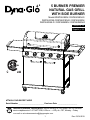
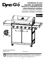
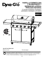
5 BURNER PREMIER
NATURAL GAS GRILL
WITH SIDE BURNER
Model #DGP552SSN / DGP552SSN-D /
DGP552CSN /DGP552CSN-D / DGP552GSN /
DGP552GSN-D / DGP552MSN / DGP552MSN-D
ATTACH YOUR RECEIPT HERE
Serial Number _____________________________ Purchase Date ______________________
Questions, problems, missing parts? Before returning to your retailer, call our customer
service department at 1-877-447-4768, 8:30 a.m. – 4:30 p.m., CST, Monday – Friday
or e-mail us at [email protected].
Français p.
XX
Español p.
XX
Français p. 30
Español p. 59

2
Assembler/Installer: This manual contains important information necessary for the proper
assembly and safe use of this appliance. Read and follow all warnings and instructions before
assembling and using this appliance. Leave these instructions with the consumer.
Consumer/User: Follow all warnings and instructions when using this appliance.
Retain these instructions for future reference.
TABLE OF CONTENTS
Safety Information ...................................................................................................................... 3
Package Contents ...................................................................................................................... 5
Hardware Contents .................................................................................................................... 6
Preparation ................................................................................................................................. 6
Assembly Instructions ................................................................................................................ 7
Operation Instructions ................................................................................................................. 19
Care and Maintenance ................................................................................................................. 21
Troubleshooting ........................................................................................................................... 24
Warranty ...................................................................................................................................... 26
Replacement Parts List .............................................................................................................. 27
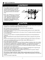
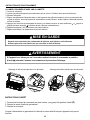
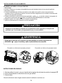
If you smell gas:
1. Shut off gas to the appliance.
2. Extinguish any open ame.
3. Open lid.
4. If odor continues, keep away from
the appliance and immediately call your
local re department.
1. Do not store or use gasoline or
other ammable liquids or vapors
in the vicinity of this or any other
appliance.
2. An LP (liquid propane) cylinder not
connected for use shall not be stored
in the vicinity of this or any other
appliance.
3. This grill is for outdoor use only
and shall not be used in a building,
garage, under overhangs or any other
enclosed area.
4. Do not leave a lit grill unattended.
Keep children and pets away from the
grill at all times.
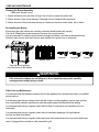
WARNING
DANGER

3
DANGER
• Do not use in an explosive atmosphere. Keep grill area clear and free from combustible
materials, gasoline and other ammable vapors and liquids.
Please read and understand this entire manual before attempting to assemble, operate or install
the product. If you have any questions regarding the product, please call customer service at:
1-877-447-4768, 8:30 a.m. – 4:30 p.m., CST, Monday – Friday.
SAFETY INFORMATION
This product and the fuels used to operate this product (liquid propane or natural gas), and
the products of combustion of such fuels, can expose you to chemicals including benzene,
which is known to the State of California to cause cancer and reproductive harm.
For more information go to www.p65Warnings.ca.gov
WARNING
CAUTION
• Never use charcoal or lighter uid with the grill.
• Do not use gasoline, kerosene or alcohol for lighting.
• This grill is not intended to be used in or installed on recreational vehicles and/or boats.
• Always open grill lid slowly and carefully as heat and steam trapped within the grill can burn
you severely.
• Never attempt to operate this grill using propane.
• Always employ a qualied service agency to install all necessary natural gas supply
plumbing, manual shutoff valve, and quick-connect ttings.

4
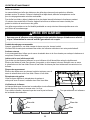
SAFETY INFORMATION
• Do not place the grill under overhead
combustible construction or awnings.
Minimum clearance from sides and
back of unit to combustible construction,
36 inches (914.4mm) from sides and
back.
NOTE: The installation must conform with
local codes or, in the absence of local
codes, with either the National Fuel Gas
Code, ANSI Z223.1/NFPA 54, Natural
Gas and Propane Installation Code,
CSA B149.1, or Propane Storage and
Handling Code, B149.2.
WARNING
36in
36in
914.4mm
914.4mm
•
Do not store or use gasoline or other ammable liquids or vapors in the vicinity of this or any other
appliance. Do not store ammables inside the cart of the grill.
• An LP cylinder shall not be stored in the vicinity of this or any other appliance.
• This grill is for use with natural gas only.
• Never attempt to attach this grill to the self-contained propane system of a boat, camper trailer,
motor home or house.
• Do not attempt to move the grill while it is lit or when it is hot. The casters should be locked when
not moving the grill.
• Do not use the grill unless it is completely assembled and all parts are securely fastened and
tightened.
• Keep all combustible items and surfaces at least 36 inches (91.44 cm) away from the grill at all
times.
• Do not touch metal parts of grill until it has completely cooled (about 45 minutes) to avoid burns,
unless you are wearing protective gear (pot holders, gloves, BBQ mittens, etc…).
• Do not alter this grill in any manner.
• Clean and inspect the hose before each use. If there is evidence of abrasion, wear, cuts, or leaks,
the hose must be replaced prior to operating the appliance. The replacement hose assembly will
be that which is specied by the manufacturer, listed in the repair parts list in this manual.
• Move gas hoses as far away as possible from hot surfaces and dripping hot grease. Never allow
the gas hose to touch heated surfaces.
• Keep the grill’s valve compartment, burners and circulating air passages clean. Inspect the grill
before each use. Do not obstruct the ow of gas or ventilation air.
• The use of alcohol, prescription or non-prescription drugs may impair the operator’s ability to
properly assemble or safely operate the grill.
• Do not leave a lit grill unattended. Keep children and pets away from the grill at all times.
• Do not place this grill on any type of tabletop surface. The grill should be placed on a at and level
surface.
• Do not use the grill in high winds.
CAUTION

5
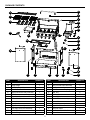
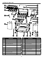
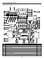
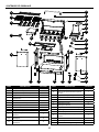
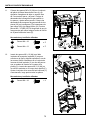
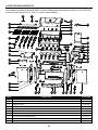
PACKAGE CONTENTS
D
A
B
C
E
F
G
H
I
J
X
Y
L
V
W
S
T
U
R
Q
K
O
A1
Z
P
M
N
A2
A
B
C
D
E
F
G
H
I
J
L
X
W
V
Y
K
M
N
A1 A2OZP
Q
R
S
T
U
PART DESCRIPTION QUANTITY
A Hood Handle 1
B Temp Gauge 1
C Grill Body Assembly 1
D Side Burner Rack 1
E Right Side Burner Body Assembly 1
F Side Burner 1
G Right Side Burner Control Panel 1
H Control Knob Bezel 1
I Control Knob 6
J Door Handle 2
K Right Door Assembly 1
L Cart Right Side Panel Assembly 1
M Locking Swivel Caster 2
N Non-Locking Swivel Caster 2
PART DESCRIPTION QUANTITY
O Bottom Panel Skirt Assembly 1
P Cart Left Side Panel Assembly 1
Q Left Door Assembly 1
R Quick Disconnect Coupling 1
S Heat Tent 5
T Cooking Grate 3
U Warming Rack 1
V Left Side Table Assembly 1
W Grease Pan 1
X Grease Cup 1
Y Upper Front Door Brace 1
Z Cart Rear Panel 1
A1 Cart Bottom Panel Shelf 1
A2 Natural Gas Hose Holder 2

6
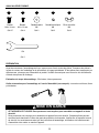
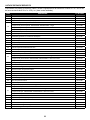
HARDWARE CONTENTS
M6x16
Bolt
Qty. 37
M6
Spring Washer
Qty. 2
M4x12
Bolt
Qty. 4
M6
Plain Washer
Qty. 2
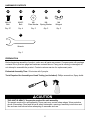
PREPARATION
Before beginning assembly of product, make sure all parts are present. Compare parts with package
contents list on previous page and hardware contents above. If any part is missing or damaged, do
not attempt to assemble the product. Contact customer service for replacement parts.
Estimated Assembly Time: 50 minutes with 2 people.
Tools Required for Assembly and Leak Testing (not included): Phillips screwdriver, Spray bottle
CAUTION
THIS UNIT IS HEAVY. Two people required for safe assembly.
Two people required for safe assembly. Some parts may contain sharp edges. Wear protective
gloves if necessary. Read and follow all safety statements, warnings, assembly instructions and
use and care instructions before attempting to assemble and use.
CCAA BB DD
FF
M6
Wingnut
Qty. 2
EE
Wrench
Qty. 1
BB
AA
DDCC
M6
Spring
Qty. 2
M6
Qty. 2
M4x10
Bolt
Qty. 2
M6x16
Bolt
Qty. 37
Washer
EE
M6
Wingnut
Qty. 2
Washer
FF
Qty. 1
Wrench
BB
AA
DDCC
M6
Spring
Qty. 2
M6
Qty. 2
M4x10
Bolt
Qty. 2
M6x16
Bolt
Qty. 37
Washer
EE
M6
Wingnut
Qty. 2
Washer
FF
Qty. 1
Wrench
BB
AA
DDCC
M6
Spring
Qty. 2
M6
Qty. 2
M4x10
Bolt
Qty. 2
M6x16
Bolt
Qty. 37
Washer
EE
M6
Wingnut
Qty. 2
Washer
FF
Qty. 1
Wrench
BB
AA
DDCC
M6
Spring
Qty. 2
M6
Qty. 2
M4x10
Bolt
Qty. 2
M6x16
Bolt
Qty. 37
Washer
EE
M6
Wingnut
Qty. 2
Washer
FF
Qty. 1
Wrench
BB
AA
DDCC
M6
Spring
Qty. 2
M6
Qty. 2
M4x10
Bolt
Qty. 2
M6x16
Bolt
Qty. 37
Washer
EE
M6
Wingnut
Qty. 2
Washer
FF
Qty. 1
Wrench

7
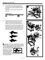
ASSEMBLY INSTRUCTIONS
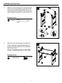
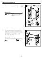
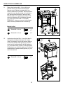
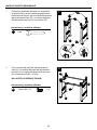
1. Attach the two locking swivel casters (M) and
the two non-locking swivel casters (N) to the
cart left side panel assembly (P) and the cart
right side panel assembly (L) with wrench (FF).
Hardware Used
Wrench
2. Attach the cart left side panel assembly (P)
and the cart right side panel assembly (L)
to the cart bottom panel shelf (A1) with four
M6x16 bolts (AA).
DO NOT TIGHTEN BOLTS AT THIS TIME.
Hardware Used
AA
M6x16 Bolt
x 4
2
FF
1
L
P
N
M
Wrench
x1
FF
Hardware Used
FF
M
N
L
P
FF
BB
AA
DDCC
M6
Spring
Qty. 2
M6
Qty. 2
M4x10
Bolt
Qty. 2
M6x16
Bolt
Qty. 37
Washer
EE
M6
Wingnut
Qty. 2
Washer
FF
Qty. 1
Wrench
P
L
AA
A1

8
ASSEMBLY INSTRUCTIONS
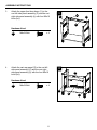
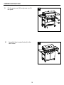
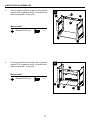
3. Attach the upper front door brace (Y) to the
cart left side panel assembly (P) and the cart
right side panel assembly (L) with four M6x16
bolts (AA).
4. Attach the cart rear panel (Z) to the cart left
side panel assembly (P) and the cart right
side panel assembly (L) with the four M6x16
bolts (AA).
3
4
Hardware Used
Hardware Used
AA
AA
M6x16 Bolt
M6x16 Bolt
x 4
x 4
BB
AA
DDCC
M6
Spring
Qty. 2
M6
Qty. 2
M4x10
Bolt
Qty. 2
M6x16
Bolt
Qty. 37
Washer
EE
M6
Wingnut
Qty. 2
Washer
FF
Qty. 1
Wrench
BB
AA
DDCC
M6
Spring
Qty. 2
M6
Qty. 2
M4x10
Bolt
Qty. 2
M6x16
Bolt
Qty. 37
Washer
EE
M6
Wingnut
Qty. 2
Washer
FF
Qty. 1
Wrench
L
AA
P
P
Z
L
Y
AA

9
ASSEMBLY INSTRUCTIONS
5. Attach the bottom panel skirt assembly (O) to
the cart bottom shelf (A1), cart left side panel
assembly (P) and the cart right side panel
assembly (L) with four M6x16 bolts (AA).
Tighten ALL bolts securely from Step 2.
5
Hardware Used
AA
M6x16 Bolt
x 4
BB
AA
DDCC
M6
Spring
Qty. 2
M6
Qty. 2
M4x10
Bolt
Qty. 2
M6x16
Bolt
Qty. 37
Washer
EE
M6
Wingnut
Qty. 2
Washer
FF
Qty. 1
Wrench
L
P
O
AA
A1
J
AA
K
Q
AA
M6x16
Bolt x4
AA
Hardware Used
6. Attach the door handle (J) to the left door
assembly (Q) and the right door assembly (K)
with four M6x16 bolts (AA).
6
Hardware Used
AA
M6x16 Bolt
x 4
BB
AA
DDCC
M6
Spring
Qty. 2
M6
Qty. 2
M4x10
Bolt
Qty. 2
M6x16
Bolt
Qty. 37
Washer
EE
M6
Wingnut
Qty. 2
Washer
FF
Qty. 1
Wrench
J
K
Q
AA

10
ASSEMBLY INSTRUCTIONS
7. Insert the bottom hinge pin of the cart bottom
panel skirt (O) into the lower hole on the left
door assembly (Q), then press the upper door
spring hinge pin into the hole on the cart left
side panel assembly (P) as shown.
Repeat with the right door assembly (K).
7
Q
K
O
L
P
8. Attach the hood handle (A) to the grill body
assembly (C) with two M6 wing nuts (EE),
two M6 spring washers (DD) and two M6
plain washers (CC).
8
Hardware Used
CC M6 Plain Washer x 2
DD M6 Spring Washer x 2
EE M6 Wingnut x 2
BB
AA
DDCC
M6
Spring
Qty. 2
M6
Qty. 2
M4x10
Bolt
Qty. 2
M6x16
Bolt
Qty. 37
Washer
EE
M6
Wingnut
Qty. 2
Washer
FF
Qty. 1
Wrench
BB
AA
DDCC
M6
Spring
Qty. 2
M6
Qty. 2
M4x10
Bolt
Qty. 2
M6x16
Bolt
Qty. 37
Washer
EE
M6
Wingnut
Qty. 2
Washer
FF
Qty. 1
Wrench
BB
AA
DDCC
M6
Spring
Qty. 2
M6
Qty. 2
M4x10
Bolt
Qty. 2
M6x16
Bolt
Qty. 37
Washer
EE
M6
Wingnut
Qty. 2
Washer
FF
Qty. 1
Wrench
A
CC
DD
EE
C

11
ASSEMBLY INSTRUCTIONS
9. Remove pre-assembled wing nut and plain
washer from the temp gauge (B), then attach
the temp gauge (B) to the grill body assembly
(C). Secure the temp gauge (B) with wing nut
and plain washer removed earlier in this step.
9
B
C
10. Carefully place the grill body (C) onto cart
left side panel assembly (P) and cart right
side panel assembly (L). Adjust the grill body
(C) so that the holes in the grill body (C) are
aligned with holes in the tabs of cart left side
panel assembly (P) and cart right side panel
assembly (L).
Note: Make sure the natural gas hose is inside
the cart. Secure the grill body (C) with four
M6X16 bolts (AA).
10
Hardware Used
AA
M6x16 Bolt
x 4
BB
AA
DDCC
M6
Spring
Qty. 2
M6
Qty. 2
M4x10
Bolt
Qty. 2
M6x16
Bolt
Qty. 37
Washer
EE
M6
Wingnut
Qty. 2
Washer
FF
Qty. 1
Wrench
AA
C
L

12
5mm
5mm
5mm
ASSEMBLY INSTRUCTIONS
12. Insert two M6x16 bolts (AA) in left side of grill
body (C) as shown, leaving 5mm of threads
exposed. Align key hole in left side table
assembly (V) with the two bolts just inserted in
the grill body (C), and insert two M6x16 bolts
(AA) in the remaining holes in the grill body (C).
Adjust left side table assembly (V) correctly,
then tighten all bolts.
Hardware Used
AA
M6x16 Bolt
x 4
BB
AA
DDCC
M6
Spring
Qty. 2
M6
Qty. 2
M4x10
Bolt
Qty. 2
M6x16
Bolt
Qty. 37
Washer
EE
M6
Wingnut
Qty. 2
Washer
FF
Qty. 1
Wrench
AA
V
C
12
11. Pre-assemble two M6x16 bolts (AA) onto the
cart right side panel assembly (L) and do not
tighten them. Make sure to leave a 5mm gap
between the bolt and the panel. Hang the
natural gas hose bracket onto the bolts and
tighten the two bolts. Put the two-piece natural
gas hose holders (A2) on the hose. Attach the
natural gas hose (A2) to the bottom shelf (A1)
with two M4x12 bolts (BB). NOTE: Make sure
the natural gas hose exits through the hole in
the cart rear panel (Z).
11
Hardware Used
AA
BB
M6x16 Bolt
M4x12 Bolt
x 2
x 2
BB
AA
DDCC
M6
Spring
Qty. 2
M6
Qty. 2
M4x10
Bolt
Qty. 2
M6x16
Bolt
Qty. 37
Washer
EE
M6
Wingnut
Qty. 2
Washer
FF
Qty. 1
Wrench
AA
A2
A2
A1
A2
BB
L
Z
BB
AA
DDCC
M6
Spring
Qty. 2
M6
Qty. 2
M4x10
Bolt
Qty. 2
M6x16
Bolt
Qty. 37
Washer
EE
M6
Wingnut
Qty. 2
Washer
FF
Qty. 1
Wrench

13
5mm
5mm
13
14
ASSEMBLY INSTRUCTIONS
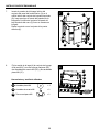
13. Attach the right side burner control panel (G)
to the right side burner body assembly (E)
with three M6x16 bolts (AA).
Hardware Used
Hardware Used
AA
AA
M6x16 Bolt
M6x16 Bolt
x 3
x 4
BB
AA
DDCC
M6
Spring
Qty. 2
M6
Qty. 2
M4x10
Bolt
Qty. 2
M6x16
Bolt
Qty. 37
Washer
EE
M6
Wingnut
Qty. 2
Washer
FF
Qty. 1
Wrench
BB
AA
DDCC
M6
Spring
Qty. 2
M6
Qty. 2
M4x10
Bolt
Qty. 2
M6x16
Bolt
Qty. 37
Washer
EE
M6
Wingnut
Qty. 2
Washer
FF
Qty. 1
Wrench
G
AA
E
AA
M6x16
Bolt x3
AA
Hardware Used
AA
G
E
14. Insert two M6x16 bolts (AA) in right side of grill
body (C) as shown, leaving 5mm of threads
exposed. Align key hole in right side table
assembly (E) with the two bolts just inserted in
the grill body (C), and insert two M6x16 bolts
(AA) in the remaining holes in the grill body (C).
Adjust right side table assembly (E) correctly,
then tighten all bolts.
E
AA
C

14
WARNING: IT IS VERY IMPORTANT TO CHECK
AND ENSURE THAT EACH AND EVERY BURNER
IS FULLY ENGAGED WITH THE ADJACENT VALVE
ORIFICE BEFORE COMPLETING STEP 16.
FAILURE TO DO SO MAY
RESULT IN FIRE OR
EXPLOSION, POSSIBLY
CAUSING SERIOUS
INJURY OR DEATH. REFER TO MAINTENANCE
SECTION INSTRUCTIONS TO PROPERLY CHECK
THE ENGAGEMENT.
ASSEMBLY INSTRUCTIONS
15
16
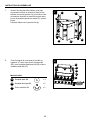
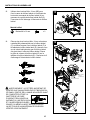
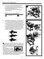
15. Use two M4x12 bolts (BB) to assemble the
side burner valve and the side burner control
knob bezel (H) to the right side burner control
panel (G).
Assemble the ignition wire to the side burner
electrode.
16. Disassemble two M4x10 bolts and two M4
washers that are pre-assembled on the side
burner (F) and use them to assemble the
side burner (F) on the right side burner table
assembly (E). Make sure the side burner orice
is placed into the gas inlet tube of side burner.
Place the side burner cooking grate (D) on the
right side burner table assembly (E). Assemble
the ignition wire to the side burner electrode.
Incorrect
Incorrect
Correct
Hardware Used
BB
M4x12 Bolt
x 2
BB
G
H
BB
AA
DDCC
M6
Spring
Qty. 2
M6
Qty. 2
M4x10
Bolt
Qty. 2
M6x16
Bolt
Qty. 37
Washer
EE
M6
Wingnut
Qty. 2
Washer
FF
Qty. 1
Wrench
F
GL1B
SC U
R
1/2PSI
GL1B
SC U
R
1/2PSI
GL1B
SC U
R
1/2PSI
Incorrect
Incorrect
Correct
D
F
F
GL1B
SC U
R
1/2PSI
GL1B
SC U
R
1/2PSI
GL1B
SC U
R
1/2PSI
Incorrect
Incorrect
Correct
D
F
F
GL1B
SC U
R
1/2PSI
GL1B
SC U
R
1/2PSI
GL1B
SC U
R
1/2PSI
Incorrect
Incorrect
Correct
D
F
F
GL1B
SC U
R
1/2PSI
GL1B
SC U
R
1/2PSI
GL1B
SC U
R
1/2PSI
Incorrect
Incorrect
Correct
D
F
F
E
F
D
E
2 washers
previously
disassembled
2 bolts previously
disassembled

15
ASSEMBLY INSTRUCTIONS
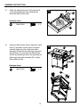
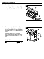
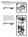
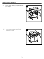
17. Put ve heat tents (S) in place over each
burner.
17
18. Put three cooking grates (T) and one warming
rack (U) in place.
18
S
U
T

16
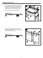
ASSEMBLY INSTRUCTIONS
19. Put the grease pan (W) and grease cup (X)
into place.
19
20. Assemble the six control knobs (I) to the
valve stems.
20
W
X
I

17
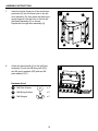
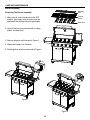
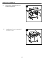
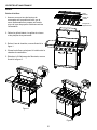
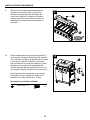
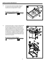
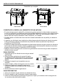
ASSEMBLY INSTRUCTIONS
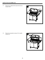
Front View Rear View
Fully Assembled
• The quick disconnect socket (R) and supply gas line must be installed by a qualied service
agency. The supply connection must be made in accordance with local codes or, in the absence
of local codes, with either the National Fuel Gas Code, ANSI Z223.1/NFPA 54, in the USA, of the
Natural Gas and Propane Installation Code, CSA B149.1, in Canada.
• A properly sized manual shut-off valve must be installed between the frill and the gas supply piping.
• The grill and its individual shut-off valve must be disconnected from the gas supply piping system
during any pressure testing of that system at test pressures in excess of 0.5 PSI (3.5 kPa).
• The grill must be isolated from the gas supply piping system by closing its individual manual shut-
off valve during any pressure testing of the gas supply piping system at test pressures equal to or
less than 0.5 PSI (3.5 kPa).
• Always connect the exible gas supply hose to the gas supply before opening the manual shutoff
valve.
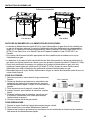
1. Ensure that the natural gas shut-off valve is closed.
2. Remove the protective rubber caps from the plug
and sleeve ends of the quick disconnect ttings.
Check that the ttings are clean.
3. Retract the sleeve on the coupling as illustrated.
4. Insert the plug and release the sleeve as illustrated.
5. Push the plug into the sleeve until the sleeve snaps
forward to lock the plug in the coupling.
6. Open the natural gas shut-off valve.
1. Close natural gas supply at shut-off valve.
2. Push the sleeve back and gently pull out the plug.
3. Replace the protective rubber caps on the plug and
sleeve ends of the quick disconnect couplings.
CONNECTING THE GRILL TO THE NATURAL GAS SUPPLY
TO CONNECT:
TO DISCONNECT:
R
Retract Sleeve
Release Sleeve

18
ASSEMBLY INSTRUCTIONS
CHECKING FOR LEAKS
After all connections are made, check all connections and ttings on the natural gas quick connector,
gas hose and manifold for leaks with a water and soap solution.
To prevent re or explosion while testing for a leak:
• Always perform leak test prior to lighting the grill.
• Do not smoke while testing for a leak.
• Always perform leak tests outdoors in a well-ventilated area.
• Do not use any source of ame while testing for leaks.
• Do not use the grill until any and all leaks are corrected.
• If you are unable to correct a leak, close the natural gas shut-off and call a gas appliance service
agency.
PERFORM LEAK TEST
• Prepare leak test solution by combining 1 part liquid dish soap with 3 parts water.
Total solution required is approximately 2 - 3 ounces (70 - 90 ml).
Put leak test solution in a spray bottle.
• Ensure all control knobs are in the ‘OFF’ position.
• Connect the gas hose to the gas supply.
• Open the gas shut-off valve.
• Spray leak test solution on all gas carrying connections and ttings. Presence of bubbles at areas
of applied test solution indicates a gas leak. If leaks are detected or you smell or hear gas, shut off
the gas supply valve immediately and repair or replace the defective part. Do not use the grill until all
leaks are corrected.
ALL INSTRUCTIONS AND SAFEGUARDS ON THIS PAGE MUST BE FOLLOWED TO
PREVENT FIRE, DAMAGE AND/OR INJURY.
In the connection process, make sure:
• The gas supply hose does not come in contact or remain in contact with the rebox.
Only use the hose assembly provided! If a replacement is necessary, please call
our customer service center. Do not use replacement parts that are not intended for this grill.
WARNING
WARNING
CAUTION

19
OPERATION INSTRUCTIONS
Lighting The Grill
Before rst use:
Remove all hangings or plastic straps, if present. Before you cook on your new gas grill, it is important
to clean your grill with heat. To do this, operate the grill for approximately 15 minutes with the lid closed
and the control knob in the highest position. This will clean the internal parts by burning off any residue
and odor from the manufacturing process.
WARNING
Do not lean over grill when lighting. Read instructions before lighting. Do not put pots on the
sear side burner. Using pots on the sear side burner will result in high carbon monoxide levels.
CAUTION
If the ame extinguishes accidentally during ignition or operation, immediately TURN OFF the
natural gas shut-off valve and then TURN OFF the control knob.
1. Check that the control knobs are in the
OFF position.
2. Open natural gas supply at shut-off valve.
3. Open the lid during the lighting process.
4. Depress and turn the control knob counter-clockwise from the OFF position, past the ignite
position, to the HIGH position. You may need to repeat this several times to ignite the burner.
If ignition does not occur in 5 seconds, turn the control knob(s) to the OFF position, wait 5 minutes, and
repeat the lighting procedure.
If the burner still does not light, check that the natural gas shut-off valve is open and follow the match
lighting instructions. Check the Troubleshooting Guide on page 24 for more information.

20
OPERATION INSTRUCTIONS
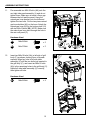
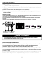
LIGHTING THE GRILL WITH A MATCH
1. Open the lid.
2. Insert a match in the end of the match holder that is installed on the inside of the cabinet door.
3. Light the match.
4. Immediately place the lit match through the spaces in the grill gates near the ports of the burner
between the heat tents as shown. Make sure the lit match is close to the burner ports.
5. Press in the control knob that operates the burner and rotate counter-clockwise to
High
position and burner should light immediately.
6. Repeat 2~5 steps to lighting the remaining burners.
7. Adjust burners to desired cooking settings.
CAUTION
Make sure all burners controls are off except for the burner being lit and the
burners that have been lit.
Main Burner Match Lighting Side Burner Match Lighting
If ignition does not occur in 5 seconds, turn the control knob(s) to “ ” OFF position, wait 5
minutes, and repeat the lighting procedure.
WARNING
SHUTDOWN INSTRUCTIONS
1. Turn control knobs clockwise to the O OFF position.
2. Close natural gas shut-off valve.
3. Close lid.
Turn off natural gas shut-off valve when appliance is not in use.
La page est en cours de chargement...
La page est en cours de chargement...
La page est en cours de chargement...
La page est en cours de chargement...
La page est en cours de chargement...
La page est en cours de chargement...
La page est en cours de chargement...
La page est en cours de chargement...
La page est en cours de chargement...
La page est en cours de chargement...
La page est en cours de chargement...
La page est en cours de chargement...
La page est en cours de chargement...
La page est en cours de chargement...
La page est en cours de chargement...
La page est en cours de chargement...
La page est en cours de chargement...
La page est en cours de chargement...
La page est en cours de chargement...
La page est en cours de chargement...
La page est en cours de chargement...
La page est en cours de chargement...
La page est en cours de chargement...
La page est en cours de chargement...
La page est en cours de chargement...
La page est en cours de chargement...
La page est en cours de chargement...
La page est en cours de chargement...
La page est en cours de chargement...
La page est en cours de chargement...
La page est en cours de chargement...
La page est en cours de chargement...
La page est en cours de chargement...
La page est en cours de chargement...
La page est en cours de chargement...
La page est en cours de chargement...
La page est en cours de chargement...
La page est en cours de chargement...
La page est en cours de chargement...
La page est en cours de chargement...
La page est en cours de chargement...
La page est en cours de chargement...
La page est en cours de chargement...
La page est en cours de chargement...
La page est en cours de chargement...
La page est en cours de chargement...
La page est en cours de chargement...
La page est en cours de chargement...
La page est en cours de chargement...
La page est en cours de chargement...
La page est en cours de chargement...
La page est en cours de chargement...
La page est en cours de chargement...
La page est en cours de chargement...
La page est en cours de chargement...
La page est en cours de chargement...
La page est en cours de chargement...
La page est en cours de chargement...
La page est en cours de chargement...
La page est en cours de chargement...
La page est en cours de chargement...
La page est en cours de chargement...
La page est en cours de chargement...
La page est en cours de chargement...
La page est en cours de chargement...
La page est en cours de chargement...
La page est en cours de chargement...
-
 1
1
-
 2
2
-
 3
3
-
 4
4
-
 5
5
-
 6
6
-
 7
7
-
 8
8
-
 9
9
-
 10
10
-
 11
11
-
 12
12
-
 13
13
-
 14
14
-
 15
15
-
 16
16
-
 17
17
-
 18
18
-
 19
19
-
 20
20
-
 21
21
-
 22
22
-
 23
23
-
 24
24
-
 25
25
-
 26
26
-
 27
27
-
 28
28
-
 29
29
-
 30
30
-
 31
31
-
 32
32
-
 33
33
-
 34
34
-
 35
35
-
 36
36
-
 37
37
-
 38
38
-
 39
39
-
 40
40
-
 41
41
-
 42
42
-
 43
43
-
 44
44
-
 45
45
-
 46
46
-
 47
47
-
 48
48
-
 49
49
-
 50
50
-
 51
51
-
 52
52
-
 53
53
-
 54
54
-
 55
55
-
 56
56
-
 57
57
-
 58
58
-
 59
59
-
 60
60
-
 61
61
-
 62
62
-
 63
63
-
 64
64
-
 65
65
-
 66
66
-
 67
67
-
 68
68
-
 69
69
-
 70
70
-
 71
71
-
 72
72
-
 73
73
-
 74
74
-
 75
75
-
 76
76
-
 77
77
-
 78
78
-
 79
79
-
 80
80
-
 81
81
-
 82
82
-
 83
83
-
 84
84
-
 85
85
-
 86
86
-
 87
87


Dyna-Glo DGP552SSN-D Mode d'emploi
- Catégorie
- Barbecues
- Taper
- Mode d'emploi
dans d''autres langues
Documents connexes
-
Dyna-Glo DGP552CSP-D Manuel utilisateur
-
-
-
-
-
Dyna-Glo Dyna-Glo DG13GT-D Stainless Steel Grill Topper Manuel utilisateur
-
-
-
-