DE LONGHI EX CST Series Le manuel du propriétaire
- Taper
- Le manuel du propriétaire


EX CST Series
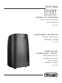
PORTABLE AIR CONDITIONER
Instructions for use. Keep these instructions
ELECTRIC
CHARACTERISTICS
115 V~ 60 Hz
CONDITIONNEUR D’AIR PORTATIF
Mode d’emploi . Conservez cette notice
CARACTÉRISTIQUES
ÉLECTRIQUES
115 V~ 60 Hz
SISTEMA DE AIRE
ACONDICIONADO
PORTÁTIL
Repase y guarde estas instrucciones.
Lea cuidadosamente este instructivo
antes de usar su aparato.
CARACTERISTICAS
ELECTRICAS:
115 V~ 60 Hz

2
pag. 4 pag. 15 pag. 27
ES
FR
EN

3
B4
B3
B5
B6
B7
B9
B8
A11
A1
A8
B2 B1
B10
A2
A3
A4
A5
A6
A7
A9
A10

4
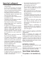
Important safeguard
•
Use this appliance only as described in this
instruction manual.
As with any electrical appliance, the instructions
aim to cover as many situations as possible.
Caution and common sense should be used when
operating and installing this air conditioner.
•
This appliance has been manufactured to cool
and dehumidify domestic environments and
must not be used for other purposes.
•
It is dangerous to alter or modify the unit's
characteristics in any way.
•
The appliance must be installed in accordance
with the relevant national legislation.
•
Should repairs be necessary, contact the nearest
authorized Repair Service Center. Unauthorized
servicing can be dangerous.
•
The appliance is not intended for use by persons
(including children) with reduced physical,
sensory or mental capabilities, or lack of
experience and knowledge, unless they have
been given supervision or instruction concerning
use of the appliance by a person responsible for
their safety.
Children should be supervised to ensure that
they do not play with the appliance.
•
If the power cable is damaged, it must be
replaced by the manufacturer or an authorized
technical service centre in order to avoid all risk.
•
Always ensure the appliance is plugged into a
grounded 3-prong outlet. If you have any doubts
check with a qualified electrician.
•
Do not use extension cables.
•
Before cleaning or maintenance operations,
always unplug the unit from the outlet.
•
Do not pull on or place strain on the power cord
when moving the appliance.
•
The appliance should not be installed where the
atmosphere may contain combustible gases, oil
or sulphur, or near heat sources.
•
Do not rest hot or heavy objects on the appliance.
•
Clean the filters at least once a week.
•
Avoid using heaters near the unit.
•
The unit should be transported in a vertical
position. If this is not possible secure the unit at
an angle, do not lie it horizontally.
•
Before transporting the unit, drain the unit.
After transportation, wait at least 6 hours before
switching the unit on.
•
The packaging materials can be recycled. You
are therefore recommended to place them in
the special containers for differentiated waste
collection.
•
This appliance is fitted with a special safety
device. When the compressor switches off, this
device prevents it from switching on again for at
least 3 minutes.
•
WARNING: Changes or modifications not
expressly approved by the party responsible for
compliance could void the user's authority to
operate the equipment.
Specific warnings for appliances with R410A
refrigerant gas
R410A is a refrigerant that complies with
European ecological standards; nevertheless, it is
recommended not to pierce the cooling circuit of
the machine. At the end of its useful life, deliver the
appliance to a special waste collection centre for
disposal. This hermetically sealed system contains
fluorinated greenhouse gases.
ENVIRONMENTAL INFORMATION:
This unit contains fluorinated greenhouse gases
covered by the Kyoto Protocol.
Maintenance and disposal must be carried out by
qualified personnel only (R410A, GWP=2088).
Save these instructions
This product is for household only

5
INTRODUCTION
Thank you for choosing a De’Longhi product. Please take a few
moments to read the instructions to avoid risks or damage to the
appliance.
DESCRIPTION
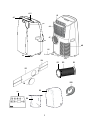
Description of the appliance (see page 3 - A)
A1
air outlet flap
A2
control panel
A3
handles
A4
castors
A5
BioSilver filter
A6
air intake grille
A7
air exhaust hose housing
A8
air intake grille
A9
power cable
A10
drainage hose with cap
A11
CST remote control compartment
Description of the accessories (see page 3 - B)
B1
adapter for window bracket
B2
air exhaust hose
B3
hose adaptor
B4
additional window bracket
B5
window bracket with wing nut
B6
window bracket cap
B7
CST (Cool Surround Tecnology) remote control
B8
end of season accessories bag (*not on all models)
B9
end of season dust cover
(*not on all models)
B10
stripping foam
ELECTRICAL CONNECTION
Before plugging the appliance into the outlet, check that:
•
The outlet’s power supply corresponds to the value
indicated on the rating label on the back of the appliance.
•
The outlet and electrical circuit are adequate for the
appliance.
•
The outlet is a 3-hole grounded outlet
. If this is not
the case, you must choose another outlet. Failure to follow
these important safety instructions absolves the manufac-
turer of all liability.
If it becomes necessary, the power cable must be re-
placed by a qualified professional only.
USE
The instructions below will enable you to prepare your air con-
ditioner for operation as efficiently as possible. Before use, make
sure the air intake and air outlet flap are unobstructed.
Please note:
This appliance is provided with an auto-evapora-
tion feature for condensate removal during cooling and dehu-
midifying modes.
AIR
CONDITIONING
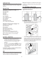
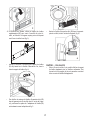
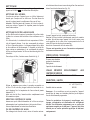
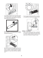
INSTALLATION
For optimal results see the figures below for the
suggested minum distances.
DOUBLE-HUNG
WINDOW
•
Place the window bracket (B5) in the window sill, extend
the bracket fully within the window frame (fig. 1).
•
Fix the bracket by the wing nut (fig. 2). Attach the provided
stripping foam (
B10
) to the top of the window bracket and
then lower the window onto the bracket. (Should the win-
dow bracket be too large for the window the plastic can be
cut with a saw by a qualified professional.)
1
20 in
50 cm
20 in
50 cm
20 in
50 cm
20 in
20 in
50 cm
50 cm
32 in
36 in
90 cm
80 cm
2

6
14
C6
C7
C8
C13
C9
10
11
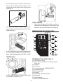
•
If the windows are large, use additional window bracket
(B4) to cover your window aperture, extending it to the
required length, then blocking it with the locking wing nut
supplied (fig. 3).
•
Insert and lock the accessory for window bracket (B1) al-
ready assembled to the air exhaust hose, into the slot of the
window bracket (fig. 4).
SLIDING
WINDOWS
•
Thanks to the locking wing nut, it’s possible to use the win-
dow bracket also for sliding windows. Position the hole of the
bracket so to allow a correct installation of the exhaust hose.
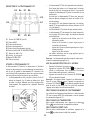
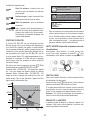
OPERATING FROM THE CONTROL PANEL
C17 C16 C15
C C1
C3
•
In order to facilitate the fitting of the air exhaust hose (B2)
in the relevant housing located on the rear side of the ap-
pliance, position the hose adapter‘s tabs (B3) in a vertical
axis as shown in fig. 5 .
•
Fit the air exhaust hose (B2) in the relevant housing located
on the rear side of the appliance (fig . 6).
C
C C2
C5
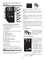
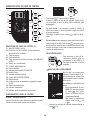
DESCRIPTION OF THE CONTROL PANEL (C)
C1.
ON/STAND-BY (on/off) key
C2.
Function selection key MODE (air conditioning, dehumidi-
fying, fan)
C3.
Increase key
C4.
Decrease key
C5.
Fan speed selection key
(MIN/MED/MAX/AUTO)
C6.
Air conditioning symbol
C7.
Dehumidifying symbol
C8.
Fan symbol
C9.
ECO REAL FEEL symbol/status indicator
C10.
Swing symbol
C11.
Fan speed indicator
C12.
ARCTIC WHISPER EXTREME symbol
5
C12
C4
3
4
6

7
C13.
Alarm symbol
C14.
Set temperature values, programmed on/off timer
C15.
Timer symbol
C16.
Timer indicator
C17.
Selected temperature scale indicator
CONTROL PANEL OPERATION
TURNING THE APPLIANCE ON AND OFF
Insert the plug in the socket. Two dashes appear on the display
indicating that the appliance is in stand-by.
Touch the
(C1) key to turn ON the appliance.
The flap A1 will open after few seconds. When the appliance
comes ON the last function set before it was shut off is activated.
Please note:
If start-up is not continued, after a few minutes
the display light dims in order to reduce energy consumption.
To turn the appliance off, touch the
key and then pull the
plug.
Please note:
Never turn off the air conditioner by simply pulling
the plug. Touch the
key in order to put your air conditioner in
stand-by and wait a few minutes before pulling the plug. In this
manner, the appliance can perform the operating status checks.
MODES SELECTION
To select the desired operating
mode, touch repeatedly the MODE
key (C2) until
the desired function
is selected.
AIR CONDITIONING MODE
This is ideal for hot and humid
weather when the room needs to
be cooled. This function also helps
dehumidify the air.
To correctly set this mode:
•
Touch repeatedly the
MODE
key (C2) until the air condition-
ing symbol appears. The
display will show the desired
temperature.
•
To change the temperature to
be reached, touch the
(C3)
or (C4) key.
•
Select the desired fan speed by touching the
(C5) key.
The speeds available are:
Minimum speed
: when maximum silent
operation is desired.
Medium speed
: when the noise level needs to
be low but with a good comfort level.
Maximum speed
: to reach the desired
temperature as soon as possible.
Auto
:
the appliance automatically chooses the
best fan speed based on the temperature select
ed and the environmental conditions.
DEHUMIDIFYING MODE
This is ideal for reducing humidity in
the room (spring and autumn, damp
rooms, rainy periods, etc). For this
type of use, the appliance must be set
up as for air conditioning mode. That
is, the air exhaust hose (B2) must be
fitted to the appliance to allow the
humidity to be discharged outside.
To correctly set this mode:
•
Touch repeatedly the
MODE
key (C2) until the dehumidify-
ing symbol appears.
•
The appliance will automatically choose the best air
flow.
FAN MODE
When using this mode, the air ex-
haust hose (B2) does not need to be
attached to the appliance.
To correctly set this mode:
•
Touch repeatedly the MODE
(C2) key until the fan
sym-
bol appears.
•
Select the desired air flow by pressing
button (C5).
The air flows available are:
Minimum air flow:
when most silent operation
is desired.
Medium air flow
: when the noise level needs to
be low but with a good comfort level.
Maximum air flow
: for maximum performance.

8
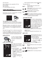
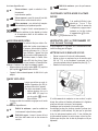
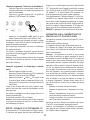
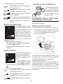
SELECT THE TEMPERATURE SCALE DESCRIPTION OF THE CST REMOTE CONTROL
The temperature can be dis-
played in °C or °F. To change the
temperature unit of measure
touch both
the
increase
(C3) or decrease C4) keys for
about 10 sec.
D9
D5 D6 D7 D8
D10
D1
OPERATING FROM THE CST (Cool Surround
Tecnology) REMOTE CONTROL
The CST remote controller is based on Bluetooth® Low Energy
communication with the Pinguino.
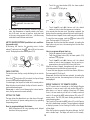
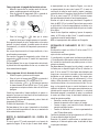
INSERTING OR REPLACING THE BATTERIES
•
Remove the cover on the rear of the remote control.
•
Insert or replace the batteries with two new LR6 “AA” 1.5V
batteries, inserting them correctly (see the instructions in-
side the battery compartment) (fig. 7).
•
Replace the cover.
If the remote control unit is replaced or discarded, the batter-
ies must be removed and disposed of in accordance with current
legislation as they are harmful to the environment.
Do not mix old and new batteries.
Do not mix alkaline, standard (carbon-zinc) or rechargeable bat-
teries. Do not dispose of batteries in fire. Batteries may explode
or leak. If the remote control is not be used for a certain length of
time, remove the batteries. Use only battery within the expired
date.
D2 D3 D4
D1
ON/STAND-BY (on/off) button
D2
MODE button
D3
Decrease button
D4
Increase button
D5
Swing button (flap swing)
D6
ARCTIC WHISPER EXTREME button
D7
Air flow button
D8
Timer button
D9
ECO REAL FEEL button
D10
Indication LED
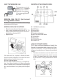
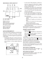
USING THE CST REMOTE CONTROL
The CST remote control senses temperature and humidity like a
thermostat for a personalized custom cool around you. By keep-
ing the CST remote nearby, it will track humidity and tempera-
ture around you making sure you’ll always enjoy your desired
comfort.
•
The remote control must be no more than about 33 ft (10
meters) away from the appliance (fig. 8) (even in non line
of sight). The maximum range may be lower depending
on the environment. It belongs to Bluetooth class 2 device
class.
max 33ft~
8
7

9
•
The CST remote control must be handled with care. Do not
drop it or expose it to direct sunlight or sources of heat. It is
advisable to keep the CST remote control placed on a table
or a flat surface. Do not hold the CST remote control in your
hand for long time to avoid altering the reading of the sen-
sors.
•
The CST sensors are also disabled if the CST remote control is
positioned at a distance less than 3.3ft (1 m) from the unit.
•
The CST remote control is equipped with touch sensitive
buttons.
•
The CST remote control is equipped with a dual color LED
(D10) (white/red). White indications are used for:
-
signaling the touching of each button with 3 fast flashes
-
it blinks every 30 seconds for data transmission
-
signaling the entering of pairing phase with periodic
blinking
-
signaling the battery status is “good”
•
The same indications but in red color mean that the batter-
ies are starting to be exhausted.
Please note:
The remote control can be safely stored in the ap-
propriate compartment (A11).
TURNING THE APPLIANCE ON/OFF
•
Plug into the outlet.
•
Touch the
ON/STAND-BY button (D1). When turned ON,
the air conditioner starts operating in the same mode as
when it was turned off.
•
Touch the
ON/STAND-BY button (D1) again to switch the
appliance off.
Please note:
Never switch the appliance off by removing the plug.
Always switch it off by touching the
ON/STAND-BY button (D1)
and waiting for a few minutes before removing the plug. Only in
this way the appliance will perform its standard checks.
SELECTING THE OPERATING MODES
The operating modes available on the CST remote control
through the MODE button (D2) correspond to those on the ap-
pliance control panel (C).
SELECTING THE TEMPERATURES
In conditioning mode touch
button (D3) or
(D4) to select
the desired temperature.
SELECTING THE AIR FLOW
In conditioning and fan modes, touch button (D7) to select
the desired air flow.
The air flows available are:
Minimum air flow:
when room has cooled
down and you want a quieter operation.
Medium air flow
: when the noise level needs
to be low but with a good comfort level.
Maximum air flow
: for maximum perfor-
mance.
Auto
:
the appliance automatically chooses the
air flow based on the temperature selected and
the environmental conditions. This selection is
only available in air conditioning mode.
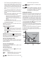
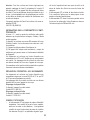
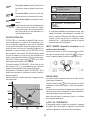
ECO REAL FEEL FUNCTION
ECO REAL FEEL is the innovative De’Longhi technology that works
simultaneously on temperature reduction and humidity control,
securing the best comfort level. With traditional systems, optimal
comfort conditions may be reached but not secured over time.
With ECO REAL FEEL, once optimal comfort is reached, compres-
sor operation and air flow are automatically modulated to keep
it consistent over time and save up to 30% on energy usage.
To activate the function, touch the
button (D9) on remote
control and the ECO REAL FEEL symbol appears.
The“ECO REAL FEEL”status indicator (C9) becomes white for approx-
imately 1 minute to indicate that the appliance is checking the room
conditions.
Afterwards the“ECO REAL FEEL”status indicator (C9) changes color
as it approaches comfort conditions (see following diagram).
For this type of use, the appliance must be set up in the air con-
ditioning mode.
HIGH
Operating curve
MEDIUM
LOW
Perfect!
TEMPERATURE
HIGH
MEDIUM
LOW
HUMIDITY

10
•
Touch the
timer button (D8): the timer symbol
(C15) and hours (C16) light up.
•
In particularly severe environmental conditions (large size
room, high temperature or humidity outside, poor insula-
tion of the room, too many of people or strong heat load
in the room, strong exposure to the sun ...) this device may
not be able to reach the best comfort level.
ARCTIC WHISPER EXTREME (available in air condition-
ing mode only)
By activating this function, the operating noise is further
reduced. To activate, touch the
button (D6) on the remote
control. The display shows the related symbol (C12).
SWING FUNCTION
This function moves the flap, evenly distributing the air into the
room.
When the
Swing button (D5) is touched, the flap will begin
to move forwards and backwards alternatively.
If touched again, the flap will be locked into its current position.
When the button is next touched, the flap will start to move for-
wards and backwards again.
Please note:
in order to avoid damaging the internal mecha-
nisms, the flap must not be moved manually.
SETTING THE TIMER
The timer allows the delayed start up or shut down of the appli-
ance. This function will prevent wasting electricity by optimizing
the operating periods.
How to program delayed shut down
•
While the appliance is ON in any operating mode, delayed
shut down can be programmed.
•
Touch the
(D3) and
(D4) buttons until the desired
number of hours to shut down appears on the display.
A few seconds after the timer is set, the setting is acquired, the
display shows the operating mode and the timer symbol stays lit.
Once the set time is elapsed, the air conditioner goes into Standby.
To cancel the timer program, touch the
timer button (D8)
twice. The timer symbol (C15) will go off.
Please note:
Once the timer has been activated, by touching the
timer button only one time, the remaining hours to shut down
will be displayed.
How to program delayed start up
•
Plug in the appliance and set to standby.
•
Touch the
timer button (D8): the timer symbol
(C15)
and hours (C16) light up.
•
Touch the
(D3) and
(D4) buttons until the desired
number of hours to start up appears. Start up can be pro-
grammed at any time within the 24 hours that follow.
When the set time is elapsed, the appliance will start to operate
in the same operating mode that was previously set.
To cancel the timer program, touch the timer button (D8) twice.
The timer symbol (C15) will go off.
Please note:
Once the timer has been activated, by touching the
timer key only one time, the remaining hours to the start up will
be displayed.
REPEAT PAIRING OF CST REMOTE CONTROL
The CST remote control is already pair to this DeLonghi Pinguino
appliance. In case you want to pair with another DeLongi Pin-
guino device, or in case of a pairing of brand new CST remote
control, the user needs to put the unit in Standby mode and
touch for 10 seconds the MODE selection button (D2) on the CST
remote control. The LED (D10) starts blinking periodically indi-
cating the pairing phase.
Then, press for 10 seconds the MODE button (C2) on the Pinguino
unit until a double beep is emitted. The pairing phase is signaled
on display by means of a fast flashing of the dot in the middle
of the digits.
When the two devices complete the pairing dialogue, the PAC
emits a double ‘beep’. The display will return to as it normally
GREEN LIGHT
: Most people feel good
room conditions, near optimal level.
BLUE LIGHT:
Best comfort level.
Perfect!
ORANGE LIGHT
: Room conditions far
from optimal level.

11
appears in the Standby mode.
NOTE:
pairing must be done within 60 seconds.
FCC AND CANADA EMC COMPLIANCE INFORMATION
This device complies with Part 15 of the FCC Rules. Operation is
subject to the following two conditions:
(1) This device may not cause harmful interference, and
(2) This device must accept any interference received, including
interference that may cause undesired operation.
Please note:
This equipment has been tested and found to com-
ply with the limits for a Class B digital device, pursuant to part 15
of the FCC Rules. These limits are designed to provide reasonable
protection against harmful interference in a residential instal-
lation. This equipment generates, uses and can radiate radio
frequency energy and, if not installed and used in accordance
with the instructions, may cause harmful interference to radio
communications. However, there is no guarantee that interfer-
ence will not occur in a particular installation. If this equipment
does cause harmful interference to radio or television reception,
which can be determined by turning the equipment off and ON,
the user is encouraged to try to correct the interference by one
or more of the following measures:
•
Reorient or relocate the receiving antenna.
•
Increase the separation between the equipment and re-
ceiver.
•
Connect the equipment into an outlet on a circuit different
from that to which the receiver is connected.
•
Consult the dealer or an experienced radio/TV technician
for help.
Approved under the certification provision of FCC Part 15 as a
Class B Digital Device.
Caution: Changes or modifications not expressly approved by
the manufacturer could void the user’s authority to operate this
device.
Caution:
To comply with the limits of the Class B digital device,
pursuant to Part 15 of the FCC Rules, this device is to comply with
Class B limits. All peripherals must be shielded and grounded.
Operation with non-certified peripherals or non shielded cables
my result in interference to radio or reception.
This Class B digital apparatus complies with Canadian ICES-003.
CAN ICES-3 (B)/NMB-3(B)
WIRELESS TRANSMITTER COMPLIANCE INFORMA-
TION
The term “IC:” before the radio certification number only signi-
fies that Industry Canada technical specifications were met.
This device complies with Industry Canada’s licence-exempt
RSSs. Operation is subject to the following two conditions:
(1) This device may not cause interference; and
(2) This device must accept any interference, including interfer-
ence that may cause undesired operation of the device.
This equipment complies with FCC and IC radiation exposure
limits set forth for an uncontrolled environment. This equipment
should be installed and operated with minimum distance 20cm
between the appliance and your body. This transmitter must
not be co-located or operating in conjunction with any other
antenna or transmitter.
FCC/IC RADIATION EXPOSURE STATEMENT
This equipment complies with FCC/IC RSS-102 radiation expo-
sure limits set forth for an uncontrolled environment.
This equipment should be installed and operated with minimum
distance 20cm between the radiator & your body.
Host device Labeling
This device includes the following module.
Contains FCC ID: WAP-2011
Host device Labeling
This device includes the following module.
Contains IC: 7922A-2011
USAGE TIPS
•
The CST remote control has humidity/temperature sensors
on board. It is suggested not to completely cover it with
hands or clothes; it is as well suggested not to place in ob-
structed air flow zones. In addition to that it is preferable to
keep the device far from direct sunlight exposure or heat
sources in order to avoid inaccurate sensor readings.
•
The CST remote control is equipped with touch sensitive
buttons. Operate with clean hands and without dust or
liquids nearby.
•
The CST Remote control is expected to run for approx. 6
months with the same batteries. This assumption is based
on the use of 2300 mAh LR6 “AA” batteries.

12
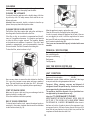
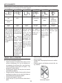
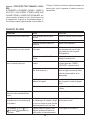
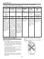
SELF-DIAGNOSIS
The appliance has a self diagnosis system to identify a number of warning/malfunctions.
Error messages are displayed on the appliance display.
IF ... IS SHOWN,
IF ... IS SHOWN,
IF ... IS SHOWN,
IF ... IS SHOWN,
IF ... IS SHOWN,
IF ... IS SHOWN,
“Low Temperature”
(Frost prevention)
“High Temperature”
“Low humidity”
“Probe Failure”
(Probe damaged)
“High Level”
(Internal tray full)
“Communication
Failure”
(Internal commu-
nication issue)
..WHAT SHOULD
I DO?
..WHAT SHOULD
I DO?
..WHAT SHOULD
I DO?
..WHAT SHOULD
I DO?
..WHAT SHOULD
I DO?
..WHAT SHOULD
I DO?
The appliance
is
The appliance is fitted
This message will
only be displayed
when in Eco Real
Feel function, in-
dicating that the
room humidity
level is extremely
low. To resume ope-
ration, switch the
unit to any other
mode other than
the Eco Real Feel
function.
If this is displayed,
Empty the internal
If this is displayed,
fitted with a frost
protection device to
avoid excessive for-
mation of ice. The
appliance starts up
again automatically
when the defrosting
process is completed.
with an overheating
device which in case
of operating condi-
tions with excessive
room
temperature
for a long period, will
switch the appliance
to ventilate only. The
call customer service
safety tank fol-
lowing the instruc-
tions in the section
“End of season
operations”
call customer ser-
vice
appliance will be au-
tomatically restored
as soon as the tem-
perature will be close
to the operating limit
conditions.
TIPS FOR CORRECT USE
To ensure optimal results from your air conditioner, follow these
recommendations:
•
Close the windows and doors where air conditioner will be
used. When installing the air conditioner semi-permanent-
ly, you should leave a door slightly open (as little as 0,39
inches - 1 cm) to guarantee proper ventilation.
•
Never use the appliance in very damp rooms (laundries for
example).
•
Protect the room from direct exposure to the sun by par-
tially closing curtains and/or blinds to make the appliance
much more economical to run.
•
Never use the appliance outdoors.
•
Make sure there are no heat sources in the room.
•
Make sure the air conditioner is standing on a level surface.
•
Never rest objects of any kind on the air conditioner.
•
Never obstruct the air intake or air outlet flap (see fig.
below).
do not cover the appliance

13
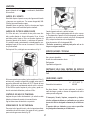
CLEANING
Before cleaning or maintenance, turn the appliance off by
touching the
button, then unplug from the outlet.
CLEANING THE APPLIANCE
You should clean the appliance with a slightly damp cloth then
dry with a dry cloth. For safety reasons, never wash the air con-
ditioner with water.
Attention!
Never use petrol, alcohol or solvents to clean the ap-
pliance. Never spray insecticide liquids or similar.
CLEANING THE BIO SILVER AIR FILTER
The BioSilver filter helps capture dust and pollen and helps re-
duce the growth of bacteria and mold on the filter.
If the filter is dirty, air circulation is compromised and the effi-
ciency of the appliance decreases. It is therefore good practice
to clean the filter at regular intervals. The frequency depends
on the duration and conditions of operation. If the unit is used
constantly or systematically, you are recommended to clean the
filter once a week. The filter is housed in the intake grille.
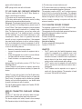
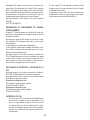
To clean the filter, extract as shown in fig. 9.
Use a vacuum cleaner to remove the dust collected on the filter.
If it is very dirty, immerse in warm water and rinse a number of
times. The water should never be hotter than 104°F. After wash-
ing the filter, allow it to dry completely before repositioning it.
START OF SEASON CHECKS
Make sure the power cable and plug are undamaged and the
electrical outlet is in working order.
Follow the installation instructions precisely.
END OF SEASON OPERATIONS
To drain all water from the circuit, remove the external cap by un-
screwing it in the counter clockwise direction and allow the water
to drain out into a basin (fig. 10).
When the appliance is empty, replace the caps.
Clean the filter and dry thoroughly before putting back.
In order to properly storage the appliance at the end of the sea-
son, we suggest you cover it with the supplied end of season
dust cover (B9) and you put the accessories in the relevant
end of season accessories bag (B8).
*dust cover and accessories bag only included with some
models.
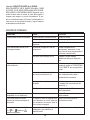
TECHNICAL
SPECIFICATIONS
Power supply voltage see rating label
Max. absorbed power
during air conditioning
“
Refrigerant “
Cooling capacity
“
ONLY FOR SERVICE CENTERS USE
THE WIRING DIAGRAM IS LOCATED INSIDE THE UNIT.
LIMIT
CONDITIONS
Room temperature for air conditioning 61° ÷ 95°F (16-35 °C)
Maximum relative humidity
80% RH
Please note:
outside of these conditions, the unit will take longer
or may not reach the cooling temperature that is set.
Transport, filling, cleaning, recovery and disposal of
refrigerant should be performed by a technical service
center appointed by the manufacturer only.
The appliance should be disposed of by a specialized cen-
ter appointed by the manufacturer only.
Attention!
TO AVOID DAMAGE TO THE UNIT:
NEVER TRANSPORT OR TURN THE APPLIANCE
UPSIDE
DOWN
OR
ON ITS SIDE. IF THIS OCCURS, WAIT 6 HOURS BEFORE TURNING
THE APPLIANCE ON, 24 HOURS IS RECOMMENDED. After the unit
has been on its side, oil needs to return to the compressor to en-
sure proper function. Without allowing the unit this time (6-24
hours) the unit may function for only a short time, and then the
compressor will break down from lack of oil.
10
9

14
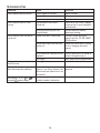
TROUBLESHOOTING
PROBLEM
CAUSE
SOLUTION
The air conditioner does not come ON
it is not plugged into the outlet
plug into the outlet
there is no power
wait for the current to return
the internal safety device has tripped
call the Service Center
The air conditioner works for a short
time only
there are bends or kinks in the air
exhaust hose
position the air hose correctly, keeping it
as short and free of curves as possible to
avoid bottlenecks
something is preventing the air from
being discharged
check and remove any obstacles
obstructing air discharge
The air conditioner works, but does not
cool the room
windows, doors and/or curtains open
close doors, windows and curtains,
bearing in mind the “TIPS FOR CORRECT
USE” given above
there are heat sources in the room (oven,
hairdryer, etc
minimize heat sources impact by setting
on low or unplugging unnecessary
sources
the air exhaust hose is detached from the
appliance
fit the air exhaust hose in the housing at
the back of the appliance (fig. 6).
filter clogged
clean or replace the filter as described above
During operation, there is an unpleasant
smell in the room
filter clogged or dirty
clean the filter as described above
The air conditioner does not operate for
about three minutes after restarting it
an internal safety device prevents the
appliance from being restarted until
three minutes have elapsed since it was
last turned off
wait. This delay is part of normal
operation.
The scripts
L
t
/H
t
/L
h
/P /HL/
and
the symbol appear on display.
the appliance has a self diagnosis system
to identify a number of malfunctions.
see the SELF-DIAGNOSIS chapter

15
Précautions importantes
•
Utilisez cet appareil uniquement tel que décrit dans le
présent manuel d’instructions. Comme avec tous les
appareils électriques, les instructions visent à couvrir
autant de situations que possible. Il faut utiliser des
précautions et du bon sens lorsque vous installez et
faites fonctionner ce conditionneur d’air.
•
Cet appareil a été fabriqué pour refroidir et
déshumidifier les environnements domestiques et il
ne doit pas être utilisé dans d’autres buts.
•
Il est dangereux d’altérer ou de modifier les
caractéristiques de l’unité de toutes façons.
•
L’appareil doit être installé conformément à la
législation nationale.
•
En cas de réparations, contactez le Centre de service
de réparations le plus proche. Il peut être dangereux
de réparer l’appareil sans autorisation.
•
L’appareil n’est pas prévu pour des personnes (y
compris des enfants) dont les capacités physiques,
sensorielles ou mentales sont diminuées, ou
manquent d’expérience et de connaissances, sauf
s’ils reçoivent de la supervision ou des instructions
sur l’utilisation de l’appareil par une personne
responsable de leur sécurité.
Les enfants doivent être supervisés pour s'assurer
qu'ils ne jouent pas avec l’appareil.
•
Si le câble d'alimentation est endommagé, il doit être
remplacé par le fabriquant ou un centre de maintenance
technique autorisé afin d’éviter tout risque.
•
Vérifiez toujours que l’appareil est branché dans
une prise à 3 fiches reliée à la terre. Si vous avez des
doutes, vérifiez avec un électricien qualifié.
•
N’utilisez pas de rallonge.
•
Avant toute opération de nettoyage ou de
maintenance, débranchez toujours l’appareil de la
prise.
•
Ne tirez pas sur le cordon d’alimentation ni n’appliquez
de contraintes lorsque vous déplacez l’appareil.
•
L'appareil ne doit pas être installé là où l’atmosphère
peut contenir des gaz combustibles, de l’huile ou du
soufre, ou près d’une source de chaleur.
•
Ne posez pas d’objets chauds ou lourds sur l’appareil.
•
Nettoyez les filtres au moins une fois par semaine.
•
Évitez d’utiliser des chauffages près de l’appareil.
•
L’appareil doit être transporté en position verticale.
S’il n’est pas possible de placer l’appareil dans un
angle, ne le couchez pas horizontalement.
•
Avant de transporter l’appareil, purgez-le. Après
le transport, attendez au moins 6 heures avant
d'allumer l’appareil.
•
Les matériaux d’emballage sont recyclables. Vous
devriez par conséquent les placer dans des conteneurs
spéciaux pour le tri sélectif des déchets.
•
Cet appareil est équipé d’un dispositif de sécurité.
Lorsque le compresseur est éteint, ce dispositif
l’empêche de s'allumer pendant 3 minutes.
•
AVERTISSEMENT: Les modifications non expressément
approuvées par l’entité responsable de la conformité
peuvent annuler l’autorisation de l’utilisateur
d’utiliser l’équipement.
Avertissements spécifiques concernant les appareils
contenant du gaz réfrigérant R410A
Le R410A est un réfrigérant qui respecte les normes
écologiques européennes ; néanmoins, il est recommandé
de ne pas percer le circuit de refroidissement de la machine.
A la fin de sa vie utile, remettez l’appareil à un centre de
collecte des déchets spéciaux pour son élimination. Ce
système hermétiquement scellé contient des gaz à effet
de serre fluorés.
INFORMATIONS ENVIRONNEMENTALES :
Cet appareil contient des gaz à effet de serre fluorés
couverts par le protocole de Kyoto.
La maintenance et l’élimination doivent être effectuées
uniquement par du personnel qualifié (R410A,
GWP=2088).
Conservez ces instructions
Ce produit est destiné au foyer
uniquement

16
INTRODUCTION
Merci d’avoir choisi un produit De’Longhi. Veuillez prendre un
instant pour lire les instructions afin d’éviter les risques ou d’en-
dommager l’appareil.
DESCRIPTION
Description de l’appareil (voir page 3 - A)
A1
volet de sortie d’air
A2
tableau de commande
A3
poignées
A4
roulettes
A5
filtre BioSilver
A6
grille d’entrée d’air
A7
logement du flexible d’évacuation d’air
A8
grille d’entrée d’air
A9
câble d’alimentation
A10
flexible de purge avec bouchon
A11
logement de la télécommande CST
Description des accessoires (voir page 3 - B)
B1
adaptateur pour support de fenêtre
B2
flexible d’évacuation d’air
B3
adaptateur pour flexible
B4
support de fenêtre supplémentaire
B5
support de fenêtre avec écrou à oreilles
B6
cache de support de fenêtre
B7
télécommande CST (Cool Surround Technology)
B8
sac d’accessoires de fin de saison (*pas disponible sur tous
les modèles)
B9
pare-poussière de fin de saison (*pas disponible sur tous
les modèles)
B10
bande mousse adhésive
RACCORD ÉLECTRIQUE
Avant de brancher l'appareil dans la prise, vérifiez les points
suivants :
•
L’alimentation électrique de la prise secteur correspond à la
valeur
indiquée sur la plaque signalétique à l’arrière de l’appareil.
•
La prise et le réseau électrique conviennent à
l'appareil.
•
La prise est une prise à 3 fiches reliée à la terre
. Si
ce n’est pas le cas, vous devez choisir une autre prise. Le
non-respect de ces instructions de sécurité importantes
dégage le fabricant de toute responsabilité.
Si cela devient nécessaire, le câble d’alimentation doit
être remplacé uniquement par un professionnel qualifié.
UTILISATION
Les instructions ci-dessous vous permettront de préparer votre
conditionneur d’air aussi efficacement que possible avant sa
mise en service. Avant d’utiliser l’appareil, assurez-vous que la
prise d’air et le volet de sortie d’air ne sont pas obstrués.
Remarque :
L’appareil est fourni avec une fonction d’auto-éva-
poration permettant d'éliminer le condensat pendant les modes
de refroidissement et de déshumidification.
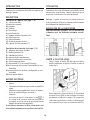
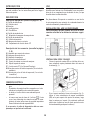
INSTALLATION DE LA CLIMATISATION
Pour des résultats optimaux, voir les illustrations
ci-dessous pour les distances minimales conseil-
lées.
FENÊTRE À GUILLOTINE DOUBLE
•
Placez le support de fenêtre (B5) dans l'appui de fenêtre,
étendez complètement le support à l'intérieur du cadre de
fenêtre (fig. 1).
•
Fixez le support avec l’écrou à oreilles (fig. 2). Fixez la bande
de mousse fournie (
B10
) en haut du support de fenêtre
puis abaissez la fenêtre sur le support. (Si le support de
fenêtre est trop grand pour la fenêtre, le plastique peut
être coupé avec une scie par un professionnel qualifié.)
1
20 in
50 cm
20 in
50 cm
20 in
50 cm
20 in
20 in
50 cm
50 cm
32 in
36 in
90 cm
80 cm

17
- Si les fenêtres sont grandes, utilisez un support de fenêtre
supplémentaire (B4) pour couvrir l'ouverture de votre fe-
nêtre, en l'étirant à la longueur requise, puis en le bloquant
avec l'écrou à oreilles fourni (fig. 3).
•
Montez le flexible d'évacuation d'air (B2) dans le logement
prévu à cet effet, situé à l’arrière de l'appareil (fig. 6).
•
Insérez et verrouillez l’accessoire pour support de fenêtre
(B1) déjà monté sur le flexible d’évacuation d’air, dans la
fente du support de fenêtre (fig. 4).
FENÊTRES
COULISSANTES
•
Grâce à l'écrou à oreilles, il est possible d'utiliser le support
de fenêtre également pour les fenêtres coulissantes. Posi-
tionnez le trou du support de façon à permettre une instal-
lation correcte du flexible d'échappement.
•
Pour faciliter le montage du flexible d’évacuation d’air (B2)
dans le logement prévu à cet effet situé à l’arrière de l’appa-
reil, positionnez les pattes de l’adaptateur de flexible (B3)
verticalement comme indiqué dans la fig. 5.
3
5
2
4
6

18
MANIPULATION À L’AIDE DU PANNEAU DE
COMMANDE
C17 C16 C15
C14
C6
C7
C8
C13
C1
Appuyez sur la touche
(C1) pour mettre l’appareil en
marche.
C3
Le volet A1 s’ouvre au bout de quelques secondes. Lorsque l’ap-
pareil s'allume, la dernière fonction activée avant l’extinction se
réactive.
C9
C10
C11
C12
C4
C2
C5
Remarque :
Si le démarrage n’est pas continu, après quelques
minutes la lumière d’affichage diminue pour réduire la consom-
mation d’énergie.
Pour éteindre l’appareil, appuyez sur la touche
puis débran-
chez la prise.
Remarque :
N’éteignez jamais le conditionneur d'air en dé-
branchant simplement la fiche de la prise. Appuyez sur la
touche
afin de placer votre conditionneur d’air en veille et
DESCRIPTION DU PANNEAU DE COMMANDE (C)
C1.
Touche ON/STAND-BY (marche/arrêt)
C2.
Touche de sélection de fonction MODE (climatisation,
déshumidification, ventilateur)
C3.
Touche augmentation
C4.
Touche diminution
C5.
Touche de sélection de la vitesse du ventilateur (MIN/MOY/
MAX/AUTO)
C6.
Symbole de climatisation
C7.
Symbole de déshumidification
C8.
Symbole de ventilation
C9.
Symbole/indicateur d’état ECO REAL FEEL
C10.
Symbole Swing
C11.
Indicateur de vitesse du ventilateur
C12.
Symbole ARCTIC WHISPER EXTREME
C13.
Symbole Alarme
C14.
Valeurs de température configurées, temps de marche/
arrêt programmé
C15.
Symbole minuterie
C16.
Indicateur minuterie
C17.
Indicateur d’échelle de température sélectionnée
MANIPULATION À PARTIR DU PANNEAU DE COM-
MANDE
ALLUMAGE ET ARRÊT DE L’APPAREIL
Insérez le bouchon dans la prise. Deux tirets apparaissent sur
l’écran indiquant que l’appareil est en mode veille.
attendez quelques minutes avant de débrancher la prise. De
cette manière, l'appareil peut effectuer les vérification de l’état
fonctionnel.
SÉLECTION DE MODE
Pour sélectionner le mode de
fonctionnement souhaité, appuyer
plusieurs fois sur la touche MODE
(C2) jusqu'à ce que la fonction sou-
haitée soit sélectionnée.
MODE CONDITIONNEMENT
Ce mode de fonctionnement est
idéal par temps chaud et humide
lorsque la pièce a besoin d'être re-
froidie. Cette fonction aide égale-
ment à déshumidifier l'air.
Pour régler correctement ce mode :
•
Appuyez plusieurs fois sur la
touche
MODE
(C2) jusqu’à ce
que le symbole de condition-
nement s’affiche. L’écran va
afficher la température désirée.
•
Pour changer la température
qu’on souhaite atteindre, ap-
puyez sur la touche
(C3) ou
(C4).
•
Sélectionnez la vitesse souhaitée pour le ventilateur en ap-
puyant sur le touche
(C5).

19
Les vitesses disponibles sont :
Vitesse minimum
: quand on souhaite le fonc-
tionnement
le plus silencieux possible.
Vitesse moyenne
: quand le niveau de bruit doit
être bas ais avec un bon niveau de confort.
Vitesse maximum
: pour atteindre la tempéra-
ture souhaitée le plus rapidement possible.
Auto
:
L’appareil choisit automatiquement la
vitesse de ventilateur la plus adaptée en fonction
de la température choisie et des conditions envi-
ronnementales.
MODE DÉSHUMIDIFICATION
Ce mode est idéal pour réduire l'hu-
midité dans la pièce (au printemps et
à l'automne, dans les pièces humides,
périodes pluvieuses, etc.). Pour ce
type d'utilisation, l'appareil doit être
réglé en mode conditionnement d'air.
En d'autres termes, le flexible d’éva-
cuation (B2) doit être fixé sur l’appa-
reil pour permettre à l'humidité de se
décharger à l’extérieur. Pour régler correctement ce mode :
•
Appuyez plusieurs fois que la touche
MODE
(C2) jusqu’à ce
que le symbole de déshumidification s'affiche.
•
L’appareil choisira automatiquement le débit d’air le plus
adapté.
MODE VENTILATEUR
Lorsque vous utilisez ce mode, le
flexible d’évacuation d'air (B2) n’a
pas besoin d’être fixé à l’appareil.
Pour régler correctement ce mode :
•
Appuyez plusieurs fois sur la
touche MODE (C2) jusqu’à ce
que le symbole
de venti-
lateur s’affiche.
•
Choisissez le débit d’air souhaité en appuyant sur la touche
(C5).
Les débits d'air disponibles sont :
Débit d’air minimum :
quand on souhaite un
fonctionnement le plus silencieux possible.
Débit d'air moyen
: lorsque le niveau de bruit
doit être faible mais avec un bon niveau de
confort.
Débit d'air maximum
: pour des performances
maximales.
SÉLECTIONNEZ L’UNITÉ DE MESURE DE LA TEMPÉ-
RATURE
Il est possible d’afficher la tem-
pérature en °C ou en °F. Pour
changer l’unité de mesure de
la température, appuyez simul-
tanément sur les deux touches
d’augmentation (C3) et de
diminution
(C4) pendant environ 10 s.
MANIPULATION AVEC LA TÉLÉCOMMANDE CST
(Cool Surround Tecnology)
La télécommande CST est basée sur la communication Blue-
tooth® Low Energy avec le Pinguino.
METTRE EN PLACE OU REMPLACER LES PILES
•
Retirez le couvercle à l’arrière de la télécommande.
•
Mettez en place ou remplacez-les par de nouvelles piles
LR6 “AA” 1.5V, en les introduisant correctement (voir les
instructions présentes dans le logement des piles) (fig. 7).
•
Remettre le couvercle en place.
Si la télécommande est remplacée ou mise au rebut, les piles
doivent être retirées et éliminées conformément à la législation
actuelle car elles sont nocives pour l’environnement.
Ne mélangez pas les anciennes et les nouvelles piles.
Ne mélangez pas des piles alcalines, standard (carbone-zinc)
ou rechargeable (nickel-cadmium). Ne jetez pas les piles dans
le feu. Les piles peuvent exploser ou fuir. Si vous n’utilisez plus
la télécommande pendant un certain temps, retirez les piles.
N'utilisez que des piles dont la date de péremption n’est pas
dépassée.
7
La page est en cours de chargement...
La page est en cours de chargement...
La page est en cours de chargement...
La page est en cours de chargement...
La page est en cours de chargement...
La page est en cours de chargement...
La page est en cours de chargement...
La page est en cours de chargement...
La page est en cours de chargement...
La page est en cours de chargement...
La page est en cours de chargement...
La page est en cours de chargement...
La page est en cours de chargement...
La page est en cours de chargement...
La page est en cours de chargement...
La page est en cours de chargement...
La page est en cours de chargement...
La page est en cours de chargement...
La page est en cours de chargement...
-
 1
1
-
 2
2
-
 3
3
-
 4
4
-
 5
5
-
 6
6
-
 7
7
-
 8
8
-
 9
9
-
 10
10
-
 11
11
-
 12
12
-
 13
13
-
 14
14
-
 15
15
-
 16
16
-
 17
17
-
 18
18
-
 19
19
-
 20
20
-
 21
21
-
 22
22
-
 23
23
-
 24
24
-
 25
25
-
 26
26
-
 27
27
-
 28
28
-
 29
29
-
 30
30
-
 31
31
-
 32
32
-
 33
33
-
 34
34
-
 35
35
-
 36
36
-
 37
37
-
 38
38
-
 39
39


DE LONGHI EX CST Series Le manuel du propriétaire
- Taper
- Le manuel du propriétaire
dans d''autres langues
Documents connexes
Autres documents
-
DeLonghi EL Series Manuel utilisateur
-
DeLonghi PINGUINO S1000 Manuel utilisateur
-
Danby DPAC120061 Manuel utilisateur
-
Honeywell HF0CESWK6 Le manuel du propriétaire
-
Honeywell HL12CESWW Manuel utilisateur
-
Danby APAC9036 Manuel utilisateur
-
-
Honeywell MO10CESWB Manuel utilisateur
-