Cobra 19 MINI CB Radio Transceiver Le manuel du propriétaire
- Taper
- Le manuel du propriétaire

A1 English
Our Thanks, The CB Story,
and Customer Assistance
Intro Operation Customer
Assistance
Warranty
Notice
Secondary Icons
Caution Warning
Installation Customer
Assistance
Introduction
Thank you for purchasing the Cobra 19 MINI CB Radio Transceiver.
Properly used, this Cobra product will give you many years of
reliable service.
The Citizens Band Story
The Citizens Band lies between the shortwave broadcast and 10-meter amateur radio bands,
and was established by law in 1949. The Class D two-way communications service
was opened in 1959. (CB also includes a Class A citizens band and Class C remote control
frequencies.)
Customer Assistance
Should you encounter any problems with this product, not understand its features, menu
or installation, please refer to the this owner's manual. If you require further assistance,
after reading this manual, we are here to help:
Have questions? Contact Cobra Electronics at
https://www.cobra.com/pages/contact-us or 800-543-1608
M-F 9:00AM - 5PM EST
For Assistance Outside the U.S.A.
Contact Your Local Dealer
Intro Operation Customer
Assistance
Warranty
Notice
Main Icons
Secondary Icons
Caution Warning
Installation Customer
Assistance
Customer Assistance
Nothing Comes Close to a Cobra®
®
Nothing Comes Close to a Cobra English
For more information or to
order any of our products,
please visit our website:
www.cobra.com
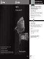
Owner’s Manual
19 MINI
CB Radio Transceiver
For more information or to order any of our products, please visit our website: www.cobra.com
English
© 2021 Cobra Electronics Corporation www.cobra.com
Cobra®, and the snake design are registered trademarks of Cobra Electronics Corporation, USA.
Cobra Electronics Corporation™ is a trademark of Cobra Electronics Corporation, USA.

Intro Operation Customer
Assistance
Warranty
Notice
Main Icons
Secondary Icons
Caution Warning
Installation Customer
Assistance
Introduction
A3
Product Features and
FCC Regulations
A2 English
Product Features
Intro Operation Customer
Assistance
Warranty
Notice
Main Icons
Secondary Icons
Caution Warning
Installation Customer
Assistance
Introduction
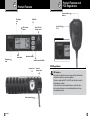
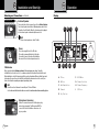
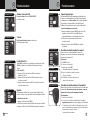
CH9/CH19
Power On-Off &
Volume Control
Squelch Control/SQ/ASQ
Antenna Jack
Microphone
Jack
TX Indicator
Icon
S/RF
Power Meter
LCD Channel
Display
External
Speaker Jack
Power Connection
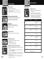
FCC Regulations •
FCC Compliance
Any changes or modifications not expressly approved by Cobra Electronics
could void your authority to operate the equipment.
This device complies with Part 15 of the FCC rules. Operation is subject to
the following two conditions:
(1) This device may not cause harmful interference, and (2) this device
must accept any interference received, including interference that may
cause undesired operation.
Intro Operation Customer
Assistance
Warranty
Notice
Main Icons
Secondary Icons
Caution Warning
Installation Customer
Assistance
Microphone Connector Detail
Menu/Lock Button
Channel Up/Down
Buttons
Push-To-Talk
(PTT)

Intro Operation Customer
Assistance
Warranty
Notice
Secondary Icons
Caution Warning
Installation Customer
Assistance
Introduction
1
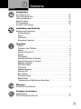
Contents
Introduction
Our Thanks to You .......................................... A1
The Citizens Band Story ...................................... A1
Customer Assistance ........................................ A1
Product Features. . . . . . . . . . . . . . . . . . . . . . . . . . . . . . . . . . . . . . . . . . . . A2
FCC Regulations ............................................ A3
Included in this Package ....................................... 2
Installation and Start-Up
Mounting and Connections ..................................... 3
Operation
CB Antenna ............................................. . 4
External Speaker .......................................... 4
Power .................................................. 4
Turning on Your CB Radio ................................ ... 6
Volume ................................................. 6
Channel 9/Channel 19 ...................................... 6
Squelch ................................................. 6
Auto Squelch ........................................ ..... 7
Operating Procedure to Receive .......................... .....
Operating Procedure to Transmit .............................. 7
Selecting a Channel ........................................... 8
S/RF Power Meter
..................................... .....
8
TX Indicator ................................. ............. 8
Frequency Ranges .............................. . ......... 10
Specifications .......................................... 11
Warranty
Limited One-Year Warranty .................................... 14
Customer Assistance
Product Service ............................................ 15
FCC/IC/RF Exposure Statement ................................ 16
Microphone Connector ...................................... 4
Display .................................................. 5
7
Channel Frequency ............................... ......... 8
Menu Options .............................. ...... ......... 9
Troubleshooting & Maintainance Adjustment .................... 12
Selecting VOX ............................... ............. 8

Notice Caution Warning
2English
You should find all of the following items in this package:
Intro Operation Customer
Assistance
Warranty
Notice
Secondary Icons
Caution Warning
Installation Customer
Assistance
Introduction
3
Installation and Start-Up
Intro Operation Customer
Assistance
Warranty
Notice
Secondary Icons
Caution Warning
Installation Customer
Assistance
Installation
Included in this Package
Intro Operation Customer
Assistance
Warranty
Notice
Secondary Icons
Caution Warning
Installation Customer
Assistance
Introduction
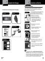
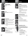
Select a location for the transceiver and microphone bracket that is convenient for
operation. In automobiles, the transceiver is usually mounted to the underneath of the
dash panel, with the microphone bracket beside it.
A universal mounting bracket is supplied along with self-tapping
screws and star washers. The transceiver is held in the
universal mounting bracket by two thumb screws, permitting
adjustment at the most convenient angle.
To mount and connect your transceiver:
1. Hold the radio with mounting bracket in the exact
location desired. Remove the mounting bracket
and use it as a template to mark the location for
the mounting screws.
2. Drill necessary holes and secure mounting
bracket in location.
3. Connect the antenna cable plug to the receptacle
marked “ANT” on the back of the unit.
4. Connect the red lead of the DC power cord
to an accessory 12 volt fuse.
5. Connect the black lead to the negative side
of the automobile. This is usually the chassis.
Any convenient location with good electrical
contact (remove paint) may be used.
6. Mount the microphone bracket in a convenient location
that does not interfere with vehicle operation using the
two screws supplied.
7. Connect the microphone RJ-45 plug to the 19 MINI RJ-45
front panel jack. Then install the radio into it's mounting
bracket securely.
Intro Operation Customer
Assistance
Warranty
Notice
Main Icons
Secondary Icons
Caution Warning
Installation Customer
Assistance
CB Tranceiver
Transceiver Bracket
Fuse Connection
Antenna Connector
Intro Operation Customer
Assistance Warranty
Notice
Main Icons
Secondary Icons
Caution Warning
Installation Customer
Assistance
Microphone Connector
Intro Operation Customer
Assistance Warranty
Notice
Main Icons
Secondary Icons
Caution
Warning
Installation Customer
Assistance
Operation
NOTE
For improved CB radio performance, connect the radio power leads directly to the
vehicle battery. This helps to ensure the following: 1) reduces conducted power line noise
into radio by taking advantage of the mechanical filtering properties of the vehicle battery.
2) Using the correct wire gauge between the battery and radio, helps to minimize Voltage
drop to the radio transmitter section to maximize transmitter RF output power.
CB Transceiver Microphone
Transceiver Bracket
Microphone Bracket
Operating Manual
Mounting and Connections •

Intro Operation Customer
Assistance
Warranty
Notice
Main Icons
Secondary Icons
Caution Warning
Installation Customer
Assistance
Operating Your CB Radio
5
4English
Operation
Installation and Start-Up
Intro Operation Customer
Assistance
Warranty
Notice
Main Icons
Secondary Icons
Caution Warning
Installation Customer
Assistance
Installation
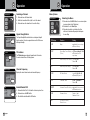
Microphone Connector
Allows for convenient removal of the Microphone plug
when storage is required. The Microphone MUST be
connected to the unit at all times, when in use, for
proper operation.
External Speaker
The speaker jack on the rear panel is used for an External Speaker.
The external speaker should have 8-Ohm impedance and be rated
to handle at least 4.0 watts. When the external speaker is plugged
in, the internal speaker is automatically disconnected.
NOTE
Cobra external speakers are rated 15 watts.
Microphone Connector
External Speaker Jack
Installation
Power Cable
Installation
NOTE
Cobra offers a line of antennas for use with your 19 Series CB Radio.
Go to cobra.com/collections/cb-radio-accessories for antenna and antenna mounting options.
CB Antenna
Only a properly matched Antenna system will allow maximum power output. In mobile
installations (cars, trucks, boats, etc.), an antenna system that is nondirectional should be used.
When installed in a boat, the transceiver will not operate at maximum efficiency without a ground
plate unless the vessel has a steel hull. Before installing the transceiver in a boat, consult your
dealer for information regarding an adequate grounding system.
Power
These wires supply Power to the CB radio.
This cable is permanently attached to the radio.
If you wish to remove the radio after installation,
disconnect at fuse holder and ground connector.
VOL
A. TX Icon
B. AM Icon
C. Auto Squelch Icon
D. Channel
E. Key Tone Icon
AB C D
E
F. S/RF Meter
G. Channel Lock Icon
H. Channel Frequency
I. VOX Icon
FGHI
Mounting and Connections continued •Display •

7
6English
y Icons
Installation
Main Icons
Operating Your CB Radio
OperationOperation
Intro Operation Customer
Assistance
Warranty
Notice
Secondary Icons
Caution Warning
Installation Customer
Assistance
Operating Your CB Radio
Channel 9/Channel 19 Button
To auto squelch your radio:
1. Push and hold the SQ/ASQ button until "AQ" shows on the LCD
display. The ASQ level set will also show in the lower left side
of the display.
2. Rotate the Channel knob to set the desired squelch level.
3. Push and release the SQ/ASQ button to save the setting.
Adjust Squelch
Turning on Your CB Radio
Push and release the Vol/ON/OFF knob to power
ON the radio.
On-Off/Volume Knob
Notice
Volume
Rotate the channel knob left or right to adjust the volume.
On-Off/Volume Knob
Notice
Channel 9/Channel 19
Set CH 9 to obtain instant access to the emergency channel.Set CH 19
to obtain instant access to the information and calling channel.
Channel 9/19 access:
1. Push and release the Channel 9/19 button to quick select channel 9.
2. Push and release the Channel 9/19 button a second time to
select channel 19.
3. Push and release the Channel 9/19 button a third time to return to the
last used channel
To squelch your radio:
1. Push and release the SQ/ASQ button.
2. Rotate the Channel knob to set the desired squelch level.
3. Push and release the SQ/ASQ button to save the setting.
Adjust Squelch
Auto Squelch
The Auto Squelch (ASQ) feature can help to improve the receiver
performance experience when enabled for communicating with
nearby stations. For weaker or more distant stations consider using
the SQ (traditional squelch) system or disable squelch for continuous
receiver audio.
Operating Procedure to Receive
Be sure the power cord, antenna and microphone are connected to
the proper connectors before proceeding further (see pages 4 and 5).
To receive:
1. Turn ON the radio.
2. Select the desired channel.
3. Set squelch to OFF (audio noise heard from speaker).
4. Set the receiver volume to a comfortable listen level.
5. Reset the squelch level for the intended listening requirements.
On-Off/Volume Knob
Squelch/ASQ Button
Press-to-Talk Switch
Main Icons
Squelch
This control is used to cut off or eliminate receiver background noise in the
absence of an incoming signal when properly adjusted.
Operating Procedure to Transmit
Be sure the antenna is properly connected to the radio before
transmitting. Prolonged transmitting without an antenna, or with a
poorly matched antenna, could cause damage to the transmitter.
To transmit:
1. Select the desired channel.
2. The receiver and transmitter are controlled by
the Push-to-Talk switch on the microphone.
Press the switch and the transmitter is activated; release
switch to receive. When transmitting
(on a clear channel), hold the microphone
two inches from the mouth and speak clearly
in a normal voice.

9
8English
Installation Customer
Assistance
Main Icons
Intro Operation Customer
Assistance
Warranty
Notice
Secondary Icons
Caution Warning
Installation Customer
Assistance
Operating Your CB Radio
Operation
Intro Operation Customer
Assistance
Warranty
Notice
Secondary Icons
Caution Warning
Installation Customer
Assistance
Operating Your CB Radio
Signal Strength Meter
The Signal Strength Meter indicates the received signal strength
from the antenna. The meter segments shown on the LCD increase
with signal strength.
TX Indicator
The TX Indicator appears when in transmit mode. In this mode,
the meter shows all bars at full output power.
Channel Frequency
Displays the current channel and receive transmit frequency.
Enable/Disable VOX
1. Push and hold the Push-To-Talk switch on the microphone, then
2. Push and release the MENU button.
3. This will both enable/disable the VOX function.
S/RF Power Meter
TX Indicator
Main Icons
Channel Frequency
Channel Selection
Intro Operation
1. Push and release the Channel knob.
2. Rotate the channel knob left or right to select the channel.
3. Push and release the channel knob to save the setting.
Selecting a Channel
LCD Display Function Setting
KEY BP Beep on (default): turn on beep
oF: turn off beep
ROG BP
Roger Beep Sound Setting
oF, Tone settings 01 - 06
(Tones) oF: (default) turn off
roger beep
VOX L
VOX Sensitivity Level Setting
Level: 01 - 09
Default: 03
VOX T VOX Delay Time Setting Level: 01 - 09
Default: 01
RF.GAIN RF Gain Control Levels
: 03, 06, 09 - 48
oF (default) RF gain off
TOTSET Time Out Timer oF, 01 - 10 minutes
Default: 05
PWRAUTO
Automatic Power On Setting
on
(default): Auto power on
oF:
Manual power on
FW VER
Firmware Version
Displays 2-digit
Firmware Version
RESET
See Reset to Factory
Default Section
Menu Options
1. Push and release the MENU button to access menu options
(see menu options in the Table below).
2. Rotate knob to select Menu Option
3. Push and release knob on selected option, then
rotate knob to desired setting and push knob again
to save setting
Selecting the Menu
Selecting the Menu
Intro Operation
Operation
VOX

Intro Operation Customer
Assistance
Warranty
Notice
Secondary Icons
Caution Warning
Installation Customer
Assistance
Operating Your CB Radio
11
10 English
Intro Operation Customer
Assistance
Warranty
Notice
Secondary Icons
Caution Warning
Installation Customer
Assistance
Operating Your CB Radio
Intro Operation Customer
Assistance
Warranty
Notice
Secondary Icons
Caution Warning
Installation Customer
Assistance
Operating Your CB Radio
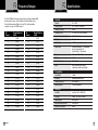
Specifications
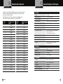
Frequency Ranges
CB
Channel
Channel Frequency
in MHz
1 26.965
2 26.975
3 26.985
4 27.005
5 27.015
6 27.025
7 27.035
8 27.055
9 27.065
10 27.075
11 27.085
12 27.105
13 27.115
14 27.125
15 27.135
16 27.155
17 27.165
18 27.175
19 27.185
20 27.205
CB
Channel
Channel Frequency
in MHz
21 27.215
22 27.225
23 27.255
24 27.235
25 27.245
26 27.265
27 27.275
28 27.285
29 27.295
30 27.305
31 27.315
32 27.325
33 27.335
34 27.345
35 27.355
36 27.365
37 27.375
38 27.385
39 27.395
40 27.405
The Cobra 19 MINI radio transceiver represents one of the most advanced AM
two-way radios for use as a Class D station in the Citizens Radio Service.
This unit features advanced Phase Lock Loop (PLL) circuitry providing
complete cov er age of all 40 CB chan nels.
Notice
y Icons
Caution
Notice
Secondary Icons
Caution
General
Channels CB – 40 CH
Frequency Range CB – 26.965 to 27.405 MHZ
Frequency Tolerance 0.005 %
Frequency Control PLL (Phase Lock Loop) Synthesizer
Operating Temperature Range -30° C TO + 65° C
Microphone Plug-in Condenser
Input Voltage 13.8VDC nom. (negative ground)
Current Drain Transmit: AM full mod., 1.4A (maximum)
Receive: Squelched, 0.9 A;
full audio output, 1.2A (nominal)
Size 1.75” H x 4.5” W x 7” D
Weight 3.25 lbs.
Antenna Connector UHF; SO-239
Meter LCD’s; indicates relative power
output and received signal strength
Transmitter
Power Output 4 watts
Modulation AM (Amplitude Modulation)
Frequency Response 300 to 3000 Hz
Output Impedance 50 ohms, unbalanced
Receiver
Sensitivity Less than 1 µV for 10dB (S+N)
Selectivity 6 dB @ 7 KHz, 60 dB @ 10KHz
Image Rejection 60 dB, typical
Adjacent-Channel Rejection 50 dB, typical
Automatic Noise Limiter Built-in

13
Maintainance/Adjustment
Troubleshooting
Troubleshooting &
Maintenance/Adjustment
Use of a CB receiver at low signal levels is normally limited by the presence of electrical noise.
Under most operating conditions, when signal level is adequate, the background noise does not
present a serious problem. Also, when extremely low level signals are being received, the transceiver
may be operated with vehicle engine turned off. The unit requires very little current and therefore
will not significantly discharge the vehicle battery.
Even though this radio has an automatic noise limiter, in some installations ignition interference
may be high enough to make good communications impossible. Consult your authorized Cobra
dealer or a two-way radio technician for help in locating and correcting the source of severe noise.
Troubleshooting &
Maintenance/Adjustment
•
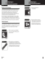
Your Cobra CB transceiver is specifically designed for the environment encountered in
mobile installations. The use of all solid state circuitry and its light weight result
in high reliability. Should a failure occur, however, review the following, then if necessary,
replace parts only with identical parts. Do not substitute.
Check Power Source
Check Fuses in DC Power Cord
1. Check connections to the source of power
and make sure it is the 13.8 VDC required
to operate your radio.
2. Check the fuses in the DC power cord.
The main power lead (red) has a two amp
3AG type fuse in its holder. Use only the
above specified type and size fuse for
maximum protection. Failure to do so
will void the warranty.
Maintenance/Adjustment
English
Main Icons
Check Microphone Connection
Check Antenna Connection
3. Make certain the microphone is properly
plugged in.
4. Make certain the antenna is properly
assembled and connected.
If you are unable to correct the problem,
refer to product service on page 14 for
the correct procedure for warranty and
post-warranty service from Cobra.
12 English
•
Ignition Noise Interference

Intro Operation Customer
Assistance
Warranty
Notice
Main Icons
Secondary Icons
Caution Warning
Installation Customer
Assistance
Intro Operation Customer
Assistance
Warranty
Notice
Main Icons
Secondary Icons
Caution Warning
Installation Customer
Assistance
NOTES
Main Icons
Product Service
Customer Assistance
15
14 English
If you have any questions about operation or installing your new Cobra product,
PLEASE CONTACT COBRA FIRST…do not return this product to any retail store.
The contact information for Cobra will vary depending on the country in which you purchased
and utilize the product. For the latest contact information, please go to www.cobra.com/support
For products purchased in the U.S.A. you may call 800-543-1608.
For products purchased in the U.S.A., if your product should require factory service, please
please go to www.cobra.com/support and follow the instructions for returning your product
to the Cobra Factory Service Department for service.
Should there be any problems with this product or further information is needed on its features
please visit www.cobra.com for support, frequently asked questions, Declarations of Conformity,
and full manuals.
For Products Purchased Outside the U.S.A. or Canada
Please contact your local dealer for product service information.
For Products Used in Canada
Industry Canada Notice
This device complies with Industry Canada license-exempt RSS standard(s). Operation is subject
to the following two conditions:
(1) this device may not cause interference, and
(2) this device must accept any interference, including interference that may cause
undesired operation of the device.
Le présent appareil est conforme aux CNR d’Industrie Canada applicables aux appareils radio
excempts de licence. L;exploitation est autorisée aux deux condtions suivantes:
(1) l’appariel ne doit pas produire de brouillage, et
(2) l’utilisateur de l’appareil doit accepter tout brouillage radioélectrique subi, même si le
brouillage est susceptible d’en compromettre le fonctionnement.
•
•
Warranty
Limited One-Year Warranty
Warranty Terms:
Cobra warrants your product against all defects in materials and workmanship for a period of one (1)
year from the date of original purchase.
Cobra, at our sole discretion, will repair or replace your product (with the same or comparable product)
free of charge.
Cobra will not pay shipping charges that you incur for sending your product to us. Products received
COD will be refused.
To make a warranty claim, we will require proof or purchase in the form of an invoice or receipt. No
proof of purchase is required for factory direct purchases.
Warranty Exclusions: Warranty does not apply to your product under any of the following conditions:
1. The serial number has been removed or modified. 2. Your product has been subjected to misuse or
damage (including water damage, physical abuse, and/or improper installation). 3. Your product has
been modified in any way. 4. Your receipt or proof-of-purchase is from a non-authorized dealer or
internet auction site including E-bay, U-bid, or other non-authorized resellers.
LIMITATION OF WARRANTY: EXCEPT AS EXPRESSLY PROVIDED HEREIN, YOU ARE ACQUIRING THE
PRODUCT "AS IS" AND "WHERE IS", WITHOUT REPRESENTATION OR WARRANTY. COBRA
SPECIFICALLY DISCLAIMS ANY REPRESENTATION OR WARRANTY INCLUDING, BUT NOT LIMITED
TO THOSE CONCERNING THE MERCHANTABILITY AND SUITABILITY OF THE PRODUCT FOR A
PARTICULAR PURPOSE. COBRA SHALL NOT BE LIABLE FOR CONSEQUENTIAL, SPECIAL OR
INCIDENTAL DAMAGES INCLUDING, WITHOUT LIMITATION, DAMAGES ARISING OUT OF THE USE,
MISUSE OR MOUNTING OF THE PRODUCT.
The above limitations or exclusions shall be limited to the extent they violate the laws of any particular
state. Cobra is not responsible for products lost in shipment between the owner and our service center.
General Warranty Information
Each product we manufacture is covered by our factory warranty. While each product may have unique
components and policy, the general guideline below will apply to most Cobra products.
All Cobra products purchased factory-direct or from our Authorized Resellers will come with a full one
to three (1-3) year warranty from the date of the original retail purchase (see policy statement above
for full warranty details and exclusions).
Standard accessories packaged with each model will have a one-year factory warranty.
Accessory items have a one-year factory warranty.
Shipping to our facility is not covered in our warranty. Return shipping is included within the US.
This warranty is non-transferrable.
For the sake of clarity, ‘repair or replace the Product or its defective part’ does not include removal or
installation work, costs or expenses which include but are not limited to labor costs or expenses.
Cobra will not be responsible for lost packages.

17
16 English
Intro Operation Customer
Assistance
Warranty
Notice
Secondary Icons
Caution Warning
Installation Customer
Assistance
Intro Operation Customer
Assistance
Warranty
Notice
Main Icons
Secondary Icons
Caution Warning
Installation Customer
Assistance
NOTES
Customer Assistance
FCC/IC/RF Exposure Statement
FCC Part 15.19 Warning Statement
THIS DEVICE COMPLIES WITH PART 15 OF THE FCC RULES. OPERATION IS SUBJECT TO THE
FOLLOWING TWO CONDITIONS: (1) THIS DEVICE MAY NOT CAUSE HARMFUL INTERFERENCE, AND
(2) THIS DEVICE MUST ACCEPT ANY INTERFERENCE RECEIVED, INCLUDING INTERFERENCE THAT
MAY CAUSE UNDESIRED OPERATION.
FCC Part 15.21 Warning Statement-
NOTE: THE GRANTEE IS NOT RESPONSIBLE FOR ANY CHANGES OR MODIFICATIONS NOT
EXPRESSLY APPROVED BY THE PARTY RESPONSIBLE FOR COMPLIANCE. SUCH MODIFICATIONS
COULD VOID THE USER’S AUTHORITY TO OPERATE THE EQUIPMENT.
FCC Part 15.105(b) Warning Statement
NOTE: This equipment has been tested and found to comply with the limits for a Class B digital
device, pursuant to part 15 of the FCC Rules. These limits are designed to provide reasonable
protection against harmful interference in a residential installation. This equipment generates
uses and can radiate radio frequency energy and, if not installed and used in accordance with
the instructions, may cause harmful interference to radio communications. However, there is no
guarantee that interference will not occur in a particular installation. If this equipment does cause
harmful interference to radio or television reception, which can be determined by turning the
equipment off and on, the user is encouraged to try to correct the interference by one or more of the
following measures:
- Reorient or relocate the receiving antenna.
- Increase the separation between the equipment and receiver.
- Connect the equipment into an outlet on a circuit different from that to which the receiver
is connected.
- Consult the dealer or an experienced radio/TV technician for help.
IC RSS-GEN, Sec 8.3 Warning Statement
ENGLISH: This radio transmitter (identify the device by certification number, or model number
if Category II) has been approved by Industry Canada to operate with the antenna types listed
below with the maximum permissible gain and required antenna impedance for each antenna
type indicated. Antenna types not included in this list, having a gain greater than the maximum
gain indicated for that type, are strictly prohibited for use with this device.
Immediately following the above notice, the manufacturer shall provide a list of all antenna types
approved for use with the transmitter, indicating the maximum permissible antenna gain (in dBi)
and required impedance for each.
FRENCH: Le présent émetteur radio (identifier le dispositif par son numéro de certification ou son
numéro de modèle s’il fait partie du matériel de catégorie I) a été approuvé par Industrie Canada
pour fonctionner avec les types d’antenne énumérés ci-dessous et ayant un gain admissible
maximal et l’impédance requise pour chaque type d’antenne. Les types d’antenne non inclus
dans cette liste, ou dont le gain est supérieur au gain maximal indiqué, sont strictement interdits
pour l’exploitation de l’émetteur.
RF Exposure Statement
ENGLISH: This equipment complies with FCC radiation exposure limits set forth for an
uncontrolled environment. This equipment should be installed and operated with minimum
distance 40cm between the radiator & your body.
The device is in compliance with RF exposure guidelines, users can obtain Canadian information
on RF exposure and compliance. The minimum distance from body to use the device is 40cm.
FRENCH: Le présent appareil est conforme
Après examen de ce matériel aux conformité ou aux limites d’intensité de champ RF, les
utilisateurs peuvent sur l’exposition aux radiofréquences et compliance d’acquérir les
informationscorrespondantes. La distance minimale du corps à utiliser le dispositif est de 40cm.
IC RSS-GEN, Sec 8.4 Warning Statement
ENGLISH: This device complies with Industry Canada license-exempt RSS standard(s). Operation
is subject to the following two conditions: (1) this device may not cause interference, and (2) this
device must accept any interference, including interference that may cause undesired operation
of the device.
FRENCH: Le présent appareil est conforme aux CNR d’Industrie Canada applicables aux appareils
radio exempts de licence. L’exploitation est autorisée aux deux conditions suivantes : (1) l’appareil
ne doit pas produire de brouillage, et (2) l’utilisateur de l’appareil doit accepter tout brouillage
radioélectrique subi, même si le brouillage est susceptible d’en compromettre le fonctionnement.

A1 Français
Nos remerciements, l’histoire
du CB et assistance à la clientèle
Intro Operation Customer
Assistance
Warranty
Notice
Secondary Icons
Caution Warning
Installation Customer
Assistance
Introduction
Merci d’avoir acheté le mini récepteur radio CB Cobra 19.
Utilisé adéquatement, ce produit Cobra vous donnera de
nombreuses années de service fiable.
L’histoire de Citizens Band
La bande des citoyens se situe entre les bandes de radioamateur en ondes courtes et les
bandes de radioamateur de 10 mètres, et a été créée par la loi en 1949. Le service de
communications bidirectionnelles de classe D a été ouvert en 1959.
(CB comprend également une bande de citoyens de classe A et des fréquences de
télécommande de classe C.)
Assistance à la clientèle
Si vous rencontrez des problèmes avec ce produit, ne comprenez pas ses fonctionnalités,
son menu ou son installation, veuillez vous référer au manuel du propriétaire.
Si vous avez besoin d’aide supplémentaire, après avoir lu ce manuel, nous sommes
là pour vous aider :
Vous avez des questions ? Veuillez contacter Cobra Electronics au
https://www.cobra.com/pages/contact-us ou 800-543-1608
Lu-Ve 9 h - 17 h PM EST
Pour de l’assistance en dehors des États-Unis
Communiquez avec votre revendeur local
Intro Operation Customer
Assistance
Warranty
Notice
Main Icons
Secondary Icons
Caution Warning
Installation Customer
Assistance
Assistance à la clientèle
Nothing ComesClose to a Cobra®
®
NothingComes Close to a Cobra English
For more information or to
order any of our products,
please visit our website:
www.cobra.com
Eng
g
Eng
l
i
s
o
b
r
to
Cl
o
C
ome
thi
s
h
a
a®
a
a
o
s
ome
n
g
N
Eng
b
Cl
C
thi
N
o
thi
n
g
C
ome
s
Cl
o
s
e
to
a
C
o
b
a
Eng
l
i
s
h
N
o
thi
n
g
C
ome
s
Cl
o
s
e
to
a
C
o
b
r
a
Eng
l
i
s
h
o
b
to
C
Comes
t
h
C
e
Comes
g
o
b
to
C
l
Comes
h
in
www.cobra.com
www.cobra.com
www.cobra.com
www.cobra.com
www.cobra.com
www.cobra.com
website:
website:
our
www.cobra.com
visit
www.cobra.com
please
www.cobra.com
website:
website:
visit
our
please
visit
please
products,
products,
website:
our
our
any
visit
order
please
products,
products,
of
any
order
to
products,
information
products,
information
our
more
any
For
more
order
or
information
information
more
For
to
information
information
information
more
o
Comes
Comes
o
t
r
a
a
l
o
Comes
in
C
o
b
to
Comes
C
Comes
o
t
h
www.cobra.com
www.cobra.com
www.cobra.com
www.cobra.com
www.cobra.com
www.cobra.com
www.cobra.com
website:
website:
our
www.cobra.com
visit
www.cobra.com
please
www.cobra.com
website:
website:
visit
please
products,
website:
products,
website:
our
our
any
visit
order
please
products,
products,
our
of
order
products,
information
products,
information
our
more
any
For
order
to
information
information
information
more
or
to
information
information
more
For
more
o
t
h
in
g
Comes
C
l
o
e
to
a
C
o
b
r
a
For
more
information
or
to
order
any
of
our
products,
please
visit
our
website:
www.cobra.com
Manuel du propriétaire
19 MINI
Récepteur radio CB
Pour de plus amples renseignements ou pour commander l’un de nos produits,
veuillez visiter notre site Web : www.cobra.com
Français
©2021 Cobra® Electronics Corporation www.cobra.com
Cobra® et le dessin du serpent sont des marques déposées de Cobra Electronics Corporation, É.-U.
Cobra Electronics CorporationMC est une marque de commerce de Cobra Electronics Corporation, É.-U.

Intro Operation Customer
Assistance
Warranty
Notice
Main Icons
Secondary Icons
Caution Warning
Installation Customer
Assistance
Introduction
A3
Caractéristiques du produit
et réglementations
A2 Français
Caractéristiques du produit
Intro Operation Customer
Assistance
Warranty
Notice
Main Icons
Secondary Icons
Caution Warning
Installation Customer
Assistance
Introduction
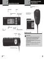
CH9/CH19
Mise sous tension-arrêt
et contrôle du volume
Commande Squelch/SQ/ASQ
Prise d’antenne
Prise
microphone
Icône d’indicateur
TX
Capteur de puissance
S/RF
Affichage des canaux
LCD
Connexion
d’alimentation
Prise de haut-parleur externe
Règlements de la FCC •
Conformité à la FCC
Tout changement ou modification non expressément approuvée par Cobra
Electronics pourrait annuler votre autorisation d’utiliser l’équipement.
Cet appareil est conforme à la section 15 du règlement de la FCC
(FEDERAL COMMUNICATIONS COMISSION). Le fonctionnement est soumis aux
deux conditions suivantes :
(1) Cet appareil ne peut causer d’interférences nuisibles, et (2) il doit accepter
toutes interférences reçues, notamment celles pouvant entraîner un
dysfonctionnement.
Intro Operation Customer
Assistance
Warranty
Notice
Main Icons
Secondary Icons
Caution Warning
Installation Customer
Assistance
Détails du connecteur de microphone
Bouton Menu/
Verrouillage
Boutons Haut/Bas
de canal
Push-To-Talk (PTT)
(Appuyer pour parler)

Intro Operation Customer
Assistance
Warranty
Notice
Secondary Icons
Caution Warning
Installation Customer
Assistance
Introduction
1
Contenu
Introduction
Nous vous remercions ....................................... A1
L’histoire de Citizens Band .................................... A1
Assistance à la clientèle ..................................... A1
Caractéristiques du produit. .. . . . . . . . . . . . . . . . . . . . . . . . . . . . . . . . . . . A2
Règlements de la FCC ....................................... A3
Inclus dans cet emballage ..................................... 2
IInstallation et démarrage
Montage et connexions ........................................ 3
Fonctionnement
Antenne CB ............................................. . 4
Haut-parleur externe ........................................ 4
Puissance ................................................ 4
Allumer votre radio CB ................................ ... 6
Volume ................................................. 6
Canal 9/Canal 19 ...................................... 6
Squelch ................................................. 6
Squelch automatique .................................. ..... 7
Procédure de fonctionnement à recevoir
.................... .....
Procédure de fonctionnement à transmettre ......................7
Choisir un canal .......................................... 8
Capteur de puissance S/RF.............................. ..... 8
Indicateur TX ................................ ............. 8
Gammes de fréquence ............................ . .........10
Caractéristiques techniques ................................. 11
Garantie
Garantie limitée d’un an .......................................14
Assistance à la clientèle
Service au produit ........................................... 15
Déclaration d’exposition FCC/IC/RF ..............................16
Connecteur de microphone ...................................4
Écran ................................................... 5
7
Fréquence de canal ............................... ......... 8
Options du menu ........................... ...... ......... 9
Dépannage et ajustement de maintenance ......................12
Choisir VOX ................................. ............. 8
Réinitialiser aux valeurs d'usine par défaut ...................... 8

Notice Caution Warning
2Français
Vous devriez trouver tous les éléments suivants dans cet emballage :
Intro Operation Customer
Assistance
Warranty
Notice
Secondary Icons
Caution Warning
Installation Customer
Assistance
Introduction
3
Installation et démarrage
Intro Operation Customer
Assistance
Warranty
Notice
Secondary Icons
Caution Warning
Installation Customer
Assistance
Installation
Inclus dans cet emballage
Intro Operation Customer
Assistance
Warranty
Notice
Secondary Icons
Caution Warning
Installation Customer
Assistance
Introduction
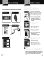
Sélectionnez un emplacement pour l’émetteur-récepteur et le support du microphone
qui convient au fonctionnement. Dans les automobiles, l’émetteur-récepteur est
généralement fixé sous le tableau de bord, avec le support de microphone à côté.
Un support de montage universel est fourni avec des vis
autotaraudeuses et des rondelles en étoile. L’émetteur-récepteur
est maintenu dans le support de montage universel par deux
vis à molette, permettant un réglage à l’angle le plus pratique.
Pour monter et connecter votre émetteur-récepteur :
1. Tenez la radio avec support de montage à l’emplacement
exact souhaité. Retirez le support de montage et
utilisez-le comme modèle pour marquer l’emplacement
des vis de montage.
2. Percez les trous nécessaires et fixez le support
de montage à l’emplacement.
3. Connectez la fiche du câble d’antenne à la prise
marquée « ANT » à l’arrière de l’unité.
4. Connectez le fil rouge du cordon d’alimentation
CC à un fusible accessoire de 12 volts.
5. Connectez le fil noir au côté négatif de l’automobile.
Il s’agit généralement du châssis.
Tout emplacement pratique avec un bon contact
électrique (enlever la peinture) peut être utilisé.
6. Montez le support du microphone dans un endroit
pratique qui n’interfère pas avec le fonctionnement
du véhicule à l’aide des deux vis fournies.
7. Connectez la prise microphone RJ-45 à la prise
19 Mini RJ-45 du panneau avant. Ensuite, installez
la radio dans son support de montage en toute sécurité.
Intro Operation Customer
Assistance
Warranty
Notice
Main Icons
Secondary Icons
Caution Warning
Installation Customer
Assistance
Émetteur-récepteur CB
Support de l’émetteur-récepteur
Connexion de fusible
Connecteur d’antenne
Intro Operation Customer
Assistance Warranty
Notice
Main Icons
Secondary Icons
Caution Warning
Installation Customer
Assistance
Connecteur de microphone
Intro Operation Customer
Assistance Warranty
Notice
Main Icons
Secondary Icons
Caution
Warning
Installation Customer
Assistance
Operation
REMARQUE
Pour améliorer le rendement de la radio CB, connectez l’alimentation radio directement à la
batterie du véhicule. Cela permet de s’assurer de ce qui suit : 1) réduire le bruit de la ligne
électrique conduite en radio en tirant parti des propriétés de filtrage mécanique de la batterie du
véhicule. 2) Utiliser la jauge de fil correcte entre la batterie et la radio, aider à minimiser la chute
de tension à la section de l’émetteur radio pour maximiser la puissance de sortie RF de
l’émetteur.
Émetteur-récepteur CB Microphone
Support de l’émetteur-récepteur
Support du microphone
Manuel d’utilisation
Montage et connexions •
boîtier de fusible
Rouge+
Noir-
châssis

Intro Operation Customer
Assistance
Warranty
Notice
Main Icons
Secondary Icons
Caution Warning
Installation Customer
Assistance
Utilisation de votre radio CB
5
4Français
Fonctionnement
Installation et démarrage
Intro Operation Customer
Assistance
Warranty
Notice
Main Icons
Secondary Icons
Caution Warning
Installation Customer
Assistance
Installation
Connecteur de microphone
Permet de retirer facilement la prise microphone
lorsque le stockage est nécessaire. Le microphone
DOIT être connecté à l’appareil en tout temps,
lorsqu’il est utilisé, pour un bon fonctionnement.
Haut-parleur externe
La prise du haut-parleur sur le panneau arrière est utilisée pour
un haut-parleur externe. Le haut-parleur externe doit avoir une
impédance de 8 Ohm et être évalué pour gérer au moins 4,0 watts.
Lorsque le haut-parleur externe est branché, le haut-parleur interne
est automatiquement déconnecté.
REMARQUE
Les haut-parleurs externes Cobra sont évalués à 15 watts.
Connecteur de microphone
Prise de haut-parleur externe
Installation
Câbles d’alimentationInstallation
REMARQUE
Cobra propose une gamme d’antennes à utiliser avec votre radio CB série 19.
Accédez à cobra.com/collections/cb-radio-accessories pour l’antenne et les
options de montage d’antenne.
Antenne CB
Seul un système d’antenne correctement adapté permettra une puissance de sortie maximale. Dans les
installations mobiles (voitures, camions, bateaux, etc.), un système d’antenne non directionnel doit être utilisé.
Lorsqu’il est installé dans un bateau, l’émetteur-récepteur ne fonctionnera pas à une efficacité maximale sans
plaque de sol à moins que le navire n’ait une coque en acier. Avant d’installer l’émetteur-récepteur dans un
bateau, consultez votre concessionnaire pour obtenir des renseignements sur un système de mise à la terre
adéquat.
Puissance
Ces fils alimentent la radio CB.
Ce câble est fixé en permanence à la radio.
Si vous souhaitez retirer la radio après l’installation,
débranchez-la au niveau du porte-fusible et du connecteur de masse.
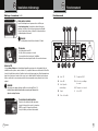
VOL
A. Icône TX
B. Icône AM
C. Icône Squelch
automatique
D. Canal
E. Cône clé tonalité
AB C D
E
F. Compteur S-RF
G. Icône de verrouillage
de canal
H. Fréquence de canal
I. Icône VOX
FGHI
Montage et connexions
(suite) •
Fonctionnement •

7
6Français
y Icons
Installation
Main Icons
Utilisation de votre radio CB
FonctionnementFonctionnement
Intro Operation Customer
Assistance
Warranty
Notice
Secondary Icons
Caution Warning
Installation Customer
Assistance
Utilisation de votre radio CB
Bouton Canal 9/Canal 19
Le squelch automatique pour votre radio :
1. Appuyez et maintenez le bouton SQ/ASQ jusqu’à ce que « AQ »
apparaisse sur l'écran LCD. Le niveau ASQ défini sera
également affiché dans le coin inférieur gauche de l’écran.
2. Faites tourner le bouton canal pour définir le niveau
de squelch souhaité.
3. Appuyez et relâchez le bouton SQ / ASQ pour enregistrer
le paramètre.
Régler Squelch
Allumer votre radio CB
Poussez et relâchez tle bouton Vol/MARCHE/ARRÊT
pour allumer la radio.
Bouton Marche-Arrêt/Volume
Avis
Volume
Faites tourner le bouton de canal vers la gauche ou
la droite pour régler le volume.
Bouton Marche-Arrêt/Volume
Notice
Canal 9/Canal 19
Réglez CH 9 pour obtenir un accès instantané au canal d’urgence. Réglez
CH 19 pour obtenir un accès instantané à l’information et au canal
d’appel.
Accès canal 9/19 :
1. Appuyez et relâchez le bouton Canal 9/19 pour sélectionner
rapidement le canal 9.
2. Appuyez et relâchez le bouton Canal 9/19 une deuxième fois pour
sélectionner le canal 19.
3. Appuyer et relâcher le bouton canal 9/19 une troisième fois permet de
revenir au canal de secours.
Le squelch pour votre radio :
1. Appuyez et relâchez le bouton SQ/ASQ.
2. Faites tourner le bouton canal pour définir le niveau de squelch souhaité.
3. Appuyez et relâchez le bouton SQ / ASQ pour enregistrer le paramètre.
Régler Squelch
Squelch automatique
La fonctionnalité ASQ (Squelch automatique) peut aider à améliorer
l’expérience de rendement du récepteur lorsqu’elle est activée pour
communiquer avec les stations voisines. Pour les stations plus faibles
ou plus éloignées, envisagez d’utiliser le système SQ (squelch
traditionnel) ou désactivez squelch pour le récepteur audio continu.
Procédure de fonctionnement à recevoir
Assurez-vous que le cordon d’alimentation, l’antenne et le
microphone sont connectés aux connecteurs appropriés avant
de poursuivre (voir pages 4 et 5).
Pour recevoir :
1. ALLUMEZ la radio.
2. Choisissez le canal désiré.
3. Réglez squelch sur ARRÊT
(bruit audio entendu par le haut-parleur).
4. Réglez le volume du récepteur à un niveau
d’écoute confortable.
5. Réinitialisez le niveau de squelch pour les
exigences d’écoute prévues.
Bouton Marche-Arrêt/Volume
Squelch/ASQ Button
Interrupteur Appuyez-pour-parler
Main Icons
Squelch
Cette commande est utilisée pour couper ou éliminer le bruit de fond du
récepteur en l’absence d’un signal entrant lorsqu’il est adéquatement ajusté.
Procédure de fonctionnement à transmettre
Assurez-vous que l’antenne est correctement connectée à la radio avant
de transmettre. Une émission prolongée sans antenne, ou avec une
antenne mal assortie, pourrait endommager l’émetteur.
Pour transmettre :
1. Choisissez le canal désiré.
2. Le récepteur et l’émetteur sont contrôlés par l’interrupteur
Appuyez-pour-parler du microphone. Appuyez sur l’interrupteur
et l’émetteur est activé; relâchez le l’interrupteur pour recevoir.
Lors de la transmission (sur un canal clair), tenez le microphone
à deux pouces de la bouche et parlez
clairement d’une voix normale.

9
8Français
Installation Customer
Assistance
Main Icons
Intro Operation Customer
Assistance
Warranty
Notice
Main Icons
Secondary Icons
Caution Warning
Installation Customer
Assistance
Utilisation de votre radio CB
Fonctionnement
Intro Operation Customer
Assistance
Warranty
Notice
Main Icons
Secondary Icons
Caution Warning
Installation Customer
Assistance
Utilisation de votre radio CB
Indicateur de puissance de signal
L’indicateur de puissance de signal indique la puissance de signal
reçu de l’antenne. Les segments de compteur affichés sur
l’écran LCD augmentent avec l’intensité du signal.
Indicateur TX
L’indicateur TX apparaît en mode de transmission.
Dans ce mode, l’indicateur affiche toutes les barres à la
puissance de sortie complète.
Fréquence de canal
Affiche le canal actuel et reçoit la fréquence de transmission.
Activer/Désactiver VOX
1. Appuyer et maintenir l’interrupteur Appuyer-pour-parler sur
le microphone, puis
2. Appuyer et relâcher le bouton MENU.
3. Cela activera/désactivera la fonction VOX.
Réinitialiser aux valeurs d'usine par défaut
1. Appuyez sur le bouton MENU et maintenez-le enfoncé pour accéder à la liste
des menus.
2. Tournez le bouton POWER ou appuyez sur le bouton UP ou DN du microphone
pour choisir le paramètre RESET.
3.
Appuyez et relâchez le bouton POWER pour sélectionner. RESET clignotera à l'écran.
4. Appuyez sur le bouton POWER et maintenez-le enfoncé jusqu'à ce que RESET
cesse de clignoter.
5. Relâchez le bouton POWER et la radio se réinitialisera automatiquement aux
paramètres d'usine par défaut.
1. Appuyez et relâchez le bouton Canal.
2. Faites tourner le bouton de canal vers la gauche ou la droite
pour sélectionner le canal.
3. Appuyez et relâchez le bouton canal pour enregistrer le paramètre.
Choisir un canal Options du menu
1. Appuyez et relâchez le bouton MENU pour accéder aux
options de menu
(voir options de menu dans le tableau ci-dessous).
2. Faites tourner le bouton pour sélectionner Option de menu
3. Appuyez et relâchez le bouton sur l’option sélectionnée,
puis faites pivoter le bouton au réglage souhaité et
poussez à nouveau le bouton pour enregistrer le réglage
Sélection du menu
Sélection du menu
Intro Operation
Fonctionnement
Écran ACL Fonction Réglage
TOUCHE BP Bip marche (par défaut) : mettre le bip
en marche
arrêt : arrête le bip
ROG BP
VOX L
VOX T
RF.GAIN
TOTSET
PWRAUTO
FW VER
RÉINITIALISATION
Réglage du son de bip Roger
(Tonalités)
arrêt, paramètres de tonalité
01 – 06
arrêt : (par défaut) éteindre
le bip roger
Paramètre de niveau de
sensibilité VOX
Paramètre de délai VOX
Niveau : 01 - 09
Par défaut : 03
Niveau : 01 - 09
Par défaut : 01
Commande de gain RF Niveaux : 03, 06, 09 - 48
arrêt (par défaut)
arrêt du gain RF
Minuterie de délai d’attente arrêt, 01 - 10 minutes
Par défaut : 05
Réglage automatique de
la mise sous tension
marche (par défaut) : Puissance
automatique en marche
arrêt : Puissance manuelle en marche
Version Firmware Affiche 2 chiffres
Version Firmware
Voir Réinitialiser aux
paramètres d’usine
Section par défaut ( voir page 8)
Main Icons
VOX
Intro Operation
Sélection des canaux
Capteur de puissance S/RF
Indicateur TX
Fréquence de canal
Sélection du menu

Intro Operation Customer
Assistance
Warranty
Notice
Secondary Icons
Caution Warning
Installation Customer
Assistance
Operating Your CB Radio
11
10 Français
Intro Operation Customer
Assistance
Warranty
Notice
Secondary Icons
Caution Warning
Installation Customer
Assistance
Utilisation de votre radio CB
Intro Operation Customer
Assistance
Warranty
Notice
Secondary Icons
Caution Warning
Installation Customer
Assistance
Utilisation de votre radio CB
Caractéristiques techniques
Gammes de fréquence
Canal
CB
Fréquence de canal
en MHz
1 26.965
2 26.975
3 26.985
4 27.005
5 27.015
6 27.025
7 27.035
8 27.055
9 27.065
10 27.075
11 27.085
12 27.105
13 27.115
14 27.125
15 27.135
16 27.155
17 27.165
18 27.175
19 27.185
20 27.205
Canal
CB
Fréquence de canal
en MHz
21 27.215
22 27.225
23 27.255
24 27.235
25 27.245
26 27.265
27 27.275
28 27.285
29 27.295
30 27.305
31 27.315
32 27.325
33 27.335
34 27.345
35 27.355
36 27.365
37 27.375
38 27.385
39 27.395
40 27.405
L’émetteur-récepteur radio Cobra 19 Mini représente l’un des émetteurs-récepteurs
AM les plus avancés radios bidirectionnelles devant servir de station de classe D
dans le service de radio des citoyens.
Cette unité dispose de circuits avancés de boucle de verrouillage de phase
(PLL) offrant une couverture complète de tous les canaux de 40 CB.
Notice
y Icons
Caution
Notice
Secondary Icons
Caution
General
Canaux CB – 40 CH
Gammes de fréquence CB – 26,965 à 27,405 MHZ
Tolérance de fréquence 0.005 %
Contrôle de fréquence Synthétiseur PLL (boucle à verrouillage de phase)
Gamme de température de fonctionnement -30° C À + 65° C
Microphone Condensateur enfichable
Tension d’entrée 13.8VDC nom. (mise à la terre négative)
Consommation de courant Transmettre : AM mod. complet, 1.4A (maximum)
Recevoir : Squelched, 0,9 A;
sortie audio complète, 1.2A (nominale)
Taille 1,75 po L x 4,5 po l x 7 po D
Poids 3,25 lb
Connecteur d’antenne UHF; SO-239
Compteur LCD; indique la puissance de sortie relative
et la force du signal reçu
Émetteur
Sortie de puissance 4 watts
Modulation AM (Amplitude Modulation)
Réponse de fréquence 300 à 3000 Hz
Impédance de sortie 50 ohms, déséquilibré
Récepteur
Sensibilité Moins de 1 μV pour 10dB (S+N)
Sélectivité 6 dB @ 7 KHz, 60 dB @ 10KHz
Rejet d’image 60 dB, typique
Rejet des canaux adjacents 50 dB, typique
Limiteur de bruit automatique Intégré

13
Entretien/ajustement
Dépannage
Dépannage et
maintenance/ajustement
L’utilisation d’un récepteur CB à de faibles niveaux de signal est normalement limitée par la
présence de bruit électrique. Dans la plupart des conditions de fonctionnement, lorsque le
niveau du signal est adéquat, le bruit de fond ne pose pas de problème grave. En outre,
lorsque des signaux de niveau extrêmement bas sont reçus, l’émetteur-récepteur
peut être utilisé avec le moteur du véhicule éteint. L’appareil nécessite très peu de courant
et ne déchargera donc pas de manière significative la batterie du véhicule.
Même si cette radio dispose d’un limiteur de bruit automatique, dans certaines installations,
les interférences d’allumage peuvent être suffisamment élevées pour rendre impossibles de
bonnes communications. Consultez votre concessionnaire Cobra autorisé ou un technicien radio
bidirectionnel pour obtenir de l’aide afin de localiser et de corriger la source de bruit intense.
Dépannage et
maintenance/ajustement
•
Votre émetteur-récepteur Cobra CB est spécialement conçu pour l’environnement rencontré
dans les installations mobiles. L’utilisation de tous les circuits à semi-conducteurs et son poids
léger permettent une grande fiabilité. Toutefois, en cas de défaillance, passez en revue ce qui
suit, puis, si nécessaire, remplacez les pièces uniquement par des pièces identiques.
Ne remplacez pas.
Vérifiez la source d’alimentation
Vérifiez les fusibles dans le cordon
d’alimentation CC
1. Vérifiez les connexions à la source d’alimentation et
assurez-vous qu’il s’agit du 13,8 VCC requis pour faire
fonctionner votre radio.
2. Vérifiez les fusibles dans le cordon d’alimentation CC.
Le fil d’alimentation principale (rouge) dispose d’un fusible
de type 3AG à deux amp. dans son support. Utilisez uniquement
le fusible de type et de taille spécifiés ci-dessus pour une
protection maximale. Ne pas le faire annulera la garantie.
Entretien/ajustement
English
Main Icons
Main Icons
Vérifiez la connexion du microphone
Vérifiez la connexion de l’antenne
3. Assurez-vous que le microphone est
correctement branché.
4. Assurez-vous que l’antenne est correctement
assemblée et connectée. Si vous ne parvenez pas
à corriger le problème, reportez-vous au service
produit à la page 14 pour la procédure correcte
de garantie et de service post-garantie de Cobra.
12 Français
•
Interférence de bruit d’allumage
La page charge ...
La page charge ...
-
 1
1
-
 2
2
-
 3
3
-
 4
4
-
 5
5
-
 6
6
-
 7
7
-
 8
8
-
 9
9
-
 10
10
-
 11
11
-
 12
12
-
 13
13
-
 14
14
-
 15
15
-
 16
16
-
 17
17
-
 18
18
-
 19
19
-
 20
20
-
 21
21
-
 22
22


