Hantarex MTC 9110 Manuel utilisateur
- Catégorie
- Téléviseurs
- Taper
- Manuel utilisateur


u
u
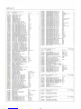
INDICE
/INDEX/
INHAL TSVERZEICHNIS / INDICE I SOMMAIRE
ITALIANO: da pag. 2 a pag. 6
Particolarita e innovazioni MTC911 O
Avvertenze . .
..
...
. . . .
....
. . . . .
Protezioni contro RX ........
..
.
..
.
Caratteristiche tecniche
.........
.
lnstallazione controllo e regolazione
lstruzioni operative
..
Comandi a distanza
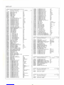
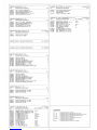
Parts list
........
. .
..
. . . . . . .
Schema . . . . . . . . . . . . . . . . . . . . . .
..
. . .
...
.
Circuito integrato TOA 2595 e TOA 1670A
..
. . .
..
.....
..
. . . . . . . .
Dati meccanici . . . . . . . . . . . . . . . . .
...
..
. . . . . . .
Taratura, tensioni e forme
d'onda
T.P. di controllo e forme
d'onda
. .
Connessioni e regolazioni dei trimmer
...
.
..
.
..
. . .
..
. . .
Inverter Video
...
.
..
.
..
. . . . . . . .
..
.
..
.
Accessori
...
.....
. . . . .
Prodotti complementari
ENGLISH: from page 7 to page
11
Details and innovations of the MTC9110
Warning
Protection against X-ray radiation . . . .
..
. .
..
. . .
Technical characteristics
Installation and setting-up instructions
Operating instructions
..
. .
...
. . . . . .
...
...
.
Monitor power input connexion schematic (U.S.A. only)
Remote control . . . . . . . . . . . . . . . .
...
. . .
..
. .
Parts list . . . . . . . . . . . . . . . . . . .
.....
.
Diagram
..
.
..
. .
..
. . . . . . .
Integrated circuits TOA 2595 and TOA 1670A
......
.. ..
. . . . .
Mechanical data .
..
...
.
..
.
Test points, voltages and waveforms
Control test points and waveforms
Connexions diagram and pre-set adjustments
Inverter Video
...
. . .
.. ..
.
Accessories .
..
.
.....
. . . . . . . . . . . . . . . . . .
..
. . .
..
.
..
..
.
Complementary products
...............
.
DEUTSCH: von Seite
12
bis Seite 16
Einzelheiten und Neuerungen des MTC9110
Bemerkungen -Warnungen
Vorbeugungsmassnahmen gegen Rontgenstrahlen
Technische Eigenschaften . . . . . . . . . .
....
.
Einbauanleitung, Kontrolle und Einstellungen
Arbeits-Anleitungen ·
Regler
fUr
die Fernbedienung
..
Parts list
Schaltbild
..
..
. .
..
. . . . .
......
.
Blockschaltbild fur TOA 2595 und TOA 1670A
Mechanische Angaben
....
...
.
....
..
.
.....
.
Test-Punkte, Sollspannungen, und Oszillatordiagramme
Test-Punkte und Oszillatordiagramme
..
. . .
..
.
............
.
AnschluBplan und Justage -Elemente
Video -Inverter -Baustein
ZubehOr
Zusa.tzlieferprogramm
ESPANOL: de pag. 17 a pag.
21
Caracteristicas e innovaciones del MTC9110
.........
.
Advertencias . . . . . . . . . . . . . . . . . . . . . . . .
..
. . . .
..
.
Proteccion contra rayos X
....
..
. . .
....
..
. . . .
Caracteristicas tecnicas . . . .
..
. .
..
. . . .
...
.
Procedimiento de instalacion, control y reajuste
lnstrucciones operativas . . . . . . . . . .
Mando a distancia
Parts list . . .
.. ..
...
.
Esquema
........
. .
..
.
Circuito lntegrado TOA 2595 e TOA 1670A
Datos mecanicos
...
..
. .
..
...
.
.......
.
Punto de medida, tension y forma de onda
Punto de prueba para control y forma de onda
Conexionado y regulacion de los potenciometros
lnversor de video
...
.....
..
. .
..
. . .
..
.
........
..
. . .
Accesorios . .
..
..
...........
.
Productos complementarios
FRAN<;:AIS:
de
la
page 22 a
la
page 26
Particularites et innovations MTC9110 .
..
. . . .
..
.....
..
. .
..
. .
..
.
Avertissements
..
. . . . . . . . .
..
...
.
Protection contre les rayons X
Caracteristiques techniques
..
Procede d'installation, controle et reglage
Mode operatoire
.. ..
. . .
..
...
.
Commandes a distance
Parts list
..
Schema
....
. . . . . . .
Circuits imprimes TOA 2595 et TOA 1670A
Donnees mecaniques . . .
....
. . . .
..
.
..
.
..
.
.....
.
Point de reglage tension et forme
d'onde
...
....
. . .
Points de test de controle et forme
d'onde
..
.
....
. . .
Schema de connexion et regulation des trimmers
..
Inverter Video . .
...
...
..
.
..
.
..
.
Accessoires
...
.
...
. . . . . .
....
...
..
. . . .
Produits additionnels
pag. 2
3
3
4
5
6
6
))
27
))
31
))
33
» 34
))
35
))
36
))
37
))
39
))
40
))
41
page 7
8
8
9
10
11
11
11
29
31
33
34
35
36
37
39
40
41
Seite 12
13
13
14
15
16
16
))
27-29
31
33
34
35
36
37
39
40
41
pag. 17
18
18
19
))
20
))
21
))
21
))
27-29
))
31
))
33
))
34
))
35
))
36
))
37
))
39
))
40
))
41
page 22
))
23
))
23
))
24
))
25
))
26
))
26
))
27-29
))
31
))
33
))
34
))
35
))
36
))
37
))
39
))
40
))
41

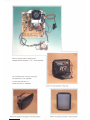
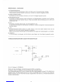
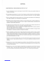
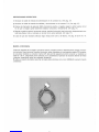
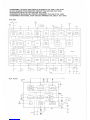
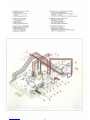
MTG
9110 piastra madre I Mother board
Assieme zoccolo cinescopio I
G.R.T.
socket assembly
Per
la
richiesta (base + zoccolo cinescopio)
fare riferimento al cod. 63200580
To
order base plate and c.r.t.
socket quote
part
no. 63200580
MTG
911
O posizione orizzontale I Horizontal position
\
MTG 9110 vista posteriore I Rear view
MTG
9110 posizione verticale I Vertical position

IT
ALIANO
PARTICOLARITA E INNOVAZIONI MTC9110
25"-28"
1)
II
monitor MTC911 O e stato progettato per
una
grande versatilita che gli consente di essere utilizzato
con qualsiasi
scheda
logica.
2) La piastra base, realizzata su un unico circuito stampato, e assemblata
da
macchine automatiche
che, non
commettendo
errori, garantiscono una grande uniformita di produzione e una maggiore
affidabilita.
3) Nuova e
completa
progettazione della parte meccanica al fine di renderla piu resistente alle sollecita-
zioni, (urti, cadute, trasporto, ecc.) risolvendo completamente i problemi relativi.
4) Adozione di
due
connettori (posizione CL/CM sul circuito stampato) per
l'unita
di deflessione (giogo)
con connessioni incrociate che permettono di invertire l'immagine nei
due
sensi; caratteristica indi-
spensabile in determinate applicazioni.
5) L'elettronica dei monitors
25"-28"/110°
utilizza un termostato fissato sull'aletta di raffreddamento (la-
to
TR
BU 508)
che
garantisce un eccezionale grado di sicurezza e affidabilita del prodotto.
Questa termostato interviene quando la temperatura sul dissipatore raggiunge i
75°/80°
interrompen-
do l'alimentazione (130 Vdc) avvisando cosl l'operatore dell'anomalia. Questa caso potrebbe verifi-
carsi nella remota ipotesi di bloccaggio del ventilatore o
in
un monitor che lavori in condizioni ambien-
tali veramente esasperate.
6)
Tutte le regolazioni che agiscono
sull'immagine
(frequenza orizzontale, frequenza verticale, ampiez-
za verticale,
ampiezza
orizzontale, fase orizzontale, centratura verticale), sono montate su una picco-
la scheda collegata alla piastra base tramite un connettore; su richiesta viene fornito un cavo della
lunghezza di m. 1,5 che permette di posizionare i suddetti comandi
in
modo
che l'operatore possa
agevolmente regolare
l'immagine
guardando
ii
video direttamente.
7)
Utilizzo, nel circuito di ingresso video, di uno speciale triplo potenziometro di precisione onde pater
adattare
ii
monitor a varie sorgenti di segnale (da 1 a 5 V.p.p.) senza problemi di indesiderate variazio-
ni di colore.
8) Adozione di un nuovo circuito integrato per la deflessione verticale (TOA 1670A) che permette di otte-
nere un breve tempo di ritorno verticale (0,7 ms) estendendo cosl le possibilita di impiego
ai
casi dove
questa prestazione e richiesta.
9) Adozione di un nuovo circuito integrato relativo all'elaborazione del sincronismo orizzontale e oscilla-
tore. Questa C.I., fra l'altro, garantisce una sicura protezione contra i raggi X, conformemente alle
principali
norme
internazionali sulla salute pubblica. (es. F.D.A. Federal Drug Administration).
2

AVVERTENZE
1)
ALIMENTAZIONE
L'alimentazione del monitor (128 Vac) deve essere connessa con
un
trasformatore separatore di rete.
2)COLLEGAMENTI
DI
MASSA
II
telaio e i dissipatori sono collegati a massa. Per
le
misure
di
tensione e forme d'onda connettere
i terminali negativi degli strumenti
al
telaio.
3)
RAGGI X
II
telaio e stato progettato per evitare l'emissione di raggi
Xe
comunque uno speciale circuito
di
sicu-
rezza garantisce che persino
in
caso di guasto la radiazione non superi mai 0,5 mR/h.
4)
E.A.T.
II
monitor ha nel proprio interno sorgenti di alta tensione pericolose per l'incolumita personale. Quin-
di, per utilizzare l'apparecchiatura senza pericolo per l'operatore, attenersi alle precauzioni qui di se-
guito descritte.
5) C.R.T.
II
tubo a raggi catodici e
un
componente
ad
alto vuoto e
le
sue superfici sono soggette a forti pressioni
esterne. E necessario percio aver cura di non urtare
ii
tubo perche questo potrebbe causare implosio-
ne.
Ne
consegue che
ii
personale responsabile dell'installazione deve usare guanti
ed
indumenti pro-
tettivi contra
le
schegge durante
le
operazioni di montaggio o
le
eventuali sostituzioni.
6)
PRECAUZION E
Per prevenire
la
possibilita
di
scariche elettriche non esporre
ii
monitor alla pioggia o all'umidita.
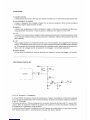
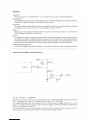
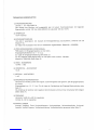
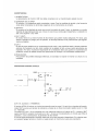
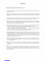
PROTEZIONI CONTRO
RX
+12V
1------<1~---
C35
22µF
PIN
8 D 10
TDA2595
(D.H.H.S. accession
n.
8720899-05)
017
PIN
10
i--~--~---~~-[J
TH2
II
monitor MTC911 O include
un
circuito
di
protezione per i raggi
X.
Una tensione di riferimento prelevata
da
un
impulso del t'rasformatore EAT e inviata attraverso
un
partitore di tensione resistivo
al
piedino
n.
8 dell'l.C. TOA 2595.
La tensione
al
piedino
n.
8 viene comparata con
un
preciso riferimento all'interno dell'l.C.; quanta l'EAT
supera i 30KV la variazione di tensione
al
piedino 8 fa scattare
un
circuito che inibisce
l'osci~latore
e
di
conseguenza
ii
generatore di alta tensione.
II
circuito continua a bloccare l'oscillatore fino
ache
ii
guasto
none
stato riparato.
In
ogni caso
ii
monitor
deve essere prima spento e successivamente riacceso per essere riattivato.
3

CARATTERISTICHE TECNICHE
1)
ALIMENTAZIONE
128Vac+10-10%
50/60 Hz
L'alimentazione del monitor deve essere fornita d1
a
un
trasformatore di alimentazione separatore di
rete avente
le
seguenti caratteristiche: primario 120 Vac (USA) 220/240 Vac; secondario 128 Vac
150
W.
2)
CONSUMO
100 W MAX.
3)
SMAGNETIZZAZIONE
100 7 264 Vac automatica.
Per avere
ii
circuito di smagnetizzazione con comando manuale eliminare
ii
ponticello P34
ed
inseri-·
re
nel connettore (CD)
un
cablaggio di lunghezza desiderata con
un
interruttore o
un
pulsante che
permetta l'intervento del circuito ogni volta che
se
ne
presenti la necessita.
4)
INGRESSO SEGNALI VIDEO
RVS positivo con impedenza d'ingresso
di
2,2 Kohm. Sensibilita di ingresso da 1 a 5 V.p.p. Per
le
posizioni dei cablaggi ingresso segnali vedi pag.
37.
Perun ingresso segnali video del tipo negato vedi
ii
circuito aggiuntivo «INVERTER-VIDEO» pag.39.
5)
BANDA PASSANTE VIDEO
12 MHz
-3
dB.
6)
SPEGNIMENTO ORIZZONTALE
12
us.
7)
SPEGNIMENTO VERTICALE
1 mS.
8)
INGRESSO SINCRONISMI
Orizzontale e verticale, positivo o negato, composito o separato. lmpedenza d'ingresso 2,2 Kohm.
Livello d'ingresso da 1,5 a 5 V.p.p. Per
le
posizioni dei cablaggi nel connettore ingresso segnali vedi
pag.
37.
La selezione del sincronismo positivo o negato e possibile agendo sul deviatore SW4. (Vedi pag. 37).
9)
FREQUENZA DELLE SCANSION!
Orizzontale 15.625
Hz.±
500
Hz:
regolabile.
Verticale 45 7
65
Hz:
regolabile.
10)
REGOLAZIONI
Contrasto, luminosita, fuoco, frequenza orizzontale, fase orizzontale ampiezza orizzontale, linearita
orizzontale, frequenza verticale, spostamento verticale, ampiezza verticale. Per maggiori dettagli vedi
pag.
37.
4

PROCEDURA
DI
INSTALLAZIONE, CONTROLLO E REGOLAZIONE
1)
ALIMENTAZIONE
Controllare la tensione
di
alimentazione del monitor sul
TP1
O;
ii
valore deve essere
di
130 Vdc ± 3%.
2)
OSCILLATORE ORIZZONTALE
Sincronizzare
la
frequenza orizzontale del monitor togliendo i sincronismi
(si
puo usare allo scopo
SW4) e ruotare
RVS
cercando di avere l'immagine video piu ferma possibile, quindi ripristinare i ·
sincronismi.
3)
OSCILLATORE VERTICALE
Girare
RV1
fino
al
punto di ottenere
un
leggero scorrimento verso
ii
basso dell'immagine; tornare
indietro fino a bloccare
lo
scorrimento.
4)
ALIMENTAZIONE DEL CIRCUITO DEFLESSIONE VERTICALE
Controllare
la
tensione di alimentazione dello stadia di deflessione verticale che deve essere
di
26
Vdc ±
5%
(TP13). (vedi pag.
35).
5)
ALIMENTAZIONE DEL CIRCUITO AMPLIFICATORE VIDEO
Controllare la tensione di alimentazione dello stadia amplificatore video che deve essere di
24
Vdc
± 5%
(TP1
).
(Vedi pag.
35).
6)
ALIMENTAZIONE DEL CIRCUITO FINALE VIDEO
Controllare la tensione di alimentazione dello stadia finale video che deve essere di 200 Vdc ± 5%
(TP14). (Vedi pag.
35).
7)
TARATURA BOBINA PONTE
La bobina ponte (B3) e gia tarata nelle nostre sedi produttive, ma
se
venisse erroneamente starata
con
lo
spostamento del nucleo
in
ferrite, seguire queste operazioni per rimetterla perfettamente a
punto:
a)
Regolare
al
minima l'ampiezza orizzontale col trimmer (RV4) sulla scheda CG.
b)
Girare
ii
nucleo della bobina B 3 fino
ad
ottenere la minima ampiezza orizzontale;
in
questo modo
la
bobina e perfettamente tarata.
c)
Riportare l'ampiezza orizzontale con RV4 alla larghezza desiderata.
8)
TARATURA DEL CIRCUITO EST/OVEST
Girare
ii
trimmer
RV401
sul modulo
KK
(vedi pag.
37)
per ottenere
la
migliore geometria verticale.
9)
REGOLAZIONE DELLO STADIO FINALE VIDEO GUADAGNI R.V.B.
Dopa aver inserito
un
segnale video R.V.B., ruotare a meta corsa
ii
comando regolazione guadagno
del blu (RV206) situato sull'assieme zoccolo cinescopio
ZG
e misurare con l'oscilloscopio
ii
valore
del segnale video sul relativo catodo portandolo a 100 V.p.p. mediante
ii
controllo del contrasto
(P1
);
portare
ii
segnale dei catodi rosso e verde allo stesso valore mediante i relativi controlli di guadagno
(RV202 e RV201). (Vedi pag.
37).
10)
TARATURA DEL BIANCO
a)
Togliere
ii
segnale video
in
ingresso.
b)
Porre alla massima luminosita la regolazione della griglia 1 (RV?).
c)
Ruotare
la
regolazione
dei
controlli
di
livello del nero
al
minima (senso orario) (RV203 rosso, RV204
verde, RV205 blu) situati sull'assieme zoccolo cinescopio
ZG.
d)
Diminuire la regolazione della griglia 2 (screen) situata sul trasformatore di riga TH2, lasciando
appena visibile
ii
colore del cannone dominante, quindi regolare i controlli
di
livello del nero fino
ad
ottenere
ii
miglior bianco possibile.
e)
II
potenziometro «Screen» ha la funzione di controllo della luminosita.
11)
FUOCO
Regolare
ii
fuoco (FOCUS situato sul trasformatore di riga TH2) usando
un
segnale con pagina
di
punti, con luminosita media, fino
al
miglior risultato visivo.
12)
LINEARITA ORIZZONTALE
Regolare, inserendo
un
segnale avente
un
reticolo,
ii
primo quadrato a destra uguale all'ultimo a
sinistra.
5

ISTRUZIONI OPERATIVE
1) lnserire
ii
cablaggio ingresso alimentazione
al
connettore
CC.
(vedi pag. 37).
2)
lnserire
ii
cablaggio ingresso segnali e sincronismi
al
connettore C.A. (vedi pag. 37).
3)
Posizionare
lo
switch di selezione SW4 sincro positive o negato secondo
ii
segnale usato, affinche
l'immagine sia perfettamente stabile orizzontalmente e verticalmente. (vedi pag. 37)
4)
Regolare: ampiezza verticale, frequenza verticale, ampiezza orizzontale, fase orizzontale, spostamento
verticale, frequenza orizzontale, Est-Ovest, luminosita e contrasto
in
funzione del segnale applicate.
(vedi pag. 37). ·
Per eventual1 ritocchi del colore e del bianco vedi pag. 5 punto 9 e 10.
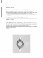
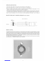
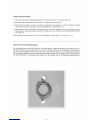
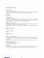
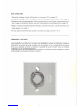
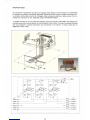
COMANDI A DISTANZA
Tutte
le
regolazioni dell'immagine: frequenza verticale, ampiezza verticale, spostamento verticale, fre-
quenza orizzontale, fase orizzontale, ampiezza orizzontale, sono montate
su
una piccola scheda (CG)
collegata alla piastra tramite
un
connettore maschio (CF); cio consente di poterla sfilare dal suddetto
connettore
e,
tramite
un
cablaggio
di
m 1,50 (fornibile
su
richiesta), da
la
possibilita all'operatore
di
por-
tarsi davanti
al
video e operare visivamente tutte
le
necessarie regolazioni.
II
cablaggio e
ii
supporto
in
plastica per
ii
fissaggio della scheda deve essere richiesto con cod. 62008440
«assieme comando a distanza».
(Vedi foto)
- I
6

ENGLISH
DETAILS AND INOVATIONS
OF
THE MTC 9110 -
25"-28"
1)
The MTC 9110 monitor has been designed for maximum versatility,
so
allowing
it
to
be
used with almost
any logic board.
2)
The 'monolithic' construction, using a single printed circuit board, makes maximum use
of
the automatic
insertion of components, which, being free of human error, guarantees a high level of production
uniformity coupled with a high level of reliability.
3)
Completely new mechanical design with the specific object of making the unit extremely resistant to
impact and vibration during transportation.
4)
Use
of two connectors (CL and
CM
on
the printed circuit board) for the deflexion unit with cross-over
wiring which permits easy inversion and reversal of the image -often
an
indispensable feature.
5)
The electronics for the
25"-28"/110°
incorporates a thermostat mounted
on
the heat sink
(on
the side
of TR
BU
508) which guarantees
an
exceptionally high degree of product safety and reliability.
The thermostat comes into operation if its temperature reaches 75-80°, interrupting the 130 V d.c.
supply so bringing the fault
to
the attention of the operator. This could happen if, for example, the
ventilator failed, or the monitor were used
in
conditions of extreme ambient temperature.
6)
All the controls which affect the display (horizontal and vertical frequency, horizontal and vertical
amplitude,
horizon_tal
phase and vertical shift) are mounted
on
a small separate p.c.b. which
is
normally
plugged into a connector
on
the main board, but may
be
used
in
conjunction with a 1.5 metre long
extension cable that
is
available
on
request. This allows the control card to
be
mounted
in
a specially
moulded mounting bracket
in
a position where the operator can easily adjust the monitor while directly
viewing the image.
7)
The video input is fed via a precision three-gang potentiometer permitting acceptance of input signals
in
the range 1 to 5 V p.p. without creating changes
in
colour balance.
8)
Utilization of a new integrated circuit for vertical deflexion
(TOA
1670A) resulting
in
the short vertical
fly-back time of 0.7 ms,
so
extending the range of logic board usage.
9)
Incorporation of a new integrated circuit
in
the horizontal sync. circuitry. This l.C. guarantees a positive
protection against x-ray radiation and conforms with the principal international public health regulations,
such
as
F.D.A. Federal Drug Administration.
7

WARNING
1)
SUPPLY
The input supply of the monitor (128 V a.c.) must be fed via a mains isolating transformer.
2)
EARTHING
The chassis and the heat sinks are connected to earth. To measure voltages and to inspect waveforms,
connect the negative terminals of instruments to the chassis.
3) X-RAYS
The monitor has been designed to minimize x-ray radiation. Furthermore, a special safety circuit comes
into operation
in
the event of failure to limit radiation to below 0.5 mR/h.
4) E.H.T.
Dangerously high voltages are present inside the monitor, and for safe operation it
is
imperative to
follow all safety instructions and warnings.
5) C.R.T.
The cathode-ray tube
is
a high vacuum device and its surfaces are subject to high external pressure.
It
is
therefore necessary to handle the tube with care and to avoid impact which could cause implosion.
It follows that personnel handling cathode-ray tubes during installation or during replacement, should
wear thick gloves and protective clothing to protect against possible flying glass splinters.
6)
WEATHER PROTECTION
To avoid the possibility of electric discharge, do not expose the monitor to rain or excessive humidity.
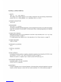
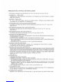
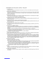
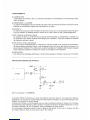
PROTECTION AGAINST X-RAY RADIATION
+
12V
1-------11~--..,.._
C35
22µF
PIN
8 0 10
TOA2595
(D.H.H.S. accession
n.
8720899-05)
017
PIN
10
~~~----~~[]
TH2
1%
,J_,
C45
I
1u
The MTC
911
O monitor contains
an
x-ray protection circuit. A reference voltage
is
generated from the
E.H.T. transformer and
is
fed via a resistive divider to pin 8 of l.C. TDA 2595.
The voltage appearing at pin 8
is
compared with an accurate reference voltage within the l.C., and if
the E.H.T. exceeds 30 kV the voltage at pin 8 operates a trigger circuit which inhibits the oscillator and
hence the generation of the E.H.T.
The circuit continues to block the oscillator until the cause of the failure has been repaired, and can
only be reset by completely switching-off the monitor and switching-on again.
8

TECHNICAL CHARACTERISTICS
1)
SUPPLY
128 V a.c. + 10
-10%,
50/60 Hz
The supply to the monitor must be via
an
isolating transformer with the following characteristics:
primary 120 V a.c. (USA) 220/240 V a.c., secondary 128 V a.c. 150
W.
2)
POWER CONSUMPTION
100
W.
max.
3)
DEGAUSSING
100-:- 264 V a.c. automatic.
To change
to
manually controlled degaussing, remove bridge
P34
and insert a twin cable of the desired
length into connector
CD
terminated
in
a push-button switch, enabling degaussing
to
be
effected
at any time.
4)
VIDEO INPUT SIGNALS
RGB positive-going with
an
input impedance of 2.2 kOhm. Input sensitivity from 1
to
5 V p.p. Input
connexions
as
shown
on
page
37.
For negative-going input signals refer to the description of the «Video Inverter»
on
page
39.
5)
VIDEO PASS BAND
-3
dB
at
12 MHz
6)
HORIZONTAL BLANKING
12
us
7)
VERTICAL BLANKING
1
ms
8)
SYNC. SIGNALS
Horizontal and vertical, positive or negative, composite or separate. Input impedance 2.2 kOhm. Input
level between 1.5 and 5 V p.p. Input connexions
as
shown
on
page
37.
Selection of positive or negative input
is
made by switch SW4 (see page 37).
9)
SCANNING FREQUENCIES
Horizontal 15.625 ± 0.5 kHz: adjustable.
Vertical 45-65
Hz:
adjustable.
10)
CONTROLS
Contrast, brightness, focus, horizontal frequency, horizontal phase, horizontal amplitude, horizontal
linearity, vertical frequency, vertical shift and vertical amplitude. For further details see page
37.
9

INSTALLATION AND SETTING-UP INSTRUCTIONS
1)
SUPPLY
Check that the h.t. line voltage of the monitor at test point
TP1
O
is
130 V d.c. ± 3%.
2)
HORIZONTAL OSCILLATOR
Remove the incoming sync. signal (for which one may use SW4) and turn
RV5
to obtain a stationary
image. Reconnect the sync. input signal.
3)
VERTICAL OSCILLATOR
Adjust
RV1
to obtain a slow roll-over of the image
in
a downward direction. Turn back until the image
locks.
4)
FEED VOLTAGE TO VERTICAL DEFLEXION CIRCUIT
Check that the voltage at TP13
is
26
V d.c. ± 5%. See page
35.
5)
FEED VOLTAGE TO VIDEO AMPLIFIER
Check that the voltage
at
TP1
is
24 V d.c. ± 5%. See page
35.
6)
FEED VOLTAGE TO VIDEO OUTPUT AMPLIFIER
Check that the voltage at TP14
is
200 V d.c. ± 5%. See page
35.
7)
ADJUSTMENT OF BRIDGE COIL
Bridge Coil B3
is
adjusted
on
the production line, but should
it
become necessary to re-adjust, the
following procedure should
be
adopted:
a)
Adjust RV4
on
board
CG
for minimum horizontal amplitude.
b)
Adjust the ferrite core of
B3
for minimum horizontal amplitude.
c)
Re-adjust RV4 to obtain the desired amplitude.
8)
ADJUSTMENT OF EAST/WEST CIRCUIT
Adjust pre-set resistor
RV401
on
module
KK
(see page
37)
to obtain the best vertical geometry.
9) ADJUSTMENT OF GAIN OF RGB VIDEO OUTPUT STAGES
Having inserted RGB signals of equal amplitude
to
the inputs, turn the blue gain control RV206, lo-
cated
on
the c.r.t. neck board
ZG,
to its mid-position and adjust the Contrast Control
P1
so
that the
video signal measured with
an
oscilloscope at the blue cathode
is
100 V p.p. Adjust the signals at
the cathodes of the
red
and green guns
to
the same value by adjustment of RV202 and
RV201
.
See page
37
.
10) ADJUSTMENT OF
«WHITE»
a)
Remove the video input signal.
b)
Turn RV7
on
the c.r.t. grid
1,
to maximum brightness.
c)
Turn the black level controls situated
on
the c.r.t. neck board, RV203 red, RV204 green and RV205
blue, to minimum (clockwise).
d)
Reduce the brightness by adjusting the voltage
on
grid 2 by means of the control situated
on
the
line output transformer TH2
so
that the dominant colour
is
only just visible, and then adjust the black
level controls to obtain the best white possible.
e)
The G2 «Screen» potentiometer functions
as
the brightness control.
11)
FOCUS
Adjust the focus control (FOCUS situated
on
the line output transformer TH2) using a dot pattern
signal, with medium brightness, to give the best focus obtainable.
12)
HORIZONTAL LINEARITY
Using a grid pattern signal, adjust for the last square
on
the right to
be
equal
in
size to the first square
on
the left.
10

OPERATING INSTRUCTIONS
1)
Insert the supply cable
to
the power input connector
CC.
See page
37.
2)
Insert the signal and sync. cable to the input connector
CA.
See page
37.
3)
Set sync. selector switch SW4
to
positive or negative according
to
the type of input signal.
~o:
As
to
obtain a locked image horizontally and vertically. See page
37.
4)
Next adjust vertical amplitude, vertical frequency, horizontal amplitude, horizontal phase, vertical shift,
horizontal frequency, East-West, brightness and contrast
to
match the applied signal. See page
37.
Finally
it
may
be
necessary
to
trim
to
the colour and white adjustments. See para. 9 and 1 O page 1
O.
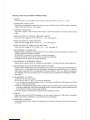
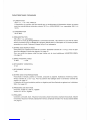
MONITOR POWER
INPUT
CONNEXION SCHEMATIC (U.S.A. ONLY)
FOR U.S.A.
Isolation
Irons
former
-----
REMOTE CONTROL
MAINS CONNECTION
PIN
I
PIN 4
The following controls are all mounted
on
a small printed circuit board
CG:
vertical frequency, vertical
amplitude, vertical shift, horizontal frequency, horizontal phase, horizontal amplitude. The board
is
fitted
with a socket connector which
is
plugged into a mating plug connector CF
on
the main board, and may
be
removed and re-connected via a 1.5 metre cable (available
on
request) enabling the operator
to
adjust
all those controls from the front of the monitor.
The cable and the special plastic support frame for remotely mounting the control board can
be
ordered
by quoting part no. 62008440 Remote Control Assembly.
11

DEUTSCH
EINZELHEITEN
UNO
NEUERUNGEN
DES
MTC9110
25"-28"
1)
Der Monitor MTC911 O wurde
fUr
eine groBtmogliche Vielseitigkeit geplant, welche
es
ermoglicht, ihn mit
jeder Art von Video-spielplatinen
zu
betreiben.
2)
Das Grundchassis, besteht aus einer Hauptplatine, die automatisch gefertigt wird. Dadurch wird eine
groBe Zuverlassigkeit
in
der Produktion und damit eine ausgezeichnete Qualitat erreicht.
3)
Der neue und kompakte Aufbau des mechanischen Teils machen den Monitor widerstandstahig gegen-
Ober
Beanspruchung und Belastung bei
StoB,
Fall und Transport.
4) Die Verwendung von zwei Steckverbindungen (Position CL/CM auf der Platine), erlauben die Um-
kehrung der Ablenkung
um
180 Grad. Eine unentbehrliche Eigenschaft
bei
bestimmten Anwendungsfal-
len.
5)
Die Electronic
fUr
Monitore mit
25"-28"
Bilddiagonale, sowie 110 Grad -Ablenkung ist mit einem Ther-
mostat ausgestattet. Dieses befindet sich auf dem Kuhlblech des Transistors
BU
508, wodurch eine
Ober-
hitzung vermieden wird und ein HochstmaB
an
Betriebssicherheit gewahrleistet.
Das Thermostat spricht bei einer erreichten Temperatur zwischen
75
und
80
Grad Celsius
an
und unter-
bricht die 130 V D.C.-Spannungsversorgung.
Diese Schutzschaltung reagiert z.B. auf einen fehlerhaften Ventilator oder Oberschreibung der Betriebs-
temperatur.
6)
Samtliche Bildeinstellungen, (Horizontal -und Vertikalfrequenz, Vertikal -und Horizontalamplitude,
Horizontalphase + Vertikalzentrierung) sind auf einer kleinen Leiterplatine untergebracht, welche
Ober
eine Steckverbindung mit der Grundplatine verbunden ist.
7)
Auf Anforderung kann
ein
1,5 m langes Kabel geliefert werden, welches die Verbindung zur Reglerplatine
herstellt, die dadurch bediengerecht eingebaut werden kann.
Im
Video-Eingangskreis findet ein 3-fach
Potentiometer Verwendung, das als
DC
Kopplung arbeitet. Samit kann der Monitor
an
verschiedene
Si-
gnalquellen (von 1 bis 5 Vpp.), ohne das Problem von unerwunschten Farbverschiebungen, angepaBt
werden.
8)
Durch eine neuartig integrierte Schaltung
fUr
die Vertikalablenkung (TDA 1670A) ergibt sich eine kurze
Vertikal-ROcklaufzeit von (0,7 ms). Dadurch vergroBern sich die Anwendungsbereiche, bei denen diese
Leistungen gefordert werden.
9)
Verwendung der neuartigen Schaltung des
IC
TDA 2595
im
Schaltkeis
fUr
die horizontale Synchronisation.
Sie garantiert einen Sicherheitsschutz gegenuber Rontgenstrahlen, nach den wichtigsten Richtlinien
internationaler Gesundheitsvorschriften, (F.D.A. Federal Drug Administration und Rontgenverordnung).
12

BEMERKUNGEN -WARNUNGEN
1)STROMVERSORGUNG
Die Stromversorgung des Monitors (128
V)
muB
uber einen Trenntransformator erfolgen.
HierfUr konnen auch die Netzteile
US
250 bzw.
US
300 von Hantarex eingesetzt werden.
2)
MASSE-VERBINDUNGEN
Der Rahmen ist mit der Masse verbunden und
muB
im
Fertiggerat geerdet werden.
3)RONTGENSTRAHLEN
Der Monitor ist derart konstruiert, dass die Emission von Rontgenstrahlen vermieden wird. Ein Sicher-
heitsstromkreis garantiert daruber hinaus
im
Falle eines Defekts,
daB
die Strahlung von 0,5 mR/h nicht
uberschritten wird.
4)
E.H.T.
Der Monitor verarbeitet Spannungen, die lebensgefahrlich sind.
Um
das Gerat ohne Gefahr
fUr
den Benutzer
zu
bedienen, mussen die folgenden VorsichtsmaBnahmen
beachtet werden.
5) C.R.T.
Die Kathodenstrahlen-Rohre besitzt ein groBes Vakuum, somit wirkt starker auBerer Druck auf die
Bildrohre ein.
Es
ist sehr wichtig, folgendes
zu
beachten:
St6Be
und mechanische Einwirkungen auf der Bildrohre sind wegen der lmplosionsgefahr
zu
vermeiden.
6)
VORSICHT
Um
Kurzschlussen vorzubeugen, darf der Monitor weder Regen noch Feuchtigkeit ausgesetzt werden.
VORBEUGUNGSMASSNAHMEN GEGEN RONTGENSTRAHLEN
+
12V
1----i.-----
C35
22µF
PIN
8 0 10
TOA2595
(D.H.H.S. Beilage
N.
8720899-05)
017
PIN
10
~--it--~--~-[]
TH2
Hierbei sind die einschlagigen Unfallverhutungsvorschriften
zu
beachten.
Der Monitor MTC911 O besitzt eine Schutzschaltung gegen Rontgenstrahlen.
Varn
Zeilentransformator (EAT) wird ein lmpuls uber einen Spannungsteiler
an
das
IC
TDA 2595 (Pin
8)
angelegt. Sofern die Referenzspannung
am
Pin 8 einen unzulassigen Wert von
30
KV
an
der Anode der
Bildrohre feststellt, wird der horizontale Oszillator abgeschaltet. Das Gerat ist zur Wiederinbetriebnahme
zunachst auszuschalten.
13

TECHNISCHE EIGENSCHAFTEN
1)STROMVERSORGUNG
128 Vac +
10-10%
50/60 Hz
Das Netzteil des Monitors
muB
ausgestattet sein mit einem Trenntransformator mit folgenden
Eigenschaften: primar 120 Vac (USA) 220/240 Vac sekundar 128 Vac 150
W.
2)
VERBRAUCH
100 W maximal.
3)
ENTMAGNETISIERUNG
1oo-7-264 v automatisch.
Um
manuell die Entmagnetisierung durchzufUhren, entfernen Sie die
Brucke P
34.
Ein Kabel mit Drucktaster wird hier
am
CD-Stecker angeschlossen. (Bestell-Nr.: 61000300)
4)
VIDEO-EINGANGSKREIS (VIDEO-SIGNAL)
RGB positiv mit Eingangsimpedanz von 2,2 Kohm.
Eingangsempfindlichkeit von 1 - 5 V.p.p.
Zur Lage der Eingangsverkabelung siehe Seite 37.
Fur ein negatives Video-Signal liefern wir als Option einen Inverter -Baustein.
(Bestell-Nr. 63000160) Siehe Seite 39.
5)
VIDEO -BANDBREITE
12
MHz - 3 dB.
6)
HORIZONTAL -AUSTASTZEIT
12
us.
7) VERTIKAL -AUSTASTZEIT
1 mS.
8)
EINGANGS-SYNCHRONISATION
Horizontal und Vertikal, positiv oder negativ, zusammengesetzt oder getrennt. (Die Eingangsimpedanz
2,2 Kohm).
Eingangspegel von 1,5 - 5 V.p.p. Fur die Lage der Verkabelung des Eingangs-Steckverbinder siehe
Seite 37.
Die Aufteilung der positiven oder negativen Synchronisation wird durch den Umschalter SW4 moglich
(Siehe Seite 37).
9) FREQUENZ
Horizontal 15.625
Hz±
500 Hz regulierbar
Vertikal
45
-7-
65
Hz regulierbar.
10) EINSTELLUNGEN
Kontrast, Helligkeit, Focus Horizontalfrequenz, Horizontalphase, Horizontalamplitude, Horizontal-
linearitat, Vertikal-Frequenz, Vertikalverschiebung, Vertikalamplitude, genaueres siehe Seite 37.
14

EINBAUANLEITUNG, KONTROLLE
UNO
EINSTELLUNGEN
1)
Kontrolle der Netzspannung des Monitors auf
TP
10, der Wert darf 130 Vdc ± 3% sein.
2)
HORIZONTAL -OSZILLATOR
Angleichung der Horizontalfrequenz des Monitors unter Wegnahme der Synchronisation
(zu
diesem
Zweck
RV
5 justieren).
3)
VERTIKAL -OSZILLATOR
RV
1 bis
zu
dem Punkt drehen,
daB
man ein leichtes Laufen
in
Richtung unterer Bildrand erhalt;
zuruckdrehen bis zum Stillstand der Laufbewegung.
4)
STROMK~EIS
DER VERTIKALABLENKUNGS-FREQUENZ
Kontrollieren der Spannung wahrend des Normalbetriebes die
26
Vdc ±
5%
an
TP
13
sein
muB.
Siehe Seite
35.
·
5)
BETRIEBS
.:
S
.
PANNUNG~N
DES
VIDEOVERSTARKERS
Kontrollieren der Spannung des Video-Verstarkers, welche
24
Vdc ± 5%
an
TP 1 sein
muB.
Siehe Seite
35.
6)
BETRIEBSSPANNUNG
DER
VIDEO-ENDSTUFE
Kontrollieren ·Sie wahrend des Betriebes 190 Vdc ±
5%
siehe Seite
35
TP14.
7)
EICHUNG DER BIL.DBREITENSPULE
Die Bildbreitenspule
(B3)
ist schon werkseitig geeicht, aber sollte eine Neueinstellung erforderlich sein,
ist folgendermaBen vorzugehen:
a)
mit Poti (RV4) auf der Platte
C<!l
die Horizontalweite auf Minimum bringen.
b)
den Kern der Spule
B3
drehen, bis
man
die kleinste Horizontalweite erhalt.
In
dieser Stellung ist die
Spule perfekt geeicht.
c)
Zurucktuhrung der Horizontalweite
von
RV4 auf gewunschte Bildbreite.
8)
ABGLEICH DES OST-WEST-MODUL
Um
die beste vertikale Geometrie
zu
erhalten, ist es notwendig den Trimmer
RV401
zu
drehen.
Er befindet sich auf dem Modul
KK.
Siehe Seite
37.
9)
EINSTELLUNG
DER
VIDEO-VERSTARKUNG
Nachdem das Video-Signal (R.G.B.) angelegt
ist,
den
Verstarkungs-Regler bis auf die Halfte
Blau
(RV206)
drehen, welcher sich auf der Bildrohrensockelplatine
(ZG)
befindet. Mit dem Oszillograph den Wert des
Video-Signals auf der entsprechenden Farb-Kathode messen und auf 100 V.p.p. einstellen. Gleichzeitig
Kontrast
(P1)
kontrollieren, das Signal der roten und grunen Kathoden auf den selben mittleren Wert
bringen und entsprechende Kontrollen beachten. (RV202 und
RV201
).
Siehe Seite
37.
10)
WEIB-ABGLEICH
a)
Eingangs-Video-Signal ausschalten.
b)
Regulierung des Gitters 1 (RV?) auf gr6Bte Leuchtkraft.
c)
Die
Schwarzwert-Regler auf Minimum drehen (RV203
Rot,
RV204 Grun, RV205 Blau). Sie sind auf
der Bildrohrensockelplatine
(ZG)
angebracht.
d)
Die
Gitter-2-Einstellung verkleinern (Screen). Sie befindet sich
am
Zeilentrafo TH2. Auf minimale
Helligkeit der Rohre, dann bis zum regularen Niveau des Schwarzwertes einstellen,
um
das best-
mogliche
WeiB
zu
erhalten.
e)
Die Helligkeitskontrolle
«Screen»
findet mit Sicht auf die Bildrohre statt.
11) FOCUSEINSTELLUNG
Regulierung der Focuseinstellung, Focus angebracht
am
Zeilentransformator TH2, mit Signalgenera-
tor (z.B. Hantarex K 190
G)
bis zum bestmoglichen Ergebnis.
12) HORIZONTALE-LINEARITAT
Regulieren durch Darstellung eines Gittermusters,
so
daB
alle Quadrate die gleiche
Gr6Ben
haben.

ARBEITS-ANLEITUNGEN
1)
Einstecken des Stromversorgungskabels durch Steckerverbinder
CC.
(Siehe Seite
37).
2)
Einstecken des RGB-Kabels (Siehe Seite 37.) durch Steckverbinder
CA.
3)
Schalter SW4
in
Position bringen, Syncnronisierung positiv oder negativ -je nach vorhandenem Signal
-bis das Bild perfekt horizontal und vertikal stabilisiert ist. (Siehe Seite
37).
4)
Einstellungen: Vertikal-Amplitude, Vertikal-Frequenz, Horizontal-Amplitude, Horizontal-Phase, Vertikal-
Verschiebung, Horizontal-Frequenz,Ost-West, Helligkeit und Kontrast auf optionale Bildqualitat bringen
siehe Seite
37.
Eventuelle Nachjustierung der Farbe und des WeiBwertes, siehe Seite
15
Punkten 9 und
10,
REGLER FUR DIE FERNBEDIENUNG
Alie Bildeinstellungen, wie Vertikal-Frequenz, Vertikal-Amplitude, Vertikal-Verschiebung, Horizontal-Frequenz,
Horizontal-Phase, Horizontal-Amplitude, sind auf einer kleinen Platine
(CG)
untergebracht. Die Platine ist
auf dem Chassis steckbar angebracht und gibt somit dem Benutzer uber ein 1,5 m langes Kabel (lieferbar
auf Anfrage) die Moglichkeit, vor dem Bildschirm alle notigen Einstellungen
zu
tatigen.
Das
Verbindungskabel
und der Plastikhalter zur Befestigung der (Platte) kann als Zubehor mit der
Nr.
62008440 bestellt werden.

ESPANOL
CARACTERISTICAS E INNOVACIONES DEL MTC9110
25"-28"
1)
La gran versatilidad de la que ha sido dotado
el
monitor MTC9110 hace que sea posible utilizarlo con
cualquier tarjeta
16gica.
2)
El
ensamblaje de la placa base,
en
un
(mica circuito impreso,
se
realiza a traves de una cadena robotiza-
da que,
al
no
cometer errores, garantiza una gran uniformidad de producci6n y una mayor fiabilidad.
3)
Nuevo y complete diseno de la parte mecanica con
el
fin de hacerla mas resistente a los incidentes (gol-
pes, cafdas, transporte, etc.) minimizando las consecuencias.
4)
Adaptaci6n de dos conectores (posici6n CL/CM
en
el
circuito impreso) para
la
unidad de deflexi6n (yu-
go)
con conexiones cruzadas que permiten invertir la imagen
en
ambos sentidos; caracterfstica indis-
pensable
en
determinadas aplicaciones.
5)
La
electronica de los monitores 25"-28"/110° incorpora
un
termostato sujeto
al
radiador
(al
lado del transf.
BU
508) este garantiza
un
alto nivel de seguridad y fiabilidad del producto.
Este termostato interviene cuando la temperatura
en
el
radiador alcanza 75°/80° cortando la alimenta-
cion de los 130V avisando asi de
la
anomalia.
Este caso puede darse con la remota posibilidad de que
se
bloqueara
el
ventilador o
en
algun monitor
que trabajara
en
condiciones extremas de temperatura ambiente.
6)
Todos los reajustes que actuan sabre
la
imagen (frequencia horizontal, frequencia vertical, amplitud
vertical, amplitud horizontal, fase horizontal, centraje vertical), estan instalados
en
una pequena tarjeta
co-
nectada a
la
placa base mediante
un
conector; previa solicitud,
se
facilita
un
cable de 1,5
m.
de largo
que permite colocar dichos mandos de manera que
el
operador pueda regular con toda facilidad
la
ima-
gen viendola directamente
en
el
vfdeo.
7)
Utilizaci6n,
en
el
circuito de entrada vfdeo, de
un
triple potenci6metro especial de precision para poder
adaptar
el
monitor a varias fuentes de senal (de 1 a 5 V.p.p.) sin problemas de cambios de color
no
deseados.
8)
Adaptaci6n de
un
nuevo circuito integrado para
la
deflexi6n vertical (TOA 1670A) que permite obtener
un
breve tiempo de retorno vertical (0,7 ms) ampliando asf las posibilidades de uso
en
los casos
en
que
se necesite esta prestaci6n.
9)
Adaptaci6n de
un
nuevo circuito integrado correspondiente a la elaboraci6n del sincronismo horizontal
y oscilador. Este C.I., entre otras cosas, garantiza una segura protecci6n contra los rayos
X,
conforme
a las normas basicas internacionales de salud publica (e.j.: F.D.A. Federal Drug Administration).
17
La page est en cours de chargement...
La page est en cours de chargement...
La page est en cours de chargement...
La page est en cours de chargement...
La page est en cours de chargement...
La page est en cours de chargement...
La page est en cours de chargement...
La page est en cours de chargement...
La page est en cours de chargement...
La page est en cours de chargement...
La page est en cours de chargement...
La page est en cours de chargement...
La page est en cours de chargement...
La page est en cours de chargement...
La page est en cours de chargement...
La page est en cours de chargement...
La page est en cours de chargement...
La page est en cours de chargement...
La page est en cours de chargement...
La page est en cours de chargement...
La page est en cours de chargement...
La page est en cours de chargement...
La page est en cours de chargement...
La page est en cours de chargement...
La page est en cours de chargement...
La page est en cours de chargement...
La page est en cours de chargement...
La page est en cours de chargement...
-
 1
1
-
 2
2
-
 3
3
-
 4
4
-
 5
5
-
 6
6
-
 7
7
-
 8
8
-
 9
9
-
 10
10
-
 11
11
-
 12
12
-
 13
13
-
 14
14
-
 15
15
-
 16
16
-
 17
17
-
 18
18
-
 19
19
-
 20
20
-
 21
21
-
 22
22
-
 23
23
-
 24
24
-
 25
25
-
 26
26
-
 27
27
-
 28
28
-
 29
29
-
 30
30
-
 31
31
-
 32
32
-
 33
33
-
 34
34
-
 35
35
-
 36
36
-
 37
37
-
 38
38
-
 39
39
-
 40
40
-
 41
41
-
 42
42
-
 43
43
-
 44
44
-
 45
45
-
 46
46
-
 47
47
-
 48
48


Hantarex MTC 9110 Manuel utilisateur
- Catégorie
- Téléviseurs
- Taper
- Manuel utilisateur
dans d''autres langues
- italiano: Hantarex MTC 9110 Manuale utente
Autres documents
-
 Videovox Pro GB Series Mode d'emploi
-
Comelit MT VCC 01 Technical Manual
-
NEC Diamond Pro 2040U Le manuel du propriétaire
-
Sony GDM-5402 Manuel utilisateur
-
-
-
-
IBM P260 Manuel utilisateur
-
-
