Flex FX1371A 24V BRUSHLESS IMPACT DRIVER Manuel utilisateur
- Catégorie
- Clés à chocs électriques
- Taper
- Manuel utilisateur

Model:
Modelo:
Modèle:
OPERATOR’S MANUAL
MANUAL DEL OPERADOR
MANUEL DE L’UTILISATEUR
833-FLEX-496
(833-3539-496)
For English
Version
See page 2
◆
Version
française
Voir page 20
◆
Versión en
español
Ver la página 40
www.Registermyex.com
Contact Us /
Nous contacter /
Contáctenos
24V BRUSHLESS IMPACT DRIVER
VISSEUSE À PERCUSSION SANS BALAI DE 24 V
ATORNILLADOR DE IMPACTO SIN ESCOBILLAS DE 24 V
FX1371A

-2-
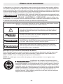
SAFETY SYMBOLS
The purpose of safety symbols is to attract your attention to possible dangers. The safety symbols
and the explanations with them deserve your careful attention and understanding. The symbol
warnings do not, by themselves, eliminate any danger. The instructions and warnings they give are
no substitutes for proper accident prevention measures.
WARNING Be sure to read and understand all safety instructions in this Owner's Manual,
including all safety alert symbols such as “DANGER,” “WARNING,” and
“CAUTION” before using this tool. Failure to follow all instructions listed below may result in electric
shock, re, and/or serious personal injury.
The denitions below describe the level of severity for each signal word. Please read the manual and
pay attention to these symbols.
This is the safety alert symbol. It is used to alert you to potential personal
injury hazards. Obey all safety messages that follow this symbol to avoid
possible injury or death.
DANGER DANGER indicates a hazardous situation which, if not avoided, will result in
death or serious injury.
WARNING WARNING indicates a hazardous situation which, if not avoided, could result
in death or serious injury.
CAUTION CAUTION, used with the safety alert symbol, indicates a hazardous situation
which, if not avoided, will result in minor or moderate injury.
Damage Prevention and Information Messages
These inform the user of important information and/or instructions that could lead to equipment or
other property damage if they are not followed. Each message is preceded by the word “NOTICE”,
as in the example below:
NOTICE: Equipment and/or property damage may result if these instructions are not followed.
WARNING The operation of any power tools can result in foreign
objects being thrown into your eyes, which can result in
severe eye damage. Before beginning power tool operation, always wear
safety goggles or safety glasses with side shields and a full face shield when
needed. We recommend a Wide Vision Safety Mask for use over eyeglasses
or standard safety glasses with side shields. Always use eye protection which
is marked to comply with ANSI Z87.1.

-3-
GENERAL POWER TOOL SAFETY WARNINGS
WARNING Read all safety warnings, instructions, illustrations and specications
provided with this power tool. Failure to follow all instructions listed below may
result in electric shock, re and/or serious injury.
SAVE ALL WARNINGS AND INSTRUCTIONS FOR FUTURE REFERENCE.
The term “power tool” in the warnings refers to your mains-operated (corded) power tool or battery-
operated (cordless) power tool.
Work area safety
Keep work area clean and well lit. Cluttered
or dark areas invite accidents.
Do not operate power tools in explosive
atmospheres, such as in the presence of
ammable liquids, gases or dust. Power
tools create sparks which may ignite the dust or
fumes.
Keep children and bystanders away while
operating a power tool. Distractions can cause
you to lose control.
Electrical safety
Power tool plugs must match the outlet.
Never modify the plug in any way. Do
not use any adapter plugs with earthed
(grounded) power tools. Unmodied plugs
and matching outlets will reduce risk of electric
shock.
Avoid body contact with earthed or
grounded surfaces, such as pipes, radiators,
ranges and refrigerators. There is an
increased risk of electric shock if your body is
earthed or grounded.
Do not expose power tools to rain or wet
conditions. Water entering a power tool will
increase the risk of electric shock.
Do not abuse the cord. Never use the cord
for carrying, pulling or unplugging the
power tool. Keep cord away from heat, oil,
sharp edges or moving parts. Damaged or
entangled cords increase the risk of electric
shock.
When operating a power tool outdoors, use
an extension cord suitable for outdoor use.
Use of a cord suitable for outdoor use reduces
the risk of electric shock.
If operating a power tool in a damp location
is unavoidable, use a ground fault circuit
interrupter (GFCI) protected supply. Use of a
GFCI reduces the risk of electric shock.
Personal safety
Stay alert, watch what you are doing and
use common sense when operating a power
tool. Do not use a power tool while you are
tired or under the inuence of drugs, alcohol
or medication. A moment of inattention while
operating power tools may result in serious
personal injury.
Use personal protective equipment. Always
wear eye protection. Protective equipment
such as a dust mask, non-skid safety shoes,
hard hat or hearing protection used for
appropriate conditions will reduce personal
injuries.
Prevent unintentional starting. Ensure
the switch is in the off-position before
connecting to power source and/or battery
pack, picking up or carrying the tool.
Carrying power tools with your nger on the
switch or energizing power tools that have the
switch on invites accidents.
Remove any adjusting key or wrench before
turning the power tool on. A wrench or a key
left attached to a rotating part of the power tool
may result in personal injury.
Do not overreach. Keep proper footing and
balance at all times. This enables better control
of the power tool in unexpected situations.
Dress properly. Do not wear loose clothing
or jewelry. Keep your hair and clothing away
from moving parts. Loose clothes, jewelry or
long hair can be caught in moving parts.
If devices are provided for the connection
of dust extraction and collection facilities,
ensure these are connected and properly
used. Use of dust collection can reduce dust-
related hazards.
Do not let familiarity gained from frequent
use of tools allow you to become
complacent and ignore tool safety
principles. A careless action can cause severe
injury within a fraction of a second.

-4-
Power tool use and care
Do not force the power tool. Use the correct
power tool for your application. The correct
power tool will do the job better and safer at the
rate for which it was designed.
Do not use the power tool if the switch
does not turn it on and off. Any power tool
that cannot be controlled with the switch is
dangerous and must be repaired.
Disconnect the plug from the power
source and/or remove the battery pack,
if detachable, from the power tool before
making any adjustments, changing
accessories, or storing power tools. Such
preventive safety measures reduce the risk of
starting the power tool accidentally.
Store idle power tools out of the reach of
children and do not allow persons unfamiliar
with the power tool or these instructions
to operate the power tool. Power tools are
dangerous in the hands of untrained users.
Maintain power tools and accessories.
Check for misalignment or binding of
moving parts, breakage of parts and any
other condition that may affect the power
tool’s operation. If damaged, have the power
tool repaired before use.
Many accidents are caused by poorly
maintained power tools.
Keep cutting tools sharp and clean. Properly
maintained cutting tools with sharp cutting
edges are less likely to bind and are easier to
control.
Use the power tool, accessories and
tool bits etc. in accordance with these
instructions, taking into account the working
conditions and the work to be performed.
Use of the power tool for operations different
from those intended could result in a hazardous
situation.
Keep handles and grasping surfaces dry,
clean and free from oil and grease. Slippery
handles and grasping surfaces do not allow
for safe handling and control of the tool in
unexpected situations.
Battery tool use and care
Recharge only with the charger specied by
the manufacturer. A charger that is suitable for
one type of battery pack may create a risk of re
when used with another battery pack.
Use power tools only with specically
designated battery packs. Use of any other
battery packs may create a risk of injury and
re.
When battery pack is not in use, keep it
away from other metal objects, like paper
clips, coins, keys, nails, screws or other
small metal objects, that can make a
connection from one terminal to another.
Shorting the battery terminals together may
cause burns or a re.
Under abusive conditions, liquid may be
ejected from the battery; avoid contact.
If contact accidentally occurs, ush with
water. If liquid contacts eyes, additionally
seek medical help. Liquid ejected from the
battery may cause irritation or burns.
Do not use a battery pack or tool that is
damaged or modied. Damaged or modied
batteries may exhibit unpredictable behavior
resulting in re, explosion or risk of injury.
Do not expose a battery pack or tool to
re or excessive temperature. Exposure to
re or temperature above 265 °F may cause
explosion.
Follow all charging instructions and do
not charge the battery pack or tool outside
the temperature range specied in the
instructions. Charging improperly or at
temperatures outside the specied range may
damage the battery and increase the risk of re.
Service
Have your power tool serviced by a
qualied repair person using only identical
replacement parts. This will ensure that the
safety of the power tool is maintained.
Never service damaged battery packs.
Service of battery packs should only be
performed by the manufacturer or authorized
service providers

-5-
SAFETY WARNINGS FOR IMPACT DRIVER
Hold the power tool by insulated gripping
surfaces, when performing an operation
where the fastener may contact hidden
wiring. Fasteners contacting a “live” wire may
make exposed metal parts of the power tool
“live” and could give the operator an electric
shock.
WARNING
• Some dust created by power sanding, sawing,
grinding, drilling and other construction
activities contains chemicals known to the
State of California to cause cancer, birth
defects or other reproductive harm. Some
examples of these chemicals are:
– Lead from lead-based paints.
– Crystalline silica from bricks, cement, and
other masonry products.
– Arsenic and chromium from chemically-treated
lumber.
• Your risk from these exposures varies,
depending upon how often you do this type
of work. To reduce your exposure to these
chemicals:
– Work in a well-ventilated area.
– Work with approved safety equipment, such
as dust masks that are specially designed to
lter out microscopic particles.
– Avoid prolonged contact with dust from power
sanding, sawing, grinding, drilling, and other
construction activities. Wear protective clothing
and wash exposed areas with soap and water.
Allowing dust to get into your mouth or eyes or
to lie on the skin may promote absorption of
harmful chemicals.

-6-
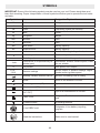
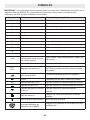
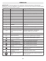
SYMBOLS
IMPORTANT: Some of the following symbols may be used on your tool. Please study them and
learn their meaning. Proper interpretation of these symbols will allow you to operate the tool better
and safer.
Symbol Name Designation/Explanation
V Volts Voltage
A Amperes Current
Hz Hertz Frequency (cycles per second)
W Watt Power
kg Kilograms Weight
min Minutes Time
s Seconds Time
Wh Watt-hours Battery capacity
Ah Ampere-hours Battery capacity
ø Diameter Size of drill bits, grinding wheels, etc.
n0No load speed Rotational speed, at no load
n Rated speed Maximum attainable speed
…/min Revolutions or reciprocations per
minute (rpm)
Revolutions, strokes, surface speed, orbits,
etc. per minute
O Off position Zero speed, zero torque...
1,2,3,…
Ⅰ,Ⅱ,Ⅲ, Selector settings Speed, torque, or position settings. Higher
number means greater speed
Innitely variable selector with off Speed is increasing from 0 setting
Arrow Action in the direction of arrow
Alternating current (AC) Type or a characteristic of current
Direct current (DC) Type or a characteristic of current
Alternating or direct current
(AC / DC) Type or a characteristic of current
Class II tool Designates Double Insulated Construction
tools.
Protective earth Grounding terminal
Li-ion RBRC seal Designates Li-ion battery recycling
program
Read the instructions Alerts user to read manual

-7-
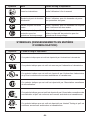
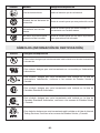
Symbol Name Designation/Explanation
Wear eye protection symbol Alerts user to wear eye protection
Always operate with two hands Alerts user to always operate with two
hands
Do not use the guard for cut-off
operations Do not use the guard for cut-off operations
SYMBOLS (CERTIFICATION INFORMATION)
Symbol Designation/Explanation
This symbol designates that this tool is listed by Underwriters Laboratories.
This symbol designates that this component is recognized by Underwriters
Laboratories.
This symbol designates that this tool is listed by Underwriters Laboratories, to
United States and Canadian Standards.
This symbol designates that this tool is listed by the Canadian Standards
Association.
This symbol designates that this tool is listed by the Canadian Standards
Association, to United States and Canadian Standards.
This symbol designates that this tool is listed by the Intertek Testing Services,
to United States and Canadian Standards.

-8-
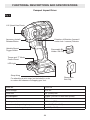
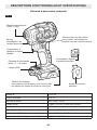
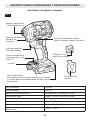
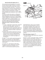
FUNCTIONAL DESCRIPTIONS AND SPECIFICATIONS
Compact Impact Driver
Fig. 1
1/4" (6mm) Hex Chuck
Accessory Install /
Release Button
Variable-Speed
Trigger Switch Removable Bit
Holder / Bit Clip
Removable
Belt Clip
Direction-of-Rotation (forward /
center-lock / reverse) Selector
Strap xing
For attaching a wrist strap (not included) in order
to reduce the chances of dropping your tool.
Torque and “T” Mode
Control Panel
LED Light
Model No. FX1371A
Rated voltage 24 V d.c.
Collet size 1/4'' (6 mm) hex
No-load speed 0-1900 / 0-2700 / 0-4000 /min (RPM)
Maximum torque 2500 in.lbs
Max. impact rate 4450 /min (IPM)
Recommended operating temperature -4-104°F (-20-40℃)
Recommended storage temperature < 122℉ (< 50℃)

-9-
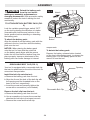
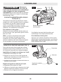
ASSEMBLY
WARNING Detach the battery pack
from the tool before
making any assembly, adjustments or
changing accessories. Such preventive safety
measures reduce the risk of starting the tool
accidentally.
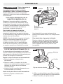
TO ATTACH/DETACH BATTERY PACK (FIG.
2)
Lock the variable-speed trigger switch “OFF”
on the tool by placing the direction-of-rotation
(forward/center-lock/reverse) selector in the
center position before attaching or detaching
the battery pack.
To attach the battery pack:
Align the raised rib on the battery pack with the
grooves in the tool, and then slide the battery
pack onto the tool.
NOTICE: When placing the battery pack
onto the tool, be sure that the raised rib
on the battery pack aligns with the groove
inside the tool and that the latches snap into
place properly. Improper attachment of the
battery pack can cause damage to internal
components.
To detach the battery pack:
Depress the battery-release button located
on the front of the battery pack, to release the
battery pack. Pull the battery pack out and
remove it from the tool.
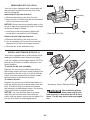
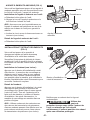
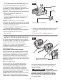
REMOVABLE BELT CLIP (FIG. 3)
Your tool is equipped with a removable belt clip
that can be positioned on the side of the tool for
convenient transportation.
Install the belt clip onto the tool:
a. Remove the battery pack from the tool.
b. Align the rib and the hole of the belt clip with
the opening and the threaded hole on the
base of the tool, respectively.
c. Insert the screw and securely tighten the
screw with a screwdriver (not included).
Remove the belt clip from the tool:
a. Remove the battery pack from the tool.
b. Use a screwdriver to loosen the screw that
attaches the belt clip to the impact wrench.
c. Remove the screw and the belt clip.
Fig. 2
Battery-release
Button
Attach
Detach
Fig. 3
Opening
Rib
Removable Belt Clip

-10-
REMOVABLE BIT CLIP (FIG.4)
Your tool is also equipped with a removable bit
clip that can be positioned on the side of the
tool for storing bits.
Install the bit clip onto the tool:
a. Remove the battery pack from the tool.
b. Align the hole of the bit clip with the threaded
hole on the base of the tool.
NOTICE: Ensure that the protruding part on the
bit clip is kept ush against the step on the base
of the tool to keep it steady.
c. Insert the screw and securely tighten the
screw with a screwdriver (not included).
Remove the bit clip from the tool:
a. Remove the battery pack from the tool.
b. Use a screwdriver to loosen the screw that
attaches the bit clip to the impact wrench.
c. Remove the screw and the bit clip.
INSTALL AND REMOVE BITS (FIG. 5)
Your tool is equipped with a quick-change chuck,
making bit installation and removal very easy.
Lock the variable-speed trigger switch “OFF” by
placing the direction-of-rotation selector in the
center position.
To install the bit (not included):
Depress the accessory install/release button;
the locking sleeve will move forward (away from
the tool)Insert the bit as far as it will go into the
chuck, and then release the accessory install/
release button to lock the bit in place.
To remove the bit:
Depress the accessory install/release button to
push the locking sleeve forward (away from the
tool). Pull the bit from the chuck and release
the accessory install/release button, the locking
sleeve will retract to original position.
NOTICE: Use only bits with power grooves;
other bits can be used with a universal bit
holder that has power groove (not included). Do
not use a bit that has a damaged shank.
WARNING Use protective gloves
when removing the bit
from the tool, or rst allow the bit to cool
down. The bit may be hot after prolonged
use.
Fig. 4
Step
Protuding
Part
Removable Bit Clip
Fig. 5
Accessory Install / Release Button

-11-
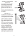
ADJUSTMENTS
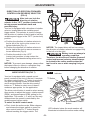
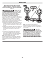
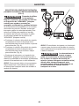
DIRECTION-OF-ROTATION (FORWARD/
CENTER-LOCK/REVERSE) SELECTOR
(FIG. 6)
WARNING After tool use, lock the
direction-of-rotation
selector in the “OFF” position (center-lock)
to help prevent accidental starts and
possible injury.
Your tool is equipped with a direction-of-rotation
selector, located above the variable-speed
trigger switch. This selector is used to change
the direction of rotation of the bit and to lock the
variable-speed trigger in the “OFF” (center-lock)
position.
a. Position the direction-of-rotation selector to
the far left of the tool to drive screws in or
tighten bolts/nuts (Fig. 6).
b. Position the direction-of-rotation selector to
the far right of the tool to remove screws or
loosen bolts/nuts (Fig. 6).
c. Position the switch in the “OFF”
(center-lock) position to help reduce the
possibility of accidental starting when not in
use.
NOTICE: To prevent gear damage, always allow
the impact driver to come to a complete stop
before changing the direction of rotation.
NOTICE: The impact driver will not run unless
the direction-of-rotation selector is engaged fully
to the left or to the right.
WARNING Battery tools are always in
operating condition.
Therefore, the direction-of-rotation (forward/
center-lock/reverse) selector should always
be locked in the center position when the
tool is not in use or when carrying it at your
side.
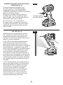
MODE SELECTION (FIG. 7)
Your tool is equipped with a speed-control
panel, located on the foot of the tool. It consists
of a drive-control button, “T” button (a mode for
use with self-tapping screws in sheet metal),
and 5 working modes. Use the drive-control
button or “T” button to select one of these 5
modes as appropriate for the application.
The drive-control button is used to select among
three modes to adjust the torque, rotation-speed
(RPM), and impact-speed (IPM) setting for an
application. The modes 1, 2, and 3 are the only
modes where the speed is controlled by the
variable-speed trigger switch.
To select the drive control mode:
a. First, check the active mode. Either depress
and release the trigger switch or press the
drive control button or “T” button directly
without touching the trigger switch. The
LED indicator below the mode number will
illuminate to indicate the active mode setting.
Fig. 6
Fig. 7 Indicator
"T" Button
Drive Control
Button

-12-
b. Press the drive-control button briey (less
than 0.5 second) to cycle through the 3
modes. Each press changes one torque level.
See more details in the chart below.
“T” is a special mode for fastening self-tapping
screws into sheet metal. Use only the specied
type of screw and material listed in the chart
below.
T1 and T2 modes help to prevent stripping
the screw head, snapping the screw off, or
damage to work surfaces. In T1 mode, the tool
will stop driving automatically once the screw
head is perfectly ush with the work surface. In
T2 mode, the tool will slow the rotation speed
automatically when the screw head is close to
the working surface, so that you can carefully
drive the screw to nal depth, and stop it in time.
To select the “T” mode:
a. Two methods are available to check the
current T mode:
Either depress and release the trigger switch or
press the drive-control button or the “T” button
directly without touching the trigger switch.
The LED indicator below the mode number will
illuminate to indicate the current mode setting.
Press the “T” button briey (less than 0.5
seconds) to cycle between T1 and T2 modes.
Each press changes one mode. See more
details in chart below:
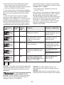
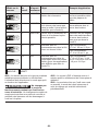
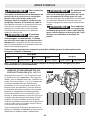
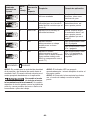
Lit indicator
displayed on
panel
Woking
mode
Maximum
impact
rate Purpose Example of application
11300 IPM Tightening when a good
nishing is needed Tightening screws into
sensitive boards, such as
plaster boards
2 3600 IPM Tightening with less force
and speed than mode 3
(easier to control than
mode 3)
Driving screws into hard
materials as well as
tightening bolts
3 4450 IPM Tightening with the maximum
force and speed
Driving long screws into
hard materials, as well
as tightening bigger bolts
than mode 2
TI N/A Driving self-tapping screws
into sheet metal with good
nish
Recommended type:
#8 x 1/2"
Recommended type:
#10 x 1"
T2 N/A Driving self-tapping screw
into thick metal with good
nish (handing tougher work
compare to T1 mode
Recommended type:
#10 x 1-1/2" or
1/4'' x 2-1/2“
ON ; OFF
NOTICE: The variety of wood density and metal
material may affect the nal outcome. The user
should select appropriate mode based on the
application.
WARNING Do not change the working
mode while the tool is
running. Sudden change of torque may cause
the loss of control causing possible injury or
damage to the tool or workpiece.
NOTICE: The LED indicator will turn off
approximately 1min after the trigger switch is
released.
NOTICE: When the tool is next turned on, the
working mode will revert to the previous setting.

-13-
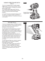
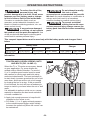
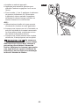
VARIABLE-SPEED TRIGGER SWITCH
(FIG. 8)
Your tool is equipped with a variable-speed
trigger switch. The tool can be turned “ON” or
“OFF” by depressing or releasing the variable-
speed trigger switch.
The variable-speed trigger switch delivers
higher speed with increased trigger pressure
and lower speed with decreased trigger
pressure.
In T1 and T2 modes pressing the trigger switch
will deliver the highest rotation speed within
current mode regardless of the pressure exerted
on the switch.
LED LIGHT (FIG. 9)
Your tool is equipped with an LED light, located
on the base of the tool. This provides additional
light on the surface of the work piece for
operation in lower-light areas.
The LED light will automatically turn on with a
slight squeeze on the variable-speed trigger
switch before the tool starts running and will turn
off approximately 10 seconds after the variable-
speed trigger switch is released.
The LED light will rapidly ash when the tool
and/or battery pack becomes overloaded or too
hot, and the internal sensors will turn the tool
off. Rest the tool for a while or place the tool
and battery pack separately under air ow to
cool them.
The LED light will ash more slowly to indicate
that the battery is at low-battery capacity.
Recharge the battery pack.
If the LED fails to light up when you switch on
the tool, or it turns off suddenly during your
operation, it may be caused by the internal
communication error. Please contact customer
service or an authorized service center for
assistance.
Fig. 9
Fig. 8
Variable-Speed
Trigger Switch

-14-
OPERATING INSTRUCTIONS
WARNING To reduce the risk of re,
personal injury, and
product damage due to a short circuit, never
immerse your tool, battery pack or charger
in uid or allow a uid to ow inside them.
Corrosive or conductive uids, such as
seawater, certain industrial chemicals, and
bleach or bleach-containing products, etc. can
cause a short circuit.
WARNING If any parts are damaged
or missing, do not operate
this product until the parts are replaced. Use
of this product with damaged or missing parts
could result in serious personal injury.
WARNING Do not attempt to modify
this tool or create
accessories not recommended for use with
this tool. Any such alteration or modication is
misuse and could result in a hazardous
condition leading to possible serious injury.
WARNING To prevent accidental
starting that could cause
serious personal injury, always remove the
battery pack from the tool when assembling
parts.
This compact impact driver must be used only with the battery packs and chargers listed
below:
Battery Pack Charger
2.5Ah 5Ah 8Ah 12Ah
FLEX FX0111 FLEX FX0121 FLEX FX0221 FLEX FX0231 FLEX FX0411 FLEX FX0421
NOTICE: Please refer to the battery pack and charger manuals for detailed operating
information.
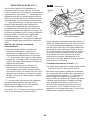
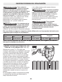
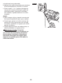
TIGHTEN AND LOOSEN SCREWS, NUTS
AND BOLTS (FIG. 10 AND 11)
Select the T1 or T2 mode as necessary, based
on your application. For more details see
related section: Mode Selection. For mode 1,
2, or 3: variable-speed control must be used
with caution for driving nuts and bolts using
socket-set attachments. The best technique is
to start slowly, increase speed as the nut or bolt
runs down, and then set the nut or bolt snugly
by slowing the tool to a stop. If this procedure
is not followed, the tool will have a tendency to
torque or twist in your hand when the nut or bolt
seats.
It is advisable to perform a trial run on a scrap
material to determine the best mode selection.
a. Install a suitable bit.
b. Apply just enough pressure to keep the bit
engaged on the screw or nut.
c. For mode 1, 2, or 3, apply minimal pressure
to the variable-speed trigger switch initially.
Increase the speed only when full control can
be maintained.
Fig. 10

-15-
NOTICE:
a. Always use the correct type and size of bit for
your application.
b. When turning in a screw at/near the crosscut
end or an edge of wood, pre-drill a hole in
order to avoid cracking of the wood.
c. When screw driving in hard wood, one should
pre-drill a pilot hole.
WARNING Do not over-tighten, as the
force of the impact driver
can break the fastener. Keep the impact
driver at a right angle to the fastener to
avoid damaging the fastener head.
Fig. 11

-16-
MAINTENANCE
WARNING To avoid serious personal
injury, always remove the
battery pack from the tool when cleaning or
performing any maintenance.
SERVICE
WARNING Preventive maintenance
performed by
unauthorized personnel may result in
misplacing of internal wires and
components which could cause a serious
hazard. We recommend that all tool service be
performed by a FLEX Factory Service Center or
Authorized FLEX Service Station.
GENERAL MAINTENANCE
WARNING When servicing, use only
identical replacement
parts. Use of any other parts could create a
hazard or cause product damage. Periodically
inspect the entire product for damaged, missing,
or loose parts such as screws, nuts, bolts, caps,
etc. Tighten securely all fasteners and caps and
do not operate this product until all missing or
damaged parts are replaced. Please contact
customer service or an authorized service
center for assistance.
CLEANING
The tool may be cleaned most effectively
with compressed dry air. Always wear
safety goggles when cleaning tools with
compressed air. Ventilation openings and
switch levers must be kept clean and free of
foreign matter. Do not attempt to clean by
inserting pointed objects through openings.
WARNING Certain cleaning agents
and solvents damage
plastic parts. Some of these are: gasoline,
carbon tetrachloride, chlorinated cleaning
solvents, ammonia and household detergents
that contain ammonia.
STORAGE
Store the tool indoors in a place that is
inaccessible to children. Keep away from
corrosive agents.
ACCESSORIES
WARNING The use of any other accessories not specied in this manual may create a
hazard.
Removable Belt Clip
Removable Bit Holder / Bit Clip

-17-
FLEX 5 YEAR LIMITED WARRANTY
Chervon North America, Inc. ("Seller") warrants to the original purchaser only, that all FLEX 24V
products will be free from defects in material or workmanship for a period of ve years from date of
purchase when the original purchaser registers the product within 30 days from the date of original
retail purchase and retains their receipt as proof of purchase. THE 5-YEAR LIMITED WARRANTY
PERIOD IS CONDITIONED ON REGISTRATION OF THE PRODUCT WITHIN 30 DAYS OF
PURCHASE AND ONLY APPLICABLE TO FLEX 24V TOOLS, BATTERIES AND CHARGERS. If the
original purchaser does not register their product within 30 days, the foregoing limited warranty will
apply for a duration of three years. Product registration can be completed online at
www.registermyex.com.
24V Tools: 5-Year Limited Warranty with Registration
24V Batteries and Chargers: 5-Year Limited Warranty with Registration
Corded, 12V and 20V FLEX Legacy Products: 1-Year Limited Warranty, No Registration Benet
Accessories and Attachments: No Warranty
SELLER’S SOLE OBLIGATION AND YOUR EXCLUSIVE REMEDY under this 5-Year Limited
Warranty and, to the extent permitted by law, any warranty or condition implied by law, shall be
the repair or replacement of parts, without charge, which are defective in material or workmanship
and which have not been misused, carelessly handled, or repaired by persons other than a FLEX
Authorized Service Dealer. This warranty does not cover part failure due to normal wear and tear.
To make a claim under warranty, return the complete product, transportation prepaid, to any FLEX
Authorized Service Dealer. For Authorized FLEX Service Dealers, please visit www.registermyex.com
or call 1-833-FLEX-496 (1-833-353-9496).
This 5-Year Limited Warranty does not apply to accessories, attachments or parts.
Any implied warranties applicable to a product shall be limited in duration equal to the duration of the
express warranties applicable to such product, as set forth in the rst paragraph above. Some states
in the U.S. and some Canadian provinces do not allow limitations on how long an implied warranty
lasts, so the above limitation may not apply.
FLEX is not responsible for direct, indirect, incidental or consequential damages. Some U.S. states
and Canadian provinces do not allow limitations on how long an implied warranty lasts and/or do
not allow the exclusion or limitation of incidental or consequential damages, so the above limitations
or exclusions may not apply. This limited warranty gives you specic legal rights, and you may also
have other rights which vary by state in the U.S. and by province in Canada.
This limited warranty applies only to products sold within the United States of America, Canada and
the commonwealth of Puerto Rico. For warranty coverage within other countries, contact your local
FLEX dealer.
© Chervon North America, 1203 E. Warrenville Rd., Naperville, IL 60563
www.expowertools.com
www.registermyex.com
1-833-FLEX-496 (1-833-353-9496)

-18-
SYMBOLES RELATIFS À LA SÉCURITÉ
La raison d’être des symboles relatifs à la sécurité est d’attirer votre attention sur des dangers
possibles. Il est important de vous familiariser avec les symboles relatifs à la sécurité et les
explications qui les accompagnent an de bien les comprendre. Les avertissements et les symboles
associés ne sufsent pas à éliminer tous les dangers. Les instructions et les avertissements qu’ils
donnent ne sauraient remplacer des mesures de prévention des accidents appropriées.
AVERTISSEMENT Lisez toutes les consignes de sécurité qui sont contenue dans ce
Mode d’emploi, y compris tous les symboles d’alerte relatifs à la
sécurité tels que « DANGER », « AVERTISSEMENT » et « MISE EN GARDE », et assurez-vous
que vous les comprenez bien avant de commencer à utiliser cet outil. La non-observation de toutes
les instructions gurant ci-après pourrait causer un choc électrique, un incendie et/ou des blessures
personnelles graves.
Les dénitions ci-dessous décrivent le niveau de gravité pour chaque terme signalant un danger.
Veuillez lire le mode d’emploi et lire la signication de ces symboles.
C’est le symbole d’alerte relatif à la sécurité. Il est utilisé pour vous
avertir de l’existence possible d’un danger de lésion corporelle.
Obéissez à tous les messages relatifs à la sécurité qui suivent ce
symbole pour éviter tout risque de blessure ou même de mort.
DANGER DANGER indique une situation dangereuse qui, si elle n’est pas
évitée, causera la mort d’une personne ou une blessure grave.
AVERTISSEMENT AVERTISSEMENT indique une situation dangereuse qui, si elle
n’est pas évitée, causera la mort d’une personne ou une blessure
grave.
MISE EN GARDE MISE EN GARDE, conjointement avec le symbole d’alerte en
liaison avec la sécurité, indique une situation dangereuse qui, si
elle n'est pas évitée, causera une blessure légère ou modérée.
Messages d’information et de prévention des dommages
Ils informent l’utilisateur d’informations et/ou d’instructions importantes qui pourraient entraîner des
dommages matériels ou aux équipements s’ils ne sont pas suivis. Chaque message est précédé par
le terme « AVIS », comme dans l’exemple ci-dessous :
AVIS : Un dommage matériel et/ou aux équipements peut survenir si ces instructions ne sont pas
suivies.
AVERTISSEMENT Pendant leur fonctionnement, les outils
électriques peuvent projeter des corps
étrangers dans les yeux de leur utilisateur et lui iniger de graves blessures
aux yeux. Portez toujours des lunettes de protection ou des lunettes de
sécurité à écrans latéraux et un masque couvrant tout le visage lors de
l’utilisation de ce produit. Nous recommandons de porter un masque de
sécurité à vision latérale large au-dessus des lunettes ordinaires ou des
lunettes de sécurité standard avec des écrans de protection sur les côtés.
Utilisez toujours un équipement de protection des yeux indiquant qu’il est
conforme à la norme ANSI Z87.1.

-19-
AVERTISSEMENTS GÉNÉRAUX RELATIFS À LA SÉCURITÉ POUR
LES OUTILS ÉLECTRIQUES
AVERTISSEMENT Lisez tous les avertissements relatifs à la sécurité, les
instructions, les illustrations et les spécications fournies avec
cet outil électrique. Le non-respect de toutes les instructions gurant ci-après pourrait causer un
choc électrique, un incendie et/ou des blessures graves.
CONSERVEZ TOUS LES AVERTISSEMENTS ET TOUTES LES INSTRUCTIONS
POUR RÉFÉRENCE FUTURE.
Le terme « outil électrique » dans les avertissements fait référence à votre outil électrique à cordon
électrique branché dans une prise secteur ou à votre outil électrique à piles (sans l).
Sécurité de la zone de travail
Gardez votre zone de travail propre et bien
éclairée. Des zones encombrées ou sombres
sont propices aux accidents.
N’utilisez pas des outils électriques dans
une atmosphère explosive, par exemple
en présence de liquides, de gaz ou de
poussières inammables. Les outils
électriques produisent des étincelles qui
risquent de mettre feu aux poussières ou aux
émanations de fumée.
Gardez les enfants et autres personnes
présentes à une distance sufsante lorsque
vous utilisez un outil électrique. Des
distractions risqueraient de vous faire perdre le
contrôle.
Sécurité électrique
La che de l’outil électrique doit
correspondre à la prise de courant. Ne
modiez jamais une che de quelque façon
que ce soit. N’utilisez pas d’adaptateurs
de ches avec des outils électriques mis
à la terre/à la masse. L’emploi de ches non
modiées et de prises de courant correspondant
naturellement aux ches réduira le risque de
choc électrique.
Évitez tout contact de votre corps avec des
surfaces mises à la terre ou à la masse telles
que des surfaces de tuyaux, de radiateurs,
de cuisinières et de réfrigérateurs. Il existe un
risque accru de choc électrique si votre corps
est en contact avec la terre ou la masse.
N’exposez pas d’outils électriques à la
pluie ou à un environnement humide. La
pénétration d’eau dans un outil électrique
augmentera le risque de choc électrique.
N’utilisez pas le cordon de façon abusive.
N’utilisez pas le cordon pour porter, tirer
ou débrancher l’outil électrique. Tenez
le cordon à distance de toute source de
chaleur, d’huile, de bords tranchants ou de
pièces mobiles. Des cordons endommagés
ou entortillés augmentent le risque de choc
électrique.
Lorsque vous utilisez un outil électrique à
l’extérieur, employez un cordon de rallonge
approprié pour un emploi à l’extérieur.
L’utilisation d’un cordon approprié pour une
utilisation à l’extérieur réduit le risque de choc
électrique.
S’il est inévitable d’utiliser un outil
électrique dans un environnement humide,
utilisez une alimentation protégée par un
disjoncteur de circuit de fuite à la terre.
L’utilisation d’un tel circuit réduit le risque de
choc électrique.
Sécurité personnelle
Faites preuve de vigilance et de bon sens, et
observez attentivement ce que vous faites
lorsque vous utilisez un outil électrique.
N’utilisez pas un outil électrique si vous êtes
fatigué(e) ou sous l’inuence de drogues,
d’alcool ou de médicaments. Un simple
moment d’inattention pendant que vous utilisez
un outil électrique pourrait causer une blessure
grave.
Utilisez des équipements de protection
personnelle. Portez toujours des
équipements de protection des yeux.
Des équipements de protection tels qu’un
masque de protection contre la poussière, des
chaussures de sécurité antidérapantes, un
casque ou un dispositif de protection de l’ouïe
utilisés en fonction des conditions réduiront le
nombre des blessures.

-20-
Prévenez une mise en marche accidentelle.
Assurez-vous que l’interrupteur est dans la
position d’arrêt (OFF) avant de connecter
l’appareil à une source d’alimentation et/
ou à un bloc-piles, de le soulever ou de le
transporter. Le fait de transporter des outils
électriques avec le doigt sur l’interrupteur ou de
mettre sous tension des outils électriques avec
l’interrupteur en position de marche invite les
accidents.
Retirez toute clé de réglage pouvant être
attachée à l’outil avant de mettre l’outil
électrique sous tension. Une clé laissée
attachée à une pièce en rotation de l’outil
électrique pourrait causer une blessure.
Ne faites rien qui risquerait de vous faire
perdre l’équilibre. Veillez à toujours garder
un bon équilibre et un appui stable. Ceci
permet de mieux contrôler l’outil électrique dans
des situations inattendues.
Portez des vêtements appropriés. Ne portez
pas de bijoux ou de vêtements amples.
Gardez vos cheveux et vos vêtements à une
distance sufsante des pièces mobiles. Les
vêtements amples, bijoux ou cheveux longs
pourraient être attrapés par des pièces mobiles.
Si des dispositifs sont fournis pour le
raccordement d’accessoires d’extraction et
de collecte de la poussière, assurez-vous
qu’ils sont connectés et utilisés de façon
appropriée. L’emploi correct de l’accessoire
de collecte de la poussière peut réduire les
dangers associés à la poussière.
Ne laissez pas la familiarité résultant de
l’utilisation fréquente des outils vous inciter
à devenir complaisant(e) et à ignorer les
principes de sécurité des outils. Une action
négligente pourrait causer des blessures graves
en une fraction de seconde.
Utilisation et entretien de l’outil
électrique
N’imposez pas de contraintes excessives
à l’outil électrique. Utilisez l’outil électrique
approprié pour votre application. L’outil
électrique correct fera le travail plus
efcacement et avec plus de sécurité à
la vitesse à laquelle il a été conçu pour
fonctionner.
N’utilisez pas l’outil électrique si
l’interrupteur de marche/arrêt ne permet pas
de le mettre sous tension/hors tension. Tout
outil électrique qui ne peut pas être contrôlé
par son interrupteur est dangereux et doit être
réparé.
Débranchez la che de la prise secteur et/
ou retirez le bloc-piles de l’outil électrique
(s’il est amovible) avant d’y apporter de
quelconques modications, de changer
d’accessoire ou de ranger l’outil électrique.
De telles mesures de sécurité préventives
réduisent le risque de déclenchement accidentel
de l’outil électrique.
Rangez les outils électriques qui ne sont
pas utilisés activement hors de portée des
enfants, et ne laissez aucune personne
n’ayant pas lu ces instructions et ne sachant
pas comment utiliser un tel outil se servir de
cet outil. Les outils électriques sont dangereux
quand ils sont entre les mains d’utilisateurs
n’ayant pas reçu la formation nécessaire à leur
utilisation.
Entretenez de façon appropriée les outils
électriques et les accessoires.
Assurez-vous que les pièces en mouvement
sont bien alignées et qu’elles ne se
coincent pas, qu’il n’y a pas de pièces
cassées ou qu’il n’existe aucune situation
pouvant affecter le fonctionnement de
l’outil électrique. Si l’outil électrique est
endommagé, faites-le réparer avant de vous
en servir à nouveau. De nombreux accidents
sont causés par des outils électriques mal
entretenus.
Gardez les outils de coupe tranchants et
propres. Des outils de coupe entretenus de
façon adéquate avec des bords de coupe
tranchants sont moins susceptibles de se
coincer et sont plus faciles à contrôler.
Utilisez l’outil électrique, les accessoires,
les mèches de perçage, etc. conformément
à ces instructions, en tenant compte
des conditions de travail et de la tâche à
accomplir. L’utilisation de l’outil électrique
pour des opérations différentes de celles pour
lesquelles il est conçu pourrait causer une
situation dangereuse.
Gardez les poignées et les surfaces de
préhension propres, sèches et exemptes
de toute trace d’huile ou de graisse. Les
poignées et les surfaces de préhension
glissantes ne permettent pas une manipulation
et un contrôle sûrs de l’outil dans des situations
inattendues.
La page est en cours de chargement...
La page est en cours de chargement...
La page est en cours de chargement...
La page est en cours de chargement...
La page est en cours de chargement...
La page est en cours de chargement...
La page est en cours de chargement...
La page est en cours de chargement...
La page est en cours de chargement...
La page est en cours de chargement...
La page est en cours de chargement...
La page est en cours de chargement...
La page est en cours de chargement...
La page est en cours de chargement...
La page est en cours de chargement...
La page est en cours de chargement...
La page est en cours de chargement...
La page est en cours de chargement...
La page est en cours de chargement...
La page est en cours de chargement...
La page est en cours de chargement...
La page est en cours de chargement...
La page est en cours de chargement...
La page est en cours de chargement...
La page est en cours de chargement...
La page est en cours de chargement...
La page est en cours de chargement...
La page est en cours de chargement...
La page est en cours de chargement...
La page est en cours de chargement...
La page est en cours de chargement...
La page est en cours de chargement...
La page est en cours de chargement...
La page est en cours de chargement...
La page est en cours de chargement...
La page est en cours de chargement...
-
 1
1
-
 2
2
-
 3
3
-
 4
4
-
 5
5
-
 6
6
-
 7
7
-
 8
8
-
 9
9
-
 10
10
-
 11
11
-
 12
12
-
 13
13
-
 14
14
-
 15
15
-
 16
16
-
 17
17
-
 18
18
-
 19
19
-
 20
20
-
 21
21
-
 22
22
-
 23
23
-
 24
24
-
 25
25
-
 26
26
-
 27
27
-
 28
28
-
 29
29
-
 30
30
-
 31
31
-
 32
32
-
 33
33
-
 34
34
-
 35
35
-
 36
36
-
 37
37
-
 38
38
-
 39
39
-
 40
40
-
 41
41
-
 42
42
-
 43
43
-
 44
44
-
 45
45
-
 46
46
-
 47
47
-
 48
48
-
 49
49
-
 50
50
-
 51
51
-
 52
52
-
 53
53
-
 54
54
-
 55
55
-
 56
56


Flex FX1371A 24V BRUSHLESS IMPACT DRIVER Manuel utilisateur
- Catégorie
- Clés à chocs électriques
- Taper
- Manuel utilisateur