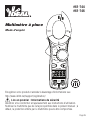
Ideal 600A AC Clamp-Pro™ Clamp Meter Mode d'emploi
- Catégorie
- Mesure, test
- Taper
- Mode d'emploi

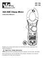
#61-744
#61-746
600 AAC Clamp Meter
Instruction Manual
OFF
K
HOLD
NCV
AC
DC
VΩmMA
APO
600
Ω
40
A
V
V
CLAMP
CAT. III
600V
600A
NCV
OFF
V
Ω
V
True RMS
40
A
600
AM
HOLD
DC
K
AC
mΩV
APO
CAT. III
600V
600A
CLAMP
61-744
61-746
CAT.III
600V
V/Ω
COM
CAT.III
600V
V/Ω
COM
Page 1
Register your product and access more information at http://www.idlim.net/
support/registration/
Read First: Safety Information
Understand and follow operating instructions carefully. Use the meter, test leads
and all accessories only as specified in this manual; otherwise, the protection
provided by the meter can be impaired.

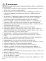
WARNING
To avoid possible electric shock, personal injury or death, follow these
guidelines:
• Do not use if meter appears damaged. Visually inspect the meter to ensure case
and jaws are not cracked.
• Inspect and replace test leads if insulation is damaged, metal is exposed, or
probes are cracked. Pay particular attention to the insulation surrounding the
connectors.
•
To preserve the safety rating of this product, use only test leads with a minimum
rating of CAT III 600V. Do not use improvised connections that could present a safety
hazard.
• Note that the measurement category and voltage rating of combinations of
the meter, the test leads, and the accessories is the lowest of the individual
components.
• Do not use meter if it operates abnormally as protection may be impaired.
• Do not use during electrical storms or in wet weather.
• Do not use around explosive gas, dust, vapor or in damp or wet environments.
Do not submerge or expose the meter to water and do not use if the meter has
ever been exposed to water or other fluids.
• Do not apply more than the rated voltage or amperage.
• Remove the test leads from the input jacks before measuring current.
• Replace battery as soon as battery indicator appears to avoid false readings.
• Remove the test leads from the meter prior to removing battery cover.
• Do not use without the battery and battery cover properly installed.
• Do not attempt to repair this unit as it has no user-serviceable parts.
• Use the proper terminals, functions and range for your measurements.
• Never ground yourself when taking electrical measurements.
• Connect the black common lead to ground or neutral before applying the red test
lead to potential voltage. Disconnect the red test lead from the voltage first.
• Keep fingers behind the guard rings of the probe tips.
• Hold the clamp behind the tactile barrier.
• Voltages exceeding 30VAC or 60VDC pose a shock hazard so use caution.
• Remove batteries before storage or if unit will not be used for longer than 1
month.
Page 2

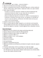
CAUTION
To protect yourself, think “Safety First”:
• Comply with local and national safety codes.
• Use appropriate personal protective equipment such as face shields, insulating
gloves, insulating boots, and/or insulating mats.
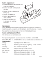
• Before each use:
- Perform a continuity test by touching the metal tips of the test leads
together to verify the functionality of the battery and test leads.
- Use the 3 Point Safety Method. (1) Verify meter operation by measuring a
known voltage. (2) Apply meter to circuit under test. (3) Return to the
known live voltage again to ensure proper operation.
• Always work with a partner.
• Remove the batteries for storage or if the meter will not be used for longer than
one month. Battery leakage will compromise the safety of the meter and cause
damage to internal components.
Features:
• Auto/manual ranging clamp meter
• Non-Contact Voltage (70-600VAC)
• Measures 600 AAC Current
• Measures AC/DC Voltage and Resistance
• Audible continuity
• Data hold
• Auto Power Off
• Low Battery Indicator
• Compact jaws for reaching into tight spaces
• Electronic overload protection on all ranges
• 61-744 model is averaging sensing, rms calibrated
• 61-746 model is true rms sensing.
Page 3

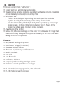
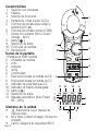
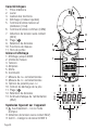
Features
1. Jaw Clamp
2. Lever
3. Function Dial
4. Display (LCD)
5. Volts and resistance (V-Ω)
input terminal
6. Common (COM) input terminal
7. Non-Contact Voltage (NCV)
8. Range ( )
9. Data Hold
10. Measuring Functions
11. Tactile Barrier
Display Icons
1. 4000 count display
2. Units of measure
3. Voltage
4. Amperes
5. Ohms
6. Continuity
7. AC measurement is selected
8. DC measurement is selected
9. Polarity indicator for DC
10. Low battery indicator
11. Range ( )
12. Data hold
13. APO - Auto Power Off
Symbols on the Unit
• Warning - read the instruction manual
• NCV - Non-Contact Voltage
• Cat III - 600V Safety category
1
6
4
23
5
OFF
K
HOLD
NCV
AC
DC
VΩmMA
APO
600
Ω
40
A
V
V
CLAMP
CAT. III
600V
600A
NCV
OFF
V
Ω
V
True RMS
40
A
600
AM
HOLD
DC
K
AC
mΩV
APO
CAT. III
600V
600A
CLAMP
61-744
61-746
CAT.III
600V
V/Ω
COM
CAT.III
600V
V/Ω
COM
1
9
11
3
8
4
5
10
6
7
2
10
11 12 13
7
8
9
Page 4
HOLD APO
AC
DC
K M Ω m VA

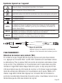
Symbols on the Unit
Risk of Danger. Important Information. See Manual.
Hazardous voltage. Risk of electrical shock.
Application around and removal from Hazardous Live conductors is permitted.
AC (Alternating Current)
DC (Direct Current)
Earth Ground
CAT II Measurement Category II applies to test and measuring circuits connected directly to
utilization points (socket outlets and similar points) of the low-voltage installation
CAT III Measurement Category III applies to measuring circuits connected to the distribution
part of the building’s low-voltage installation
CAT IV Measurement Category IV applies to test and measuring circuits connected at the
source of the building’s low-voltage installation
~
...
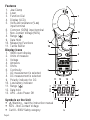
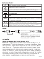
Test Leads
OPERATION:
Non-contact voltage (NCV)
With the NCV tab on the tip of the clamp close to an AC voltage, press the NCV but-
ton. The NCV LED will light and the beeper will sound. The closer the NCV tab is to
AC voltage, the louder the beep. To differentiate between hot and neutral in an outlet,
insert the NCV tab into each slot in the outlet. The beeper will be much louder on the
hot side of the outlet than the neutral. The test lead can also be used to differentiate
between the hot and neutral. Plug the red test lead into the V/Ω input jack on the
meter. Press the NCV button and insert the probe tip into each slot of the outlet. The
beeper will only beep on the hot side of the outlet.
Page 5
Guard ring
CAT IV 600V
CAT III 1000V CAT II 1000V
Always replace the protective Category Caps if removal is
necessary for use in a standard 120 volt outlet.

Symbols on the Unit
Risk of Danger. Important Information. See Manual.
Hazardous voltage. Risk of electrical shock.
Application around and removal from Hazardous Live conductors is permitted.
AC (Alternating Current)
DC (Direct Current)
Earth Ground
CAT II Measurement Category II applies to test and measuring circuits connected directly to
utilization points (socket outlets and similar points) of the low-voltage installation
CAT III Measurement Category III applies to measuring circuits connected to the distribution
part of the building’s low-voltage installation
CAT IV Measurement Category IV applies to test and measuring circuits connected at the
source of the building’s low-voltage installation
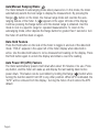
Auto/Manual Ranging Mode ( )
The meter defaults to autoranging mode when powered on. In this mode, the meter
automatically selects the best range to display the measurement. By pressing the
Range ( ) button on the meter, the manual range mode will override the auto-
ranging feature of the meter. A ( ) appears in the upper left side of the display.
Continue pressing the Range button until the desired range is obtained. Use this
mode to lock in a specific range for repeated measurements. To return to the
autoranging mode, either depress the Range button for greater than 1 second or turn
the meter off and then back on again.
Data Hold Feature
Press the Hold button on the side of the meter to toggle in and out of the data hold
mode. “HOLD” appears in the upper left of the meter display when data hold is
active. Use the data hold feature to lock a measurement reading on the display. Press
the Hold button again to unlock the display and obtain a real-time reading.
Auto Power Off (APO) Feature
The meter automatically powers itself down after about 10 minutes of no use. Press
any button, and the meter will wake up and display the last reading taken before
power down. This feature can be overridden by holding the Range ( ) button while
turning the function switch from Off to any other position. When APO is defeated, the
“APO” will be removed from the display. Turning the meter off will restore the APO
default.
Page 6

NCV
OFF
V
Ω
V
True RMS
40
A
600
AM
HOLD
DC
K
AC
mΩV
APO
CAT.III
600V
600A
CLAMP
61-746
CAT.III
600V
V/Ω
COM
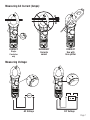
CORRECT
Use with
line splitter
INCORRECT
Currents
cancel
CORRECT
Single
Conductor
only
AC Voltage DC Voltage
NCV
OFF
V
Ω
V
True RMS
40
A
600
AM
HOLD
DC
K
AC
mΩV
APO
CAT.III
600V
600A
CLAMP
61-746
CAT.III
600V
V/Ω
COM
NCV
OFF
V
Ω
V
True RMS
40
A
600
AM
HOLD
DC
K
AC
mΩV
APO
CAT.III
600V
600A
CLAMP
61-746
CAT.III
600V
V/Ω
COM
Measuring AC Current (Amps):
H
N
NCV
OFF
V
Ω
V
True RMS
40
A
600
AM
HOLD
DC
K
AC
mΩV
APO
CAT.III
600V
600A
CLAMP
61-746
CAT.III
600V
V/Ω
COM
CAT.III
600V
V/Ω
COM
NCV
OFF
V
Ω
V
True RMS
40
A
600
AM
HOLD
DC
K
AC
mΩV
APO
CAT.III
600V
600A
CLAMP
61-746
NCV
OFF
V
Ω
V
True RMS
40
A
600
AM
HOLD
DC
K
AC
mΩV
APO
CAT.III
600V
600A
CLAMP
61-746
CAT.III
600V
V/Ω
COM
CAT.III
600V
V/Ω
COM
NCV
OFF
V
Ω
V
True RMS
40
A
600
AM
HOLD
DC
K
AC
mΩV
APO
CAT.III
600V
600A
CLAMP
61-746
NCV
OFF
V
Ω
V
True RMS
40
A
600
AM
HOLD
DC
K
AC
mΩV
APO
CAT. III
600V
600A
CLAMP
61-746
CAT. III
600V
V/Ω
COM
Measuring Voltage:
Page 7

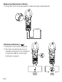
Measuring Resistance (Ohms):
• Verify the circuit is de-energized to obtain accurate measurements.
CAT.III
COMV/Ω
600V
NCV
OFF
V
Ω
V
True RMS
40
A
600
AM
HOLD
DC
K
AC
mΩV
APO
CAT.III
600V
600A
CLAMP
61-746
CAT.III
COMV/Ω
600V
NCV
OFF
V
Ω
V
True RMS
40
A
600
AM
HOLD
DC
K
AC
mΩV
APO
CAT.III
600V
600A
CLAMP
61-746
Closed
Circuit
Open
Circuit
CAT.III
COMV/Ω
600V
NCV
OFF
V
Ω
V
True RMS
40
A
600
AM
HOLD
DC
K
AC
mΩV
APO
CAT.III
600V
600A
CLAMP
61-746
CAT.III
COMV/Ω
600V
NCV
OFF
V
Ω
V
True RMS
40
A
600
AM
HOLD
DC
K
AC
mΩV
APO
CAT.III
600V
600A
CLAMP
61-746
CAT.III
COMV/Ω
600V
NCV
OFF
V
Ω
V
True RMS
40
A
600
AM
HOLD
DC
K
AC
mΩV
APO
CAT.III
600V
600A
CLAMP
61-746
Verifying Continuity ( ):
• Verify the circuit is de-energized.
• The meter will sense the level of
resistance and beep if the resistance
is less than 25Ω to confirm that
continuity is present.
Page 8

+
+
-
-
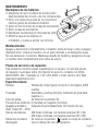
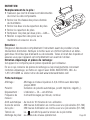
Battery Replacement:
• Ensure test leads are disconnected from
circuit or components.
• Remove test leads from input jacks
on meter.
• Remove the two screws from the
battery cap.
• Remove the battery cap.
• Replace batteries with two
“AAA” batteries.
• Assemble the battery cap
to the meter and re-tighten
the screws.
Maintenance:
Switch off and disconnect the meter completely before carrying out any maintenance.
Clean the case with a damp cloth and mild detergent. Do not use abrasives or solvents.
Keep away from liquids and ensure the meter is completely dry before use.
Service and Replacement Parts:
This unit has no user-serviceable parts.
For replacement parts or to inquire about service information contact IDEAL
INDUSTRIES, INC. at 1-877-201-9005 or visit our website www.idealindustries.com.
Specifications:
Display: 3-3/4 digit LCD with 4000 counts
Polarity: Automatic, positive implied, negative (-) polarity indication.
Overrange: “OL” indication is displayed.
Measure Rate: Samples 2 times per second, nominal.
Auto Power Off: Approximately after 10 minutes of non-use.
Battery Life: 400 hours continuous with Alkaline (61-744)
250 hours continuous with Alkaline (61-746)
Page 9

Low Battery Indication: The “ “ is displayed when battery voltage drops below
operating level.
Power Supply: (2) 1.5V “AAA” batteries (NEDA R03).
Includes an isolated battery compartment.
Accuracy: Stated accuracy at 23°C ±5°C, <75% R.H.
Temperature 0.1 x (specified accuracy) per °C,
Coefficient: (0°C to 18°C, 28°C to 50°C).
Altitude: 6561.7 ft. (2000m)
Operating Environment: 32°F to 122°F (0°C to 50°C) at < 70% R.H.
Storage Environment: -4°F to 140°F (-20°C to 60°C) at < 80% R.H.
Jaw Opening: Accepts a 1.50” (38mm) conductor
Dimensions: 8.0”H x 2.6”W x 1.5”D (203mm H x65mm W x37mm D)
Weight: 7.1 oz. (200g) including batteries
Accessories included: Carrying Case, Test Leads, (2) 1.5V “AAA” batteries,
operating instructions.
Safety: Complies with UL/IEC/EN: 61010-1, 61010-2-032,
61010-031 specifications, Cat III-600V.
Double Insulation
Instrument has been evaluated and complies with insulation category III (overvoltage
category III). Pollution degree 2 in accordance with IEC-644. Indoor use.
Ranges & Accuracies:
AC Converter:
61-744 model is averaging sensing, rms calibrated
61-746 model is true rms sensing.
Accuracy:
Accuracy is specified as +/-(a percentage of the reading + a fixed amount) at
23°C±5°C (73.4°F ± 9°F), less than 75% relative humidity.
N12966
+
Page 10

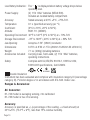
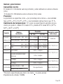
Accuracy
Function Range and Overload
Resolution 61-744 61-746 Protection
AC Current* 40.00A//400.0A/600A (50Hz - 60Hz) 1.7% + 6 digits 1.7% + 10 digits 600AAC
40.00A/400.0A/600A (60Hz - 400Hz) 3.0% + 6 digits 3.0% + 10 digits
AC Voltage 400.0V (50Hz - 500Hz) 1.2% + 5 digits 1.2% + 8 digits 600 VDC or AC rms
600V (50Hz - 500Hz) 1.5% + 5 digits 1.5% + 8 digits
DC Voltage 400.0V/600V 0.5% + 2 digits 600 VDC or AC rms
400.0Ω/4.000kΩ/40.00kΩ/ 1.0% + 4 digits
400.0k Ω
Resistance 4.000MΩ 1.5% + 4 digits 600 VDC or AC rms
40.00MΩ 3.0% + 5 digits
Continuity Audible indication < 25Ω N/A 600 VDC or AC rms
Response time: 500ms
* Accuracy stated for crest factor ≤ 3
Input Impedance is 10MΩ.
Temperature Coefficient: 0.1 times the applicable accuracy specification per
degree C from 0°C to 18°C and 28°C to 50°C (32°F to 64°F and 82°F to 122°F)
Page 11

Warranty Statement:
This tester is warranted to the original purchaser against defects in material and
workmanship for two years from the date of purchase. During this warranty period,
IDEAL INDUSTRIES, INC. will, at its option, replace or repair the defective unit, subject
to verification of the defect or malfunction. Your original receipt from an authorized
distributor of IDEAL INDUSTRIES, INC. is your proof of purchase. Register your product
at: http://www.idlim.net/support/registration/.
This warranty does not apply to defects resulting from abuse, neglect, accident,
unauthorized repair, alteration, or unreasonable use of the instrument.
Any implied warranties arising out of the sale of an IDEAL product, including but not
limited to implied warranties of merchantability and fitness for a particular purpose, are
limited to the above. The manufacturer shall not be liable for loss of use of the
instrument or other incidental or consequential damages, expenses, or economic loss,
or for any claim or claims for such damage, expenses or economic loss.
State laws vary, so the above limitations or exclusions may not apply to you. This
warranty gives you specific legal rights, and you may also have other rights which vary
from state to state.
Page 12

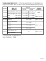
#61-744
#61-746
Medidor de pinza
Manual de Instrucciones
OFF
K
HOLD
NCV
AC
DC
VΩmMA
APO
600
Ω
40
A
V
V
CLAMP
CAT. III
600V
600A
NCV
OFF
V
Ω
V
True RMS
40
A
600
AM
HOLD
DC
K
AC
mΩV
APO
CAT. III
600V
600A
CLAMP
61-744
61-746
CAT.III
600V
V/Ω
COM
CAT.III
600V
V/Ω
COM
Registre su producto y acceda a más información en
http://www.idlim.net/support/
registration/
Lea Primero: Información de Seguridad
Entienda y siga las instrucciones de operación cuidadosamente. Use el multímetro, las
sondas y todos los accesorios únicamente como se especifica en este manual; de lo
contrario, la protección que proporciona el multímetro puede verse perjudicada.
Page 13

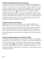
ADVERTENCIA
Para evitar posibles riesgos de descarga eléctrica, lesiones o la muerte, siga estas
directrices:
• No use el multímetro si el mismo parece estar dañado. Inspecciónelo visualmente
para asegurarse de que la cubierta y la pinza no estén quebradas.
• Inspeccione y reemplace los cables si el aislamiento está dañado, hay metal expuesto
o las sondas están quebradas. Preste atención especial al aislante alrededor de los
conectores.
• Para mantener la clasificación de seguridad de este producto, use únicamente
cables de sonda con una clasificación mínima de CAT IV 600V No use conexiones
improvisadas que puedan presentar un riesgo de seguridad.
• Tome nota de que la categoría de medición y la clasificación de voltaje de
combinaciones del multímetro, la sondas y los accesorios es la más baja de los
componentes individuales.
• No utilice el medidor si funciona anormalmente, ya que la protección puede estar
afectada.
• No use el multímetro durante tormentas eléctricas o en clima húmedo.
• No use cerca de gases explosivos, polvo, vapor o en ambientes mojados o húmedos.
No sumerja ni exponga el medidor al agua y no lo use si el medidor ha estado
expuesto alguna vez al agua o a otros líquidos.
• No aplique voltajes superiores a las nominales al multímetro.
• Quite las sondas de los puertos de entrada antes de medir corriente.
• Reemplace la batería tan pronto aparezca el indicador de carga de batería baja, para
evitar las lecturas falsas.
• Retire las sondas del multímetro antes de quitar la tapa de la batería.
• No use el multímetro sin la batería, ni sin la tapa de la batería correctamente instalada.
• No intente reparar esta unidad ya que no tiene piezas reparables por el usuario.
• Use las terminales, funciones y rangos apropiados para sus medidas.
• No se conecte a tierra cuando tome medidas eléctricas.
• Conecte la sonda negra común a tierra o a neutro antes de tocar la sonda roja a
voltaje potencial. Desconecte la sonda roja del voltaje primero.
• Mantenga los dedos detrás de los anillos protectores en las puntas de las sondas.
• Mantenga el producto tras la barrera táctil.
• Los voltajes superiores a 30 VCA o 60 VCD representan un riesgo de descarga
eléctrica, así que tenga precaución.
• Quitar las baterías antes del almacenamiento o si la unidad no va a ser utilizada por
más de 1 mes.
Page 14

PRECAUCIÓN
Para protegerse, piense “¡La seguridad primero!”:
• Cumpla con los requisitos de seguridad locales y nacionales.
• Use equipos de protección personal apropiados, tales como, caretas, guantes aislantes,
calzado y/o alfombras aislantes.
• Antes de cada uso:
- Realice una prueba de continuidad tocando las puntas metálicas de los cables
de prueba para verificar la funcionalidad de la batería y los cables de prueba.
- Use el Método de Seguridad de 3 Puntos. (1) Verifique el funcionamiento del
multímetro midiendo un voltaje conocido. (2) Aplique el multímetro al circuito
en prueba. (3) Vuelva al voltaje conectado conocido para asegurar el
funcionamiento correcto.
• Siempre trabaje con un compañero.
• Quita las baterías al almacenar o si el medidor no se utilizará durante más de un
mes. Las fugas de batería comprometerán la seguridad del medidor y causarán
daños a los componentes internos.
Características:
• Medidor de pinza con selección de gama automática y manual
• Indicaciones de valor eficaz (rms) real (Modelo 61-746 únicamente)
• Detección de voltaje sin contacto (70 a 600 V CA)
• Medida de corriente hasta 600 A CA
• Medida de voltaje de CA/CC y resistencia
• Verificación de continuidad con indicación audible
• Retención de datos
• Apagado automático
• Indicador de batería descargada
• Mordazas compactas, para penetrar en espacios estrechos
• Protección electrónica contra sobrecarga en todas las gamas
• El modelo 61-744 detecta valores promedio y está calibrado en valores eficaces
(rms).
• El modelo 61-746 detecta valores eficaces (rms) reales.
Page 15

Características
1. Sujeción con mordazas
2. Palanca
3. Selector de funciones
4. Pantalla de cristal líquido (LCD)
5. Terminal de entrada para voltaje y
resistencia (V-Ω)
6. Terminal de entrada común (COM)
7. Voltaje sin contacto (Non-Contact
Voltage - NCV)
8. Gama ( )
9. Retención de datos
10. Funciones de medida
11. Barrera táctil
Íconos de la pantalla
1. Pantalla de 4000 cuentas
2. Unidades de medida
3. volts
4. amperes
5. ohms
6. Continuidad
7. Está seleccionada la medida de CA
8. Está seleccionada la medida de CC
9. Indicador de polaridad para CC
10. Indicador de batería descargada:
11. Gama ( )
12. Retención de datos
13. Apagado automático (Auto Power
Off – APO)
Símbolos de la unidad
• Advertencia: lea el manual de
instrucciones
• NCV (Non-Contact Voltage): Voltaje sin
contacto
• Cat III: Categoría de seguridad 600 V
1
6
4
23
5
10
11 12 13
7
8
9
OFF
K
HOLD
NCV
AC
DC
VΩmMA
APO
600
Ω
40
A
V
V
CLAMP
CAT. III
600V
600A
NCV
OFF
V
Ω
V
True RMS
40
A
600
AM
HOLD
DC
K
AC
mΩV
APO
CAT. III
600V
600A
CLAMP
61-744
61-746
CAT.III
600V
V/Ω
COM
CAT.III
600V
V/Ω
COM
1
9
11
3
8
4
5
10
6
7
2
Page 16
HOLD APO
AC
DC
K M Ω m VA

Sondas
OPERACIÓN:
Voltaje sin contacto (Non-Contact Voltage - NCV)
Manteniendo la lengüeta NCV de la punta de la pinza cerca de un voltaje de CA, pre-
sione el botón NCV. El LED NCV se encenderá, y el emisor de pitidos sonará. Cuanto
más se aproxime la lengüeta NCV al voltaje de CA, más fuerte será el pitido. Para dis-
tinguir entre el ‘vivo’ y el neutro de un tomacorriente, introduzca la lengüeta NCV en
cada una de sus ranuras. El pitido será mucho más fuerte en el lado ‘vivo’ del toma-
corriente que en el neutro. El cable de prueba puede utilizarse también para distinguir
entre el ‘vivo’ y el neutro. Enchufe el cable de prueba rojo en la entrada ‘VΩ’. Presione
el botón NCV, e inserte la punta de la sonda en cada ranura del tomacorriente. El
emisor de pitidos sonará únicamente en el lado ‘vivo’ del tomacorriente.
Symbols on the Unit
Riesgo. Información Importante. Vea el Manual.
Voltaje peligroso. Peligro de choque eléctro.
Se permite la aplicación y el retiro de alrededor y de Conductores Energizados.
CA (Corriente Alterna)
CD (Corriente Directa)
Tierra
CAT II Categoría de Medición II aplica a la prueba y medición de circuitos directamente co-
nectados a puntos de utilización (tomacorrientes y puntos similares) de la instalación
de la red eléctrica de bajo voltaje
CAT III Categoría de Medición III aplica a la medición de circuitos conectados a la parte de
distribución de la instalación de la red eléctrica de bajo voltaje del edificio
CAT IV Categoría de Medición IV aplica a la prueba y medición de circuitos conectados a la
fuente de la instalación de la red eléctrica de bajo voltaje del edificio
~
...
Page 17
Anillo Protector
Siempre reemplace los Tapones de Protección de
Categoría si es necesario quitarlas para usar en un
tomacorriente estándar de 120 voltios.
CAT IV 600V
CAT III 1000V CAT II 1000V

Symbols on the Unit
Riesgo. Información Importante. Vea el Manual.
Voltaje peligroso. Peligro de choque eléctro.
Se permite la aplicación y el retiro de alrededor y de Conductores Energizados.
CA (Corriente Alterna)
CD (Corriente Directa)
Tierra
CAT II Categoría de Medición II aplica a la prueba y medición de circuitos directamente co-
nectados a puntos de utilización (tomacorrientes y puntos similares) de la instalación
de la red eléctrica de bajo voltaje
CAT III Categoría de Medición III aplica a la medición de circuitos conectados a la parte de
distribución de la instalación de la red eléctrica de bajo voltaje del edificio
CAT IV Categoría de Medición IV aplica a la prueba y medición de circuitos conectados a la
fuente de la instalación de la red eléctrica de bajo voltaje del edificio
Modo de selección de gama automático/manual ( )
El medidor, al encenderse, va por defecto al modo de selección automática de gama.
En este modo, el medidor selecciona automáticamente la mejor gama para indicar la
medida. Al presionar el botón Range (Gama) ( ) del medidor, el modo de selec-
ción manual de gama prevalecerá sobre la función de selección automática de gama
del medidor. En el lado superior izquierdo de la pantalla aparece un ( ). Continúe
presionando el botón Range (Gama) hasta llegar a la gama deseada. Utilice este
modo para mantener fija una gama específica cuando deba hacer medidas repetidas.
Para volver al modo de selección automática de gama, puede mantener presionado
el botón Range (Gama) durante más de 1 segundo, o apagar el medidor y encenderlo
nuevamente.
Característica de retención de datos
Presione el botón Hold (Retención), ubicado en el costado del medidor, para entrar y
salir sucesivamente del modo de retención de datos. Cuando la función de retención
de datos está activa, aparece en la parte superior izquierda de la pantalla del medidor
la leyenda ‘HOLD’ (RETENCIÓN). Utilice la característica de retención de datos para
fijar una lectura de medida en la pantalla. Para que la indicación de la pantalla deje
de estar fija, y pueda obtenerse una lectura en tiempo real, vuelva a presionar el
botón Hold (Retención).
Característica de apagado automático (Auto Power Off – APO)
El medidor se desactiva automáticamente después de 10 minutos sin uso. Si en
esa situación presiona cualquier botón, el medidor se reactivará e indicará en su
pantalla la última lectura tomada antes de desactivarse. Esta característica puede
ser anulada manteniendo presionado el botón Range (Gama) ( ) mientras se hace
girar el conmutador de funciones desde la posición OFF (APAGADO) hasta cualquier
otra. Cuando se anula el apagado automático, la leyenda ‘APO’ desaparecerá de la
pantalla. Al apagar el medidor, se restaurará la característica de apagado automático
por defecto.
Page 18

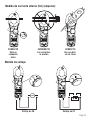
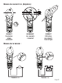
Voltaje de CA Voltaje de CC
Medida de voltaje:
CORRECTO
Uso con divi-
sor de línea
INCORRECTO
Las corrientes
se anulan
CORRECTO
Sólo un
conductor
único
Medida de corriente alterna (CA) (amperes):
NCV
OFF
V
Ω
V
True RMS
40
A
600
AM
HOLD
DC
K
AC
mΩV
APO
CAT.III
600V
600A
CLAMP
61-746
CAT.III
600V
V/Ω
COM
NCV
OFF
V
Ω
V
True RMS
40
A
600
AM
HOLD
DC
K
AC
mΩV
APO
CAT.III
600V
600A
CLAMP
61-746
CAT.III
600V
V/Ω
COM
NCV
OFF
V
Ω
V
True RMS
40
A
600
AM
HOLD
DC
K
AC
mΩV
APO
CAT.III
600V
600A
CLAMP
61-746
CAT.III
600V
V/Ω
COM
H
N
NCV
OFF
V
Ω
V
True RMS
40
A
600
AM
HOLD
DC
K
AC
mΩV
APO
CAT.III
600V
600A
CLAMP
61-746
CAT.III
600V
V/Ω
COM
CAT.III
600V
V/Ω
COM
NCV
OFF
V
Ω
V
True RMS
40
A
600
AM
HOLD
DC
K
AC
mΩV
APO
CAT.III
600V
600A
CLAMP
61-746
NCV
OFF
V
Ω
V
True RMS
40
A
600
AM
HOLD
DC
K
AC
mΩV
APO
CAT.III
600V
600A
CLAMP
61-746
CAT.III
600V
V/Ω
COM
CAT.III
600V
V/Ω
COM
NCV
OFF
V
Ω
V
True RMS
40
A
600
AM
HOLD
DC
K
AC
mΩV
APO
CAT.III
600V
600A
CLAMP
61-746
NCV
OFF
V
Ω
V
True RMS
40
A
600
AM
HOLD
DC
K
AC
mΩV
APO
CAT. III
600V
600A
CLAMP
61-746
CAT. III
600V
V/Ω
COM
Page 19

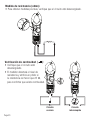
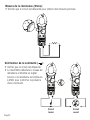
Medida de resistencia (ohms):
• Para obtener medidas precisas, verifique que el circuito esté desenergizado.
CAT.III
COMV/Ω
600V
NCV
OFF
V
Ω
V
True RMS
40
A
600
AM
HOLD
DC
K
AC
mΩV
APO
CAT.III
600V
600A
CLAMP
61-746
CAT.III
COMV/Ω
600V
NCV
OFF
V
Ω
V
True RMS
40
A
600
AM
HOLD
DC
K
AC
mΩV
APO
CAT.III
600V
600A
CLAMP
61-746
CAT.III
COMV/Ω
600V
NCV
OFF
V
Ω
V
True RMS
40
A
600
AM
HOLD
DC
K
AC
mΩV
APO
CAT.III
600V
600A
CLAMP
61-746
CAT.III
COMV/Ω
600V
NCV
OFF
V
Ω
V
True RMS
40
A
600
AM
HOLD
DC
K
AC
mΩV
APO
CAT.III
600V
600A
CLAMP
61-746
CAT.III
COMV/Ω
600V
NCV
OFF
V
Ω
V
True RMS
40
A
600
AM
HOLD
DC
K
AC
mΩV
APO
CAT.III
600V
600A
CLAMP
61-746
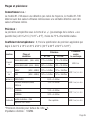
Verificación de continuidad ( ):
• Verifique que el circuito esté
desenergizado.
• El medidor detectará el nivel de
resistencia y emitirá un pitido si
la resistencia es menor que 25 Ω,
para confirmar que existe continuidad.
Circuito
cerrado
Circuito
interrumpido
Page 20
La page est en cours de chargement...
La page est en cours de chargement...
La page est en cours de chargement...
La page est en cours de chargement...
La page est en cours de chargement...
La page est en cours de chargement...
La page est en cours de chargement...
La page est en cours de chargement...
La page est en cours de chargement...
La page est en cours de chargement...
La page est en cours de chargement...
La page est en cours de chargement...
La page est en cours de chargement...
La page est en cours de chargement...
La page est en cours de chargement...
La page est en cours de chargement...
-
 1
1
-
 2
2
-
 3
3
-
 4
4
-
 5
5
-
 6
6
-
 7
7
-
 8
8
-
 9
9
-
 10
10
-
 11
11
-
 12
12
-
 13
13
-
 14
14
-
 15
15
-
 16
16
-
 17
17
-
 18
18
-
 19
19
-
 20
20
-
 21
21
-
 22
22
-
 23
23
-
 24
24
-
 25
25
-
 26
26
-
 27
27
-
 28
28
-
 29
29
-
 30
30
-
 31
31
-
 32
32
-
 33
33
-
 34
34
-
 35
35
-
 36
36


Ideal 600A AC Clamp-Pro™ Clamp Meter Mode d'emploi
- Catégorie
- Mesure, test
- Taper
- Mode d'emploi