Cordless Impact Driver/Wrench
Akku-Schlagschrauber
Perceuse/visseuse à percussion sur batterie
Avvitatore a impulso a batteria per viti e bulloni
Snoerloze slagschroevendraaier/sleutel
Atornillador/Llave de impacto a batería
Aparafusadora/ Chave de impacto a bateria
¢Ú··ÓÔηÙÛ¿‚È‰Ô ª·Ù·Ú›·˜/∫ÏÂȉ›
Read through carefully and understand these instructions before use.
Diese Anleitung vor Benutzung des Werkzeugs sorgfältig durchlesen und verstehen.
Lire soigneusement et bien assimiler ces instructions avant usage.
Prima dell’uso leggere attentamente e comprendere queste istruzioni.
Deze gebruiksaanwijzing s.v.p. voor gebruik zorgvuldig doorlezen.
Leer
cuidadosamente y comprender estas instrucciones antes del uso.
Antes de usar, leia com cuidado para assimilar estas instruções.
∆ιαάστε πρσεκτικά και κατανήσετε αυτές τις δηγίες πριν τη ρήση.
Handling instructions
Bedienungsanleitung
Mode d’emploi
Istruzioni per l’uso
Gebruiksaanwijzing
Instrucciones de manejo
Instruções de uso
δηγίες ειρισµύ
English
EC DECLARATION OF CONFORMITY
We declare under our sole responsibility that this
product is in conformity with standards or standardized
documents EN50144 and EN55014-2 in accordance with
Council Directives 89/336/EEC and 98/37/EC.
This declaration is applicable to the product affixed CE
marking.
Deutsch
ERKLÄRUNG ZUR KONFORMITÄT MIT CE-REGELN
Wir erklären mit alleiniger Verantwortung, daß dieses
Produkt den Standards oder standardisierten
Dokumenten EN50144 und EN55014-2 in
Übereinstimmung mit den Direktiven des Europarats
89/336/EWG und 98/37/CE entspricht.
Diese Erklärung gilt für Produkte, die die CE-Markierung
tragen.
Français
DECLARATION DE CONFORMITE CE
Nous déclarons sous notre seule et entière responsabilité
que ce produit est conforme aux normes ou documents
normalisés EN50144 et EN55014-2 en accord avec les
Directives 89/336/CEE et 98/37/CE du Conseil.
Cette déclaration s’applique aux produits désignés CE.
Italiano
DICHIARAZIONE DI CONFORMITÀ CE
Si dichiara sotto nostra responsabilità che questo
prodotto è conforme agli standard o ai documenti
standardizzati EN50144 e EN55014-2 conforme alle
direttive 89/336/CEE e 98/37/CE del concilio.
Questa dichiarazione è applicabile ai prodotti cui sono
applicati i marchi CE.
412
Code No. C99129872 N
Printed in Japan
Hitachi Koki Co., Ltd.
Variable speed
WH 12DM2 • WR 12DM2 • WH 12DMR
WH 9DM2 • WR 9DM2
Representative office in Europe
Hitachi Power Tools Europe GmbH
Siemensring 34, 47877 Willich 1, F. R. Germany
Head office in Japan
Hitachi Koki Co., Ltd.
Shinagawa Intercity Tower A, 15-1, Konan 2-chome,
Minato-ku, Tokyo, Japan
30. 7. 2004
K. Kato
Board Director
1
4
3
6
5
87
1
I
Nederlands
EC VERKLARING VAN CONFORMITEIT
Wij verklaren onder eigen verantwoordelijkheid dat dit
produkt conform de richtlijnen of gestandardiseerde
documenten EN50144 en EN55014-2 voldoet aan de
eisen van EEG Bepalingen 89/336/EEG en 98/37/EC.
Deze verklaring is van toepassing op produkten
voorzien van de CE-markeringen.
Español
DECLARACIÓN DE CONFORMIDAD DE LA CE
Declaramos bajo nuestra única responsabilidad que
este producto está de acuerdo con las normas o con
los documentos de normalización EN50144 y EN55014-
2 según indican las Directrices del Consejo 89/336/CEE
y 98/37/CE.
Esta declaración se aplica a los productos con marcas
de la CE.
Português
DECLARAÇÃO DE CONFORMIDADE CE
Declaramos, sob nossa única e inteira responsabilidade,
que este produto está de acordo com as normas ou
documentos normativos EN50144 e EN55014-2 em
conformidade com as Diretrizes 89/336/CEE e 98/37/CE
do Conselho.
Esta declaração se aplica aos produtos designados CE.
Ελληνικά
EK ∆ΗΛΩΣΗ ΕΝΑΡΜΝΙΣΜΥ
∆ηλώνυµε µε απ'λυτη υπευθυν'τητα 'τι αυτ' τ
πρι'ν είναι εναρµνισµέν µε τα πρ'τυπα ή τα
έγρα)α πρτύπων EN50144 και EN55014-2 σε
συµ)ωνία µε τις δηγίες τυ Συµυλίυ 89/336/EOK
και 98/37/EK.
Αυτή η δήλωση ισύει στ πρι'ν µε τ σηµάδι EC.
1
F
E
2
4
3
1
5
6
9
8
7
B
C
0
A
D
F
D
G
H
F
D
J
WH12DM2 WR12DM2
1
3
2
3
WH12DMR
D
I
K
F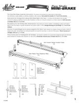

2
3
1211
14
13
O
Q
P
109
L
R
XX
16
15
2019
21
1817
L
(A)
5
4
1
(B)
2
3
M
N
3
L
R
L
T
S
U
V
U
T
,
.
,.
Y
Z
[
3mm
11.5mm
128
\
W

2
3
1211
14
13
O
Q
P
109
L
R
XX
16
15
2019
21
1817
L
(A)
5
4
1
(B)
2
3
M
N
3
L
R
L
T
S
U
V
U
T
,
.
,.
Y
Z
[
3mm
11.5mm
128
\
W

4
English Deutsch Français Italiano
1
2
3
4
5
6
7
8
9
0
A
B
C
D
E
F
G
H
I
J
K
L
M
N
O
P
Q
R
S
T
U
V
W
X
Y
Z
[
\
12 V Rechargeable
battery (For WH12DM2,
WR12DM2, WH12DMR)
9.6 V Rechargeable
battery (For WH9DM2,
WR9DM2)
Latch
Handlee
Insert
Pull out
Insert
Pilot lamp
Hole for connecting the
rechargeable battery
Movement
Guide sleeve
Hexagonal hole in the
anvil
Driver bit
Hexagonal socket
Groove
Anvil
Pin
Ring
Hole
Plunger
Retaining ring
Hook
Spring
Larger diameter faces
away
Switch
Phillips-head screwdriver
Screw
Arrow
Hook cover
Indentation
Protuberance
AAAA batteries
Push button
Push
Wear limit
Nail of carbon brush
Protrusion of carbon
brush
Contact portion outside
brush tube
Batteria ricaricabile,
12 V (Per WH12DM2,
WR12DM2, WH12DMR)
Batteria ricaricabile,
9,6 V (Per WH9DM2,
WR9DM2)
Fermo
Impugnatura
Inserire
Estrarre
Inserire
Spia
Foro di collegamento
della batería recargable
Movimento
Manicotto guida
Foro esagonale nel
basaménto
Testa avvitatrice
Chiave de incavo
esagonale
Scanalature
Basamento
Spina
Anello
Foro
Stantuffo
Anello di trattenimento
Grancio
Molla
Diametro più grande
lontano da sé
Interruttore
Cacciavite con testa a
croce
Vite
Freccia
Coperchio gancio
Tacca
Sporgenza
Pile AAAA
Tasto da premere
Spingere
Limite di usura
Chiodo di spazzola di
carbone
Sporgenza di spazzola
di carbone
Parte di contatto fuori
dal tubo spazzola
Akkumulator, 12 V
(Für WH12DM2,
WR12DM2, WH12DMR)
Akkumulator, 9,6 V
(Für WH9DM2,
WR9DM2)
Schnapper
Griff
Einsatz
Herausziehen
Einsetz
Kontrollampe
Anschlußlon für
Akkumulator
Bewegung
Führungsmanschette
Sechskantloch in der
Schabotte
Dreherspitze
Sechskantbuchse
Schlitz
Schabotte
Stift
Ring
Öffnung
Preßkolben
Haltering
Haken
Feder
Der große Durchmesser
weist zur anderen Seite
Schalter
Kreuzschlitzschrauben-
zieher
Schraube
Pfeil
Hakenabdeckung
Einkerbung
Vorsprung
Batterien der Größe
AAAA
Druckknopf
Drücken
Verschließgrenze
Klaue der Kohlebürste
Krempe der Kohlebürste
Kontaktteil außerhalb
des Bürstenrohrs
Batterie rechargeable,
12 V (Pour WH12DM2,
WR12DM2, WH12DMR)
Batterie rechargeable,
9,6 V (Pour WH9DM2,
WR9DM2)
Loquet
Poignée
Insérer
Tirer
Insérer
Lampe pilote
Orifice de raccordement
de la batterie rechargeable
Mouvement
Manchon-guide
Orifice hexagonal de la
chabotte
Mèche
Douille hexagonal
Rainure
Chabotte
Goupille
Aunneau
Orifice
Piston
Bague de retenue
Crochet
Ressort
Gros diamètre dirigé
vers l’extérieur
Interrupteur
Tournevis à tête Phillips
Vis
Flèche
Cache de crochet
Entaille
Saillie
Piles AAAA
Poussoir
Pousser
Limite d'usure
Clou de balai en
carbone
Saillie de balai en
carbone
Section de contact à
l’extérieur du tube de
balai

5
Nederlands Español Português Ελληνικά
1
2
3
4
5
6
7
8
9
0
A
B
C
D
E
F
G
H
I
J
K
L
M
N
O
P
Q
R
S
T
U
V
W
X
Y
Z
[
\
Oplaadbare batterij, 12 V
(Voor WH12DM2,
WR12DM2, WH12DMR)
Oplaadbare batterij, 9,6
V (Voor WH9DM2,
WR9DM2)
Vergrendeling
Handgreep
Insteken
Uittrekken
Insteken
Kontrolelampje
Aansluiting voor
oplaadbare batterij
Beweging
Geleide ring
Zeshoekige opening in
het draaistuk
Schroefstuk
Zeschoekige bus
Groef
Draaistuk
Pen
Ring
Opening
Plunjer
Borgring
Haak
Veer
De grotere diameter wijst
van u vandaan
Schakelaar
Kruiskopschroevendraaier
Schroef
Pijl
Afdekking haak
Inkeping
Uitsteeksel
AAAA batterijen
Druktoets
Drukken
Slijtagegrens
Nagel van koolborstel
Uitsteeksel van
koolborstel
Contact-gedeelte buiten
de borstelbuis
12 V Επαναρτιµενη
µπαταρία (Για WH12DM2,
WR12DM2, WH12DMR)
9,6 V Επαναρτιµενη
µπαταρία (Για WH9DM2,
WR9DM2)
Μάνδαλ
ερύλι
Εισωρήστε
Βραήτε έω
Εισωρήστε
∆κιµαστική λάµπα
Τρύπα για την σύνδεση
της επαναρτιµενης
µπαταρίας
Κίνηση
%δηγητικς ραίνας
Εάγωνη τρύπα στν
άκµνα
Λεπίδα κίνησης
Μακριά υπδή
Αυλάκωση
Άκµνας
Πείρς
∆ακτύλις
Τρύπα
Έµλ
∆ακτύλις συγκράτησης
Άγκιστρ
Ελατήρι
Η µεγαλύτερη
διάµετρς λέπει πρς
άλλη κατεύθυνση
∆ιακπτης
Κατσαίδι κεαλής
Phillips
Βίδα
Βέλς
Κάλυµµα αγκίστρυ
Αυλάκωση
Πρεή
ΑΑΑΑ µπαταρίες
Κυµπί ώθησης
Σπρώε
5ρι θράς
Καρί καρυνακιύ
Πρεή
καρυνακιύ
Τµήµα επαής έω
απ τ σωλήνα της
ψήκτρας
Bateria de 12 V recarregável
(Para WH12DM2,
WR12DM2, WH12DMR)
Bateria de 9,6 V
recarregável (Para
WH9DM2, WR9DM2)
Lingüeta
Cabo
Inserir
Retirar
Inserir
Lâmpada piloto
Orifício para conectar a
bateria recarregável
Movimento
Manga-guia
Orifício sextavado na
bigorna
Chave de fenda
Encaixe longo
Ranhura
Bigorna
Pino
Anel
Orifício
Pistão
Anel de retenção
Gancho
Mola
O diâmetro maior dá
para fora
Comutador
Chave Phillips
Parafuso
Seta
Tampa do gancho
Entalhe
Protuberância
Pilhas AAAA
Interruptor
Apertar
Limite de desgaste
Prego da escova de
carvão
Saliência da escova de
carvão
Segmento de contato
no exterior do tubo da
escova
Batería recargable,
12 V (Para WH12DM2,
WR12DM2, WH12DMR)
Batería recargable,
9,6 V (Para WH9DM2,
WR9DM2)
Enganche
Mango
Insertar
Sacar
Insertar
Lámpara piloto
Agujero para conectar
la batería recargable
Movimiento
Manguito guía
Orificio hexagonal en el
yunque
Punta de destornillador
Recaptáculo hexanogal
Ranura
Yunque
Pasador
Anillo
Orificio
Embolo
Anillo de retención
Gancho
Resorte
El diámetro más grande
queda en dirección
opuesta
Interruptor
Destornillador con cabeza
Phillips
Tornillo
Flecha
Cubierta del gancho
Indentación
Saliente
Pilas AAAA
Pulsador
Presionar
Límite de uso
Uña de escobilla de
carbón
Saliente de escobilla de
carbón
Tubo exterior de la
parte de contacto de la
escobilla de carbón

English
6
GENERAL OPERATIONAL PRECAUTIONS
1. Keep work area clean. Cluttered areas and benches
invite accidents.
2. Avoid dangerous environment. Don’t expose power
tools and charger to rain. Don’t use power tools
and charger in damp or wet locations. And keep
work area well lit. Never use power tools and
charger near flammable or explosive materials.
Do not use tool and charger in presence of
flammable liquids or gases.
3. The appliance is not intended for use by young
children or infirm persons without supervision.
Young children should be supervised to ensure
that they do not play with the appliance. All visitors
should be kept safe distance from work area.
4. Store idle tools and charger. When not in use,
tools and charger should be stored in dry, high
or locked-up place – out of reach of the children
and infirm persons. Store tools and charger in a
place where the temperature is less than 40°C.
5. Don’t force tool. It will do the job better and safer
at the rate for which it was designed.
6. Use right tool. Don’t force small tool or attachment
to do the job of a heavy duty tool.
7. Wear proper apparel. Do not wear loose clothing
or jewelry. They can be caught in moving parts.
Rubber gloves and non-skid footwears are
recommended when working outdoor.
8. Use eye protection with most tools. Also use face
or dust mask if cutting operation is dusty.
9. Don’t abuse cord. Never carry charger by cord or
yank it to disconnect from receptacle. Keep cord
from heat, oil and sharp edges.
10. Secure work. Use clamps or a vise to hold work.
It’s safer than using your hand and it frees both
hands to operate tool.
11. Don’t overreach. Keep proper footing and balance
at all times.
12. Maintain tools with care. Keep tools sharp at all
times, and clean for best and safest performance.
Follow instructions for lubricating and changing
accessories.
13. When the charger is not in use, or when being
maintained and inspected, disconnect its power
cord from the receptacle.
14. Remove chuck wrenches and wrenches. Form habit
of checking to see that wrenches are removed
from tool before turning it on.
15. Avoid accidental starting. Don’t carry tool with
finger on switch.
16. To avoid danger, always use only the specified
charger.
17. Use only genuine HITACHI replacement parts.
18. Do not use power tools for applications other than
those specified in the Handling Instructions.
19. To avoid personal injury, use only the accessories
or attachment recommended in these handling
instructions or in the HITACHI catalog.
20. Let only the authorized service center do the
repairing. The Manufacturer will not be responsible
for any damages or injuries caused by repair by
the unauthorized persons or by mishandling of
the tool.
21. To ensure the designed operational integrity of
power tools and charger, do not remove installed
covers or screws.
22. Always use the charger at the voltage specified
on the nameplate.
23. Do not touch movable parts or accessories unless
the power source has been disconnected.
24. Always charge the battery before use.
25. Never use a battery other than that specified. Do
not connect a usual dry cell, a rechargeable battery
other than that specified or a car battery to the
power tool.
26. Do not use any transformer that has a booster.
27. Do not charge the battery from an engine electric
generator or DC power supply.
28. Always charge indoors. Because the charger and
battery heat slightly during charging, charge the
battery in a place not exposed to direct sunlight;
where the humidity is low and the ventilation is
good.
29. Before starting to work in a high place, pay
attention to the activities below to make sure
there are no people below.
30. Use the exploded assembly drawing on this
handling instructions only for authorized servicing.
31. If the supply cord is damaged, it must be replaced
by the manufacture or its service agent or a
similarly qualified person in order to avoid a
hazard.
PRECAUTIONS FOR CORDLESS IMPACT
DRIVER
1. This is portable tool for tightening and loosenig
screws. Use it only for these operation.
2. Use the earplugs if using for a long time.
3. One-hand operation is extremely dangerous; hold
the unit firmly with both hands when operating.
4. After installing the driver bit, pull lightly out the
bit to make sure that it does not come loose. If
the bit is not installed properly, it can come loose
during use, which can be dangerous.
5. Use the bit that matches the screw.
6. Tightening a screw with the impact driver at an
angle to that screw can damage the head of the
screw and the proper force will not be transmitted
to the screw. Tighten with this impact driver lined
up straight with the screw.
7. Always charge the battery at a temperature of 0
– 40°C.
A temperature of less than 0°C will result in over
charging which is dangerous. The battery cannot
be charged at a temperature greater than 40°C.
The most suitable temperature for charging is that
of 20 – 25°C.
8. Do not use the charger continuously.
When one charging is completed, leave the charger
for about 15 minutes before the next charging of
battery.
9. Do not allow foreign matter to enter the hole for
connecting the rechargeable battery.
10. Never disassemble the rechargeable battery and
charger.
11. Never short-circuit the rechargeable battery.
Short-circuiting the battery will cause a great
electric current and overheat. It results in burn or
damage to the battery.
12. Do not dispose of the battery in fire.
If the battery burnt, it may explode.
13. Do not insert object into the air ventilation slots
of the charger.
Inserting metal objects or inflammables into the
charger air ventilation slots will result in electrical
shock hazard or damaged charger.
14. Bring the battery to the shop from which it was
purchased as soon as the post-charging battery
life becomes too short for practical use. Do not
dispose of the exhausted battery.
15. Using an exhausted battery will damage the
charger.

English
7
PRECAUTIONS FOR CORDLESS IMPACT
WRENCH
1. This is a portable tool for tightening and loosening
bolts and nuts. Use it only for these operation.
2. Use the earplugs if using for a long time.
3. One-hand operation is extremely dangerous; hold
the unit firmly with both hands when operating.
4. Check that the socket is not cracked or broken.
Broken or cracked sockets are dangerous. Check
the socket before using it.
5. Secure the socket with the socket pin and the ring.
If the socket pin or ring securing the socket is damaged,
the socket may come off from the impact wrench,
which is quite dangerous. Do not use socket pins
or rings that are deformed, worn out, cracked, or in
any other way damaged. Always make sure to install
the socket pin and ring in the correct position.
6. Check the tightening torque.
The appropriate torque for tightening a bolt
depends on the material the bolt is made of, its
dimensions, grade, etc.
Also, the tightening torque generated by this impact
wrench depends on the materials and dimensions
of the bolt, how long the impact wrench is applied
for the way in which the socket is installed, etc.
Also the torque when the battery has just been
charged and when it is about to run out are slightly
different. Use a torque wrench to check that the
bolt has been tightened with the appropriate torque.
7. Stop the impact wrench before switching the
direction of rotation. Always release the switch
and wait for impact wrench to stop before
switching the direction of rotation.
8. Never touch the turning part.
Do not allow the turning socket section to get near
your hands or any other part of your body. You could
be cut or caught in the socket. Also, be careful not
to touch the socket after using continuously it for a
long time. It gets quite hot and could burn you.
9. Never let the impact wrench turn without a load
when using the universal joint.
If the socket turns without being connected to a load,
the universal joint causes the socket to turn wildly.
You could get hurt or the movement of the socket
could shake the impact wrench so much as to
make you drop it.
10. Always charge the battery at a temperature of 0
– 40°C.
A temperature of less than 0°C will result in over
charging which is dangerous. The battery cannot
be charged at a temperature greater than 40°C.
The most suitable temperature for charging is
that of 20 – 25°C.
11. Do not use the charger continuously.
When one charging is completed, leave the charger
for about 15 minutes before the next charging of
battery.
12. Do not allow foreign matter to enter the hole for
connecting the rechargeable battery.
13. Never disassemble the rechargeable battery and
charger.
14. Never short-circuit the rechargeable battery.
Short-circuiting the battery will cause a great
electric current and overheat. It results in burn
or damage to the battery.
15. Do not dispose of the battery in fire.
If the battery burnt, it may explode.
16. Do not insert object into the air ventilation slots
of the charger.
Inserting metal objects or inflammables into the
charger air ventilation slots will result in electrical
shock hazard or damaged charger.
17. Bring the battery to the shop from which it was
purchased as soon as the post-charging battery
life becomes too short for practical use. Do not
dispose of the exhausted battery.
18. Using an exhausted battery will damage the
charger.
MODEL
WH12DM2: with charger and case
WH9DM2: with charger and case
WH12DMR: with charger and case
WR12DM2: with charger and case
WR9DM2: with charger and case
SPECIFICATIONS
Cordless Impact Driver
Model WH9DM2 (9.6 V) WH12DM2 (12 V) WH12DMR (12 V)
No-load speed 0 – 2800 min
–1
0 – 2600 min
–1
Capacity M4 – M8 (Small screw)
M5 – M12 (Ordinary bolt)
M5 – M10 (High tension bolt)
Tightening torque
Rechargeable battery
EB9B: Ni-Cd battery, 9.6 V
EB1220BL: Ni-Cd battery, 12 V
(2.0 Ah 8 cells) (2.0 Ah 10 cells)
EB926H: Ni-MH battery, 9.6 V
EB1226HL: Ni-MH battery, 12 V
(2.6 Ah 8 cells) (2.6 Ah 10 cells)
EB930H: Ni-MH battery, 9.6 V
EB1230HL: Ni-MH battery, 12 V
(3.0 Ah 8 cells) (3.0 Ah 10 cells)
Weight 1.2 kg 1.6 kg
Maximum 80 N·m
{820 kgf·cm}
Tightening is M12 high
tension bolt (strength
grade 12.9), when fully
charged at 20°C temp.
Tightening time: 3 sec.
Maximum 135 N·m Maximum 130 N·m
{1375 kgf·cm}
{1330 kgf·cm}
Tightening is M14 high tension bolt (strength grade
12.9), when fully charged at 20°C temp.
Tightening time: 3 sec.

English
8
Part Name
Engraved
LBCode No.
characters
5 mm Hexagonal socket 8 65 8 996177
6 mm Hexagonal socket 10 65 10 985329
5/16" Hexagonal socket 12 65 12 996178
8 mm Hexagonal socket 13 65 13 996179
Bit No. Code No.
No. 2 992671
No. 3 992672
CHARGER
Model UC14YFA
Charging time EB9B, EB1220BL: Approx. 50 min. (at 20°C)
EB926H, EB1226HL: Approx. 65 min. (at 20°C)
EB930H, EB1230HL: Approx. 70 min. (at 20°C)
Charging voltage 7.2 – 14.4 V
Weight 0.6 kg
Model WR9DM2 (9.6 V) WR12DM2 (12 V)
No-load speed 0 – 2600 min
–1
Capacity M6 – M14 (Ordinary bolt) M6 – M16 (Ordinary bolt)
M6 – M10 (High tension bolt) M6 – M12 (High tension bolt)
Tightening torque
Rechargeable battery EB9B: Ni-Cd battery, 9.6 V EB1220BL: Ni-Cd battery, 12 V
(2.0 Ah 8 cells) (2.0 Ah 10 cells)
EB930H: Ni-MH battery, 9.6 V EB1230HL: Ni-MH battery, 12 V
(3.0 Ah 8 cells) (3.0 Ah 10 cells)
Weight 1.4 kg 1.6 kg
Maximum 120 N·m
{1220 kgf·cm}
Tightening is M12 high tension bolt
(strength grade 12.9), when fully
charged at 20°C temp.
Tightnening time: 3 sec.
Maximum 165 N·m
{1685 kgf·cm}
Tightening is M16 (F10T), when fully
charged at 20°C temp.
Tightening time: 3 sec.
Cordless Impact Wrench
Part Name
Engraved
LBCode No.
characters
10 mm Hexagonal socket
14 65 14 996180
(small type)
10 mm Hexagonal socket 16 65 16 996181
10 mm Hexagonal socket 17 65 17 996182
1/2" Hexagonal long
socket
21 166 21 996197
Engraved characters
STANDARD ACCESSORIES
1. Charger (UC14YFA) ................................................... 1
2. Plastic case ................................................................ 1
Standard accessories are subject to change without
notice.
OPTIONAL ACCESSORIES
(Sold separately)
<For WH12DM2, WH9DM2, WH12DMR>
1. Plus driver bit
2. Hexagonal socket
3. Wood working drill: Code No. 959183
4. Drill chuck adapter set: Code No. 321823
Use the drills available on the local market.

English
9
<For WR12DM2, WR9DM2>
1. Sockets
Form B Form C
Form D
Code No.
High ISO ISO Inch
Form
tension
(ordinary)
(small) bolts L L1 øF
10 mm 944291 M6 10 B 40 8 18
12 mm 873632 M8 W5/16" 12 B 40 8 20
13 mm 873539 M8 13 B 40 9 25
12.7
Hexagonal
14 mm 873540 M10 14 B 40 9 25
Socket
17 mm 873536 M10 M12 W3/8" 17 C 32 8 28
19 mm 873624 M12 M14 W7/16" 19 C 34 9 28
21 mm 873626 W1/2" 21 D 36 10 32
22 mm 873627 M12 M14 M16 22 D 40 14 35
24 mm 873629 M16 M18 24 D 40 15 38
Square
head drive
dimensions
S (mm)
Part Name
Suitable Bolt Diameter
Hexagonal
width across
flats H (mm)
Main Socket
Dimensions (mm)
Form B Form C
Form D
2. Long Socket
Table 1
H S
L
L1
ØF
H S
L
L1
ØF
H S
L
L1
ØF
H
S
L1
L2
L
ØF
H S
L1
L2
L
ØF
H
S
L1
L2
L
ØF
<For WR12DM2>
<For WR9DM2> Table 2
Code No.
ISO ISO Inch
Form
(ordinary)
(small) bolts L L1 øF
8 mm 996125 M5 8 B 33 5 13
10 mm 996126 M6 10 B 33 6 16
12 mm 996127 M8 W5/16" 12 C 33 7 19
9.5
13 mm 996128 M8 13 B 33 8 20
14 mm 996129 M10 14 B 33 8 21
16 mm 996130 M10 16 D 33 9 24
17 mm 996131 M10 M12 W3/8" 17 D 33 10 25
18 mm 996132 M12 18 D 33 10 26
19 mm 996133 M12 W7/16" 19 D 33 12 27.5
Square
head drive
dimensions
S (mm)
Part Name
Suitable Bolt Diameter
Hexagonal
width across
flats H (mm)
Main Socket
Dimensions (mm)
Hexagonal
Socket

English
10
Table 3
Code No.
High ISO ISO Inch
Form
tension
(ordinary)
(small) bolts L L1 L2 øF
12 mm 955138 M8 W5/16" 12 B 52 20 34 20
13 mm 955139 M8 13 B 52 20 34 21.5
14 mm 955140 M10 14 B 52 20 34 22
17 mm 955141 M10 M12 W3/8" 17 B 52 24 34 25
17 mm 955149 M10 M12 W3/8" 17 B 75 24 57 25
12.7
Long
19 mm 955142 M12 M14 W7/16" 19 B 52 24 34 28
Socket
19 mm 955150 M12 M14 W7/16" 19 B 75 24 57 28
21 mm 955143 W1/2" 21 D 52 24 34 31
21 mm 955151 W1/2" 21 D 75 24 57 31
21 mm 991480 W1/2" 21 D 125 24 107 31
22 mm 955144 M12 M14 M16 22 D 52 24 34 32.5
24 mm 955146 M16 M18 24 D 52 25 34 34
Square
head drive
dimensions
S (mm)
Part Name
Suitable Bolt Diameter
Hexagonal
width across
flats H (mm)
Main Socket
Dimensions (mm)
<For WR12DM2>
<For WR9DM2> Table 4
Code No.
ISO ISO Inch
Form
(ordinary)
(small) bolts L L1 L2 øF
8 mm 996134 M5 8 B 60 12 48 13
10 mm 996135 M6 10 B 60 12 48 16
12 mm 996136 M8 W5/16" 12 C 60 14 48 18.4
9.5
13 mm 996137 M8 13 B 60 14 48 18.9
14 mm 996138 M10 14 B 60 15 48 19.5
16 mm 996139 M10 16 D 60 15 48 24
17 mm 996140 M10 M12 W3/8" 17 D 60 15 48 25
18 mm 996141 M12 18 D 60 16 48 26
19 mm 996142 M12 W7/16" 19 D 60 17 48 27.5
Square
head drive
dimensions
S (mm)
Part Name
Suitable Bolt Diameter
Hexagonal
width across
flats H (mm)
Main Socket
Dimensions (mm)
Long
Socket
3. Extension bar: WR12DM2: Code No. 873633
WR9DM2: Code No. 996143
The extension bar is convenient for working in very
restricted spaces or when the socket provided cannot
reach the bolt to be tightened.
CAUTION:
When the extension bar is used, the tightening torque
is reduced slightly compared with the ordinary socket.
4. Universal joint: WR12DM2: Code No. 992610
WR9DM2: Code No. 996147
The universal joint is convenient for impacting nuts
when there is an angle between the socket and
wrench, or when working in a very narrow space.
5. Duct Socket: (WR12DM2)
This is used for tightening bolts and nuts on flange
sections of air conditioners, type ducts, etc.
6. Corner attachment (Model EW-14R) (WR12DM2)
Use this attachment only when the machine is applied
to the nut or bolt at the right angle.
Code No.
Hexagonal width
across flats (mm)
993658 12
992613 13
992615 14

English
11
7. Bit adaptor: Code No. 322752 (WR12DM2)
This is used for tightening small screws (M6 – M8).
NOTE:
(1) This adaptor is set only on the anvil (drive angle) of
the main unit. The bit adapter cannot be attached to
the special accessory anvil (square drive).
(2) Before starting work with the adapter, tighten a few
screws with it to make sure it’s tightening with the
appropriate torque.
(3) Tightening speed will be greatly reduced when driving
wood, tapping or other similar screws.
Optional accessories are subject to change without notice.
APPLICATION
< WH12DM2, WH9DM2, WH12DMR >
䡬 Driving and removing of small screws, small bolts,
etc.
< WR12DM2, WR9DM2 >
䡬 Tightening and loosening of all types of bolts and
nuts, used for securing structural items
BATTERY REMOVAL/INSTALLATION
1. Battery removal
Hold the handle tightly and push the battery latch to
remove the battery. (See Fig. 1 and 2)
CAUTION:
Never short-circuit the battery.
2. Battery installation
Insert the battery while observing its polarities. (See
Fig. 2)
CHARGING
Before using the impact driver, charge the battery as
follows.
1. Connect the charger’s power cord to a receptacle.
When the power cord is connected, the charger’s
pilot lamp will blink in red. (At 1-second intervals.)
2. Insert the battery into the charger.
Insert the battery firmly, in the direction shown in
Fig. 3, until it contacts the bottom of the charger
compartment.
CAUTION:
䡬 If the battery is inserted in the reverse direction, not
only recharging will become impossible, but it may
also cause problems in the charger such as deformed
recharging terminal.
3. Charging
When inserting a battery in the charger, charging will
commence and the pilot lamp will light up
continuously in red.
When the battery becomes fully recharged, the pilot
lamp will blink in red. (At 1-second intervals.) (See
Table 5)
(1) Pilot lamp indication
The indications of the pilot lamp will be as shown in
Table 5, according to the condition of the charger or
the rechargeable battery.
Lights for 0.5 seconds. Does not light for
0.5 seconds. (off for 0.5 seconds)
Lights continuously
Lights for 0.5 seconds. Does not light for
0.5 seconds. (off for 0.5 seconds)
Lights for 0.1 seconds. Does not light for
0.1 seconds. (off for 0.1 seconds)
Lights continuously
Before
charging
While
charging
Charging
complete
Charging
impossible
Charging
impossible
Blinks
(RED)
Lights
(RED)
Blinks
(RED)
Flikers
(RED)
Lights
(GREEN)
Malfunction in the battery
or the charger
The battery temperature
is high, making
recharging impossible.
Table 5
Indications of the lamps

English
12
(2) Regarding the temperatures of the rechargeable battery
The temperatures for rechargeable batteries are as
shown in the table below, and batteries that have
become hot should be cooled for a while before
being recharged.
Table 6 Recharging ranges of batteries
(3) Regarding recharging time
Depending on the combination of the charger and
batteries, the charging time will become as shown in
Table 7.
Table 7 Charging time (At 20°C)
NOTE:
The charging time may vary according to the ambient
temperature and power source voltage.
4. Disconnect the charger’s power cord from the receptacle.
5. Hold the charger firmly and pull out the battery.
NOTE:
Be sure to pull out the battery from the charger after
use, and then keep it.
Regarding electric discharge in case of new
batteries, etc.
As the internal chemical substance of new batteries
and batteries that have not been used for an extended
period is not activated, the electric discharge might
be low when using them the first and second time.
This is a temporary phenomenon, and normal time
required for recharging will be restored by recharging
the batteries 2 – 3 times.
How to make the batteries perform longer
(1) Recharge the batteries before they become completely
exhausted.
When you feel that the power of the tool becomes
weaker, stop using the tool and recharge its battery.
If you continue to use the tool and exhaust the electric
current, the battery may be damaged and its life will
become shorter.
(2) Avoid recharging at high temperatures.
A rechargeable battery will be hot immediately after
use. If such a battery is recharged immediately after
use, its internal chemical substance will deteriorate,
and the battery life will be shortened. Leave the battery
and recharge it after it has cooled for a while.
CAUTION:
䡬 If the battery is charged while it is heated because it
has been left for a long time in a location subject to
direct sunlight or because the battery has just been
Temperatures at
Rechargeable batteries which the battery
can be recharged
EB1220BL, EB9B –5°C – 60°C
EB1226HL, EB1230HL, EB926H, EB930H
0°C – 45°C
used, the pilot lamp of the charger lights up green. In
such a case, first let the battery cool, then start
charging.
䡬 When the pilot lamp flikers in red quickly (at 0.2-
second intervals), check for and take out any foreign
objects in the charger’s battery installation hole. If
there are no foreign objects, it is probable that the
battery or charger is malfunctioning. Take it to your
Authorized Service Center.
䡬 Since the built-in micro computer takes about 3
seconds to confirm that the battery being charged
with UC14YFA is taken out, wait for a minimum of 3
seconds before reinserting it to continue charging. If
the battery is reinserted within 3 seconds, the battery
may not be properly charged.
PRIOR TO OPERATION
1. Preparing and checking the work environment
Make sure that the work site meets all the conditions
laid forth in the precautions.
2. Checking the battery
Make sure that the battery is installed firmly. If it is at
all loose it could come off and cause an accident.
3. Installing the bit (WH12DM2, WH9DM2, WH12DMR)
Always follow the following procedure to install driver
bit. (Fig. 4)
(1) Pull the guide sleeve away from front of the tool.
(2) Insert the bit into the hexagonal hole in the anvil.
(3) Release the guide sleeve and it returns to its original
position.
CAUTION:
If the guide sleeve does not return to its original
position, then the bit is not installed properly.
4. Selecting the socket matched to the bolt
(WR12DM2, WR9DM2)
Be sure to use a socket which is matched to the bolt
to be tightened. Using an improper socket will not
only result in insufficient tightening but also in
damage to the socket or nut.
A worn or deformed hex. or square-holed socket will
not give an adequate tightness for fitting to the nut or
anvil, consequently resulting in loss of tightening
torque.
Pay attention to wear of socket hole, and replace
before further wear has developed.
Finally, install the socket prescribed in Item 5. The
section on “Optional Accessories” details the
relationship between bolt sizes and sockets. Sockets
are named according to the dihedral width of the
hexagonal hole.
5. Installing a socket (WR12DM2, WR9DM2)
Select the socket to be used.
䢇 Pin, O-ring type (Fig. 5 and 6)
(1) Align the hole in the socket with the hole in the anvil
and insert the anvil into the socket.
(2) Insert the pin into the socket.
(3) Attach the ring to the groove on the socket.
䢇 Plunger type (Fig. 7)
Align the plunger located in the square part of the
anvil with the hole in the hex. socket. Then push the
plunger, and mount the hex. socket on the anvil.
Check that the plunger is fully engaged in the hole.
When removing the socket, reverse the sequence.
Charger
UC14YFA
Battery
EB1220BL, EB9B
Approx. 50 min.
EB1226HL, EB926H
Approx. 65 min.
EB1230HL, EB930H
Approx. 70 min.

English
13
䢇 Retaining ring type (Fig. 8)
(1) Align the square portions of the socket and the anvil
with each other.
(2) Make sure to firmly install the socket by pushing it all
the way into the anvil.
(3) When removing the socket, pull it out of the anvil.
CAUTION:
䡬 Please use the designated attachments which are
listed in the operations manual and Hitachi’s catalog.
Accidents or injuries could result from not doing so.
䡬 Make sure to firmly install the socket in the anvil. If
the socket is not firmly installed it might come out
and cause injuries.
HOW TO USE
CAUTION:
䡬 When using the light equipped hook, pay sufficient
attention so that the main equipment does not fall. If
the tool falls, there is a risk of accident.
䡬 Do not attach the tip tool except phillips bit to the tool
main unit when carrying the tool main unit with the
light equipped hook suspended from a waist belt.
Injury may result if you carry the equipment
suspended from the waist belt with sharp tipped
components such as drill bit attached.
1. Using the light equipped hook
The light equipped hook can be installed on the right
or left side and the angle can be adjusted in 5 steps
between 0° and 80°.
(1) Operating the hook
(a) Pull out the hook toward you in the direction of
arrow (A) and turn in the direction of arrow (B).
(Fig. 9)
(b) The angle can be adjusted in 5 steps (0°, 20°, 40°,
60°, 80°).
Adjust the angle of the hook to the desired position
for use.
(2) Switching the hook position
CAUTION:
Incomplete installation of the hook may result in
bodily injury when used.
(a) Securely hold the main unit and remove the screw
using a slotted head screwdriver or a coin. (Fig.
10)
(b) Remove the hook and spring. (Fig. 11)
(c) Install the hook and spring on the other side and
securely fasten with screw. (Fig. 12)
NOTE:
Pay attention to the spring orientation. Install the
spring with larger diameter away from you. (Fig. 12)
(3) Using as an auxiliary light
(a) Press the switch to turn off the light.
If forgotten, the light will turn off automatically
after 15 minutes.
(b) The direction of the light can be adjusted within
the range of hook positions 1 - 5. (Fig. 13)
䡬 Lighting time
AAAA manganese batteries: approx. 15 hrs.
AAAA alkali batteries: approx. 30 hrs.
CAUTION:
Do not look directly into the light.
Such actions could result in eye injury.
(4) Replacing the batteries
(a) Loosen the hook screw with a phillips-head
screwdriver (No. 1). (Fig. 14)
Remove the hook cover by pushing in the direction
of the arrow. (Fig. 15)
(b) Remove the old batteries and insert the new
batteries. Align with the hook indications and
position the plus (+) and minus (–) terminals
correctly. (Fig. 16)
(c) Align the indentation in the hook main body with
the protuberance of the hook cover, press the
hook cover in the direction opposite to that of the
arrow shown in Fig. 15 and then tighten the screw.
Use commercially available AAAA batteries
(1.5 V).
NOTE:
Do not tighten the screw excessively. Such action
could strip the screw threads.
CAUTION:
䡬 Failure to observe the following can result in battery
leakage, rust or malfunction.
Position the plus (+) and minus (–) terminals correctly.
Replace both batteries at the same time. Do not mix
old and new batteries.
Remove exhausted batteries from the hook
immediately.
䡬 Do not discard batteries together with normal trash
and do not throw batteries into fire.
䡬 Store batteries out of the reach of children.
䡬 Use batteries correctly in accordance with the battery
specifications and indications.
2. Check the rotational direction
The bit rotates clockwise (viewed from the rear side)
by pushing the R-side of the push button.
The L-side of the push button is pushed to turn the bit
counterclockwise. (See Fig. 17) (The
L
and
R
marks
are provided on the body.)
CAUTION:
The push button cannot be switched while the impact
driver is turning. To switch the push button, stop the
impact driver, then set the push button.
3. Switch operation
䡬 When the trigger switch is depressed, the tool rotates.
When the trigger is released, the tool stops.
䡬 The rotational speed can be controlled by varying the
amount that the trigger switch is pulled. Speed is low
when the trigger switch is pulled slightly and increases
as the trigger switch is pulled more.
4. Tightening and loosening screws (WH12DM2,
WH9DM2, WH12DMR)
Install the bit that matches the screw, line up the bit
in the grooves of the head of the screw, then tighten
it.
Push the impact driver just enough to keep the bit
fitting the head of the screw.
CAUTION:
Applying the impact driver for too long tightens the
screw too much and can break it.
Tightening a screw with the impact driver at an angle
to that screw can damage the head of the screw and
the proper force will not be transmitted to the screw.
Tighten with this impact driver lined up straight with
the screw.

English
14
5. Number of screws tightenings possible (WH12DM2,
WH9DM2, WH12DMR)
Please refer to the table below for the number of
screw tightened possible with one charge.
WH12DM2, WH12DMR (EB1230HL)
WH9DM2 (EB930H)
These values may vary slightly, according to
surrounding temperature and battery characteristics.
6. Number of bolt tightened possible (WR12DM2,
WR9DM2)
Please refer to the table below for the number of bolt
tightened possible with one charge.
WR12DM2 (EB1230HL)
WR9DM2 (EB930H)
These values may vary slightly, according to
surrounding temperature and battery characteristics.
NOTE:
The use of the battery EB1230HL, EB930H in a cold
condition (below 0 degree Centigrade) can sometimes
result in the weakened tightening torque and reduced
amount of work. This, however, is a temporary
phenomenon, and returns to normal when the battery
warms up.
OPERATIONAL CAUTIONS
1. Resting the unit after continuous work
After use for continuous bolt-tightening work, rest
the unit for 15 minutes or so when replacing the
battery. The temperature of the motor, switch, etc.,
will rise if the work is started again immediately after
battery replacement, eventually resulting in burnout.
NOTE:
Do not touch the protector, as it gets very hot during
continuous work.
2. Cautions on use of the speed control switch
This switch has a built-in, electronic circuit which
steplessly varies the rotation speed. Consequently,
when the switch trigger is pulled only slightly (low
speed rotation) and the motor is stopped while
continuously driving in screws, the components of
Screw used No. of tightenings
Wood screw ø4 × 50
Approx. 530
(Soft wood)
Machine screw M8 × 16 Approx. 1690
Bolt used No. of tightenings
M12 Hightension bolt Approx. 180
Bolt used No. of tightenings
M12 Hightension bolt Approx. 120
the electronic circuit parts may overheat and be
damaged.
3. Tightening torque
Refer to Fig. 22, 23, 24, 25 and Fig. 26 for the tightening
torque of bolts (according to size), under the
conditions shown in Fig. 27. Please use this example
as a general reference, as tightening torque will vary
according to tightening conditions.
NOTE:
䡬 If a long striking time is used, screws will be strongly
tightened. This may cause the screw to break, or may
damage the tip of the bit.
䡬 If the unit is held at an angle to the screw being
tightened, the head of the screw may be damaged, or
the specified torque may not be transmitted to the
screw. Always keep the unit and the screw being
tightened in a straight line.
4. Use a tightening time suitable for the screw
The appropriate torque for a screw differs according
to the material and size of the screw, and the material
being screwed etc., so please use a tightening time
suitable for the screw. In particular, if a long tightening
time is used in the case of screws smaller than M8,
there is a danger of the screw breaking, so please
confirm the tightening time and the tightening torque
beforehand.
5. Work at a tightening torque suitable for the bolt
under impact
The optimum tightening torque for nuts or bolts differs
with material and size of the nuts or bolts. An
excessively large tightening torque for a small bolt
may stretch or break the bolt. The tightening torque
increases in proportion to the operaton time. Use the
correct operating time for the bolt.
6. Holding the tool
Hold the impact wrench firmly with both hands. In
this case hold the wrench in line with the bolt.
It is not necessary to push the wrench very hard.
Hold the wrench with a force just sufficient to
counteract the impact force.
7. Confirm the tightening torque
The following factors contribute to a reduction of the
tightening torque. So confirm the actual tightening
torque needed by screwing up some bolts before the
job with a hand torque wrench. Factors affecting the
tightening torque are as follows.
(1) Voltage
When the discharge margin is reached, voltage
decreases and tightening torque is lowered.
(2) Operating time
The tightening torque increases when the operating
time increases. But the tightening torque does not
increase above a certain value even if the tool is
driven for a long time. (See Fig. 22, 23, 24, 25 and 26)
(3) Diameter of bolt
The tightening torque differs with the diameter of the
bolt as shown in Fig. 22, 23, 24, 25 and 26. Generally a
larger diameter bolt requires larger tightening torque.
(4) Tightening conditions
The tightening torque differs according to the torque
ratio; class, and length of bolts even when bolts with
the same size threads are used. The tightening torque
also differs according to the condition of the surface
of workpiece through which the bolts are to be
tightened. When the bolt and nut turn together, torque
is greatly reduced.
Screw used
No. of tightenings
WH12DM2 WH12DMR
Wood screw ø4 × 50
Approx. 790 Approx. 750
(Soft wood)
Machine screw M8 × 16
Approx. 1750 Approx. 1660

English
15
M12 × 45
kgf·cm
1200
1000
800
600
400
200
0
N·m
120
100
80
60
40
20
0
0 1 2 3
M10 × 30
kgf·cm
1000
800
600
400
200
0
N·m
100
80
60
40
20
0
0
1 2 3
M8 × 30
kgf·cm
1000
800
600
400
200
0
N·m
100
80
60
40
20
0
0
1 2 3
Tightening torque
Tightening torque
Tightening torque
Tightening time: sec.
(Steel plate thickness
t = 10 mm)
Tightening time: sec.
(Steel plate thickness
t = 25 mm)
Tightening time: sec.
(Steel plate thickness
t = 25 mm)
1400
1200
1000
800
600
400
200
0
140
120
100
80
60
40
20
0
M14 × 50
0 123
kgf·cm N·m
1400
1200
1000
800
600
400
200
0
140
120
100
80
60
40
20
0
M12 × 45
0 123
kgf·cm N·m
1000
800
600
400
200
0
0 123
100
80
60
40
20
0
M10 × 30
kgf·cm N·m
Ordinary bolt
High tension bolt
Ordinary bolt
High tension bolt
High tension bolt
Ordinary bolt
Fig. 22
For WH12DM2
(5) Using optional parts (WR12DM2, WR9DM2)
The tightening torque is reduced a little when an
extension bar, universal joint or a long socket is
used.
(6) Clearance of the socket (WR12DM2, WR9DM2)
A worn or deformed hex. or a square-holed socket
will not give an adequate tightness to the fitting
between the nut or anvil, consequently resulting in
loss of tightening torque.
Using an improper socket which does not match to
the bolt will result in an insufficient tightening torque.
Matching socket and bolt sizes are shown in Table 1,
2, 3 and 4.
(7) Tightening torque varies, depending on the battery’s
charge level. (WR12DM2, WR9DM2)
Fig. 28 and 29 show examples of the relationship
between tightening torque and the number of
tightenings, for WR12DM2 and WR9DM2. As shown,
tightening torque gradually weakens with the increase
in the number of tightenings. In particular, as the
torque decreases very close to the complete discharge
(“a” margin in graph), the unit’s impact weakens, the
number of time impacts declines and tightening
torque drops off abruptly. If this occurs, check torque
level, then recharge the battery if necessary.
For WH9DM2
Tightening time: sec.
(Steel plate thickness
t = 10 mm)
Tightening time: sec.
(Steel plate thickness
t = 25 mm)
Tightening time: sec.
(Steel plate thickness
t = 25 mm)
Tightening torque
Tightening torque
Tightening torque
High tension bolt
High tension bolt
Fig. 23
High tension bolt
Ordinary bolt
Ordinary bolt

English
16
M12 × 45
kgf·cm
1400
1200
1000
800
600
400
200
0
N·m
140
120
100
80
60
40
20
0
0 1 2 3
M10 × 30
kgf·cm
1000
800
600
400
200
0
N·m
100
80
60
40
20
0
0 1 2 3
M8 × 30
kgf·cm
1000
800
600
400
200
0
N·m
100
80
60
40
20
0
0 1 2 3
Tightening time: sec.
(Steel plate thickness
t = 10 mm)
Tightening time: sec.
(Steel plate thickness
t = 25 mm)
Tightening time: sec.
(Steel plate thickness
t = 25 mm)
Tightening torque
Tightening torque
Tightening torque
Fig. 25
2000
1500
1000
500
0
0123
200
150
100
50
0
M10 × 30
kgf·cm N·m
2000
1500
1000
500
0
0123
200
150
100
50
0
M12 × 45
kgf·cm N·m
2000
1500
1000
500
0
0123
200
150
100
50
0
M14 × 50
kgf·cm N·m
Ordinary bolt
Ordinary bolt
High tension
bolt
High tension
bolt
Ordinary bolt
High tension
bolt
For WR12DM2
Ordinary bolt
For WR9DM2
Tightening torque
Tightening torque
Tightening torque
Ordinary bolt
High tension
bolt
High tension
bolt
High tension
bolt
Tightening torque
Tightening torque
Tightening torque
Tightening time: sec.
(Steel plate thickness
t = 10 mm)
Tightening time: sec.
(Steel plate thickness
t = 25 mm)
Tightening time: sec.
(Steel plate thickness
t = 25 mm)
1400
1200
1000
800
600
400
200
0
140
120
100
80
60
40
20
0
M14 × 50
0 123
kgf·cm N·m
1400
1200
1000
800
600
400
200
0
140
120
100
80
60
40
20
0
M12 × 45
0 123
kgf·cm N·m
1000
800
600
400
200
0
0 123
100
80
60
40
20
0
M10 × 30
kgf·cm N·m
Ordinary bolt
Ordinary bolt
High tension bolt
Ordinary bolt
Fig. 24
High tension bolt
High tension bolt
For WH12DMR
Tightening time: sec.
(Steel plate thickness
t = 10 mm)
Tightening time: sec.
(Steel plate thickness
t = 10 mm)
Tightening time: sec.
(Steel plate thickness
t = 25 mm)
Fig. 26

English
17
kgf·cm
1600
1200
800
400
0
0 20 40
60
80 100 120 140 160
N·m
160
120
80
40
0
a
Tightening torque
M16 × 55 F10T (tighening time 3 sec)
2000
1600
1200
800
400
0
020406080100 120 140
200
160
120
80
40
0
a
kgf·cm N·m
When full recharged
When completely
discharged
Number of tightenings (PCS)/charging
Fig. 28
For WR12DM2
For WR9DM2
Fig. 29
Tightening torque
Number of tightenings (PCS)/charging
When full recharged
When completely
discharged
M14 × 50 High tension bolt
(tighening time 3 sec)
MAINTENANCE AND INSPECTION
1. Inspecting the driver bit (WH12DM2, WH9DM2,
WH12DMR)
Using a broken bit or one with a worn out tip is
dangerous because the bit can slip. Replace it.
2. Inspecting the socket (WR12DM2, WR9DM2)
A worn or deformed hex. or a square-holed socket
will not give an adequate tightness to the fitting
between the nut or anvil, consequently resulting in
loss of tightening torque. Pay attention to wear of a
socket holes periodically, and replace with a new one
if needed.
3. Inspecting the mounting screws
Regularly inspect all mounting screws and ensure
that they are properly tightened. Should any of the
screws be loose, retighten them immediately. Failure
to do so may result in serious hazard.
4. Maintenance of the motor
The motor unit winding is the very “heart” of the
power tool.
Exercise due care to ensure the winding does not
become damaged and/or wet with oil or water.
Nut
Fig. 27
Explanation of strength grade:
4 — Yield point of bolt: 32 kgf/mm
2
8 — Pulling strength of bolt: 40 kgf/mm
2
*The following bolt is used.
Ordinary bolt: Strength grade 4.8
High tensile bolt: Strength grade 12.9
)(
Bolt
Steel plate thickness t

English
18
5. Inspecting the carbon brushes (Fig. 18)
The motor employs carbon brushes which are
consumable parts. Since and excessively worn carbon
brush can result in motor trouble, replace the carbon
brush with new ones when it becomes worn to or
near the “wear limit”. In addition, always keep carbon
brushes clean and ensure that they slide freely whthin
the brush holders.
NOTE:
When replacing the carbon brush with a new one, be
sure to use the Hitachi Carbon Brush Code No. 999054.
6. Replacing carbon brushes
Take out the carbon brush by first removing the
brush cap and then hooking the protrusion of the
carbon brush with a slotted head screw driver, etc.,
as shown in Fig. 20.
When installing the carbon brush, choose the direction
so that the nail of the carbon brush agrees with the
contact portion outside the brush tube. Then push it
in with a finger as illustrated in Fig. 21. Lastly, install
the brush cap.
CAUTION:
Be absolutely sure to insert the nail of the carbon
brush into the contact portion outside the brush tube.
(You can insert whichever one of the two nails
provided.)
Caution must be exercised since any error in this
operation can result in the deformed nail of the carbon
brush and may cause motor trouble at an early stage.
7 Cleaning of the outside
When the impact driver is stained, wipe with a soft
dry cloth or a cloth moistened with soapy water. Do
not use chloric solvents, gasoline or paint thinner, as
they melt plastics.
8. Storage
Store the impact driver in a place in which the
temperature is less than 40°C, and out of reach of
children.
9. Service parts list
A:Item No.
B:Code No.
C:No. Used
D:Remarks
CAUTION:
Repair, modification and inspection of Hitachi Power
Tools must be carried out by an Hitachi Authorized
Service Center.
This Parts List will be helpful if presented with the
tool to the Hitachi Authorized Service Center when
requesting repair or other maintenance.
In the operation and maintenance of power tools, the
safety regulations and standards prescribed in each
country must be observed.
MODIFICATIONS:
Hitachi Power Tools are constantly being improved
and modified to incorporate the latest technological
advancements.
Accordingly, some parts (i.e. code numbers and/or
design) may be changed without prior notice.
NOTE:
Due to HITACHI’s continuing program of reserch and
development, the specifications herein are subject to
change without prior notice.
IMPORTANT:
Correct connection of the plug
The wires of the mains lead are coloured in accordance
with the following code:
Blue: –Neutral
Brown: –Live
As the colours of the wires in the mains lead of this tool
may not correspond with the coloured markings
identifying the terminals in your plug proceed as follows:
The wire coloured blue must be connected to the terminal
marked with the letter N or coloured black.
The wire coloured brown must be connected to the
terminal marked with the letter L or coloured red.
Neither core must be connected to the earth terminal.
NOTE:
This requirement is provided according to BRITISH
STANDARD 2769: 1984.
Therefore, the letter code and colour code may not be
applicable to other markets except United Kingdom.
Information concerning airborne noise and vibration
The measured values were determined according to
EN50144.
The typical A-weighted sound pressure level:
95 dB (A)(WH12DM2, WH12DMR)
95 dB (A)(WH9DM2)
96 dB (A)(WR12DM2)
96 dB (A)(WR9DM2)
The typical A-weighted sound power level:
108 dB (A)(WH12DM2, WH12DMR)
108 dB (A)(WH9DM2)
109 dB (A)(WR12DM2)
109 dB (A)(WR9DM2)
Wear ear protection.
The typical weighted root mean square acceleration
value: 10.8 m/s
2
(WH12DM2, WH12DMR)
9.7 m/s
2
(WH9DM2)
12.1 m/s
2
(WR12DM2)
10.9 m/s
2
(WR9DM2)

Deutsch
19
VORSICHT FÜR ALLGEMEINE BEDIENUNG
1. Den Arbeitsplatz stets sauber halten. Unaufger-
äumte Arbeitsplätze und Werkbänke erhöhen die
Unfallgefahr.
2. Gefährliche Umgebungen vermeiden. Die Maschine
und das Ladegerät keiner Feuchtigkeit aussetzen
oder an nassen Stellen benutzen. Achten Sie auf
einen hellen, wenn erforderlich gut beleuchteten
Arbeitsplatz. Maschine und Ladegerät niemals in
der Nähe von brennbaren oder explosiven
Materialien, Flüssigkeiten oder Gasen verwenden.
3. Das Gerät ist nicht für Verwendung durch Kinder
oder gebrechliche Personen ohne Aufsicht gedacht.
Kinder sollten beaufsichtigt werden, um
sicherzustellen, dass sie nicht mit dem Gerät spielen.
Alle Besucher sollten in sicherer Entfernung vom
Arbeitsbereich gehalten werden.
4. Unbenutztes Werkzeug und Ladegerät an einen
trockenen und verschlossenen Ort wegräumen;
außerhalb der Reichweite von Kindern und
gebrechlichen Personen aufbewahren. Die
Temperatur sollte weniger als 40°C betragen.
5. Das Werkzeug nicht überlasten. Es arbeitet sich
besser und sicherer bei angemessenen Gesch-
windigkeiten und Belastungen.
6. Das richtige Werkzeug zur Arbeit verwenden.
Erwarten Sie nicht, daß ein zu kleines Werkzeug
oder Zubehör die Arbeit einer Hochleistung-
smaschine verrichtet.
7. Achten Sie auf die richtige Kleidung. Lose oder zu
weite Kleidung bzw. und/oder Schmuck (z.B. Ketten,
Ringe, usw.) könnten sich in rotierenden oder
bewegenden Teilen verfangen. Schutzhand-schuhe
und Arbeitsschutzschuhe sind bei denArbeiten zu
tragen.
8. Vergessen Sie nicht bei Arbeiten mit Werkzeugen
eine Sicherheitsbrille zu tragen, ebenfalls, wenn
erforderlich eine Gesichts-oder Staubmaske.
9. Schonen Sie das Anschlußkabel. Tragen Sie niemals
das Ladegerät am Kabel und ziehen Sie nicht daran,
um den Stecker von der Steckdose zu trennen. Das
Kabel gegen übermäßige Hitze, Öl und scharfe
Kanten schützen.
10. Das zu bearbeitende Werkstück gut sichern. Zwingen
oder Schraubstock für die Befestigung des
Werkstücks benutzen. Es erhöht die Sicherheit und
schafft freie Hände zur Bedienung des Werkzeugs.
11. Verschaffen Sie sich einen festen Stand, er garantiert
Sicherheit und optimales Gleichgewicht bei der
Arbeit.
12. Das Werkzeug in gutem Zustand behalten. Stets
sauber halten, pflegen und warten, damit es immer
die beste Leistung bringt. Beachten Sie die
Anweisungen für Schmieren oder eventuelle
Auswechselungen.
13. Wird das Ladegerät nicht benutzt oder einer Prüfung
unterzogen, entfernen Sie den Stecker aus Ihrem
Wechselstro-manschluß.
14. Entfernen Sie Futterschlüssel und
Schraubenschlüssel. Machen Sie es sich zur
Gewohnheit, vor dem Einschalten des Werkzeugs
sicherzustellen, dass Schlüssel abgezogen worden
sind.
15. Zufälliges Einschalten vermeiden. Das Werkzeug
nicht mit dem Finger am Schalter tragen.
16. Um Gefahren zu vermeiden, verwenden Sie nur
das vorgeschriebene Ladegerät.
17. Nur Original-HITACHI-Ersatzteile verwenden.
18. Das Werkzeug und Ladegerät nicht anders als in
der Gebrauchsanweisung vorgeschrieben
verwenden.
19. Die Benutzung von Zubehör und Sonderzubehör,
die nicht im HITACHI-Katalog oder in der
Bedienungsanleitung aufgeführt sind, erhöhen das
Risiko von Verletzungen.
20. Reparaturen sollten nur in autorisierten HITACHI-
Service-Werkstätten durchgeführt werden. Der
Hersteller haftet nicht für Schäden und Unfälle, die
auf unautorisierte Fachkräfte oder auf den
Mißbrauch des Werkzeugs zurückgeführt werden
können.
21. Um den ursprünglichen Zustand des Werkzeugs
und Ladegerätes zu erhalten, entfernen Sie keine
Hinweisschilder, Abdeckungen oder Schrauben.
22. Nehmen Sie das Ladegerät immer nur mit der auf
dem Typenschild vorgeschriebenen Spannung in
Gebrauch.
23. Bewegliche Teile und Zubehöre nicht berühren,
wenn das Werkzeug nicht vom Netz abgetrennt ist.
24. Immer vor der Benutzung die Batterie aufladen.
25. Nur die vorgeschriebene Batterie verwenden. Keine
gewöhnlichen Trockenbatterien oder Auto-
Batterien, für das Elektro-Werkzeug verwenden.
26. Keinen Transformator mit Puffersatz verwenden.
27. Die Batterie nicht an einem elektrischen Generator
oder einer Gleichstromversorgung aufladen.
28. Die Batterie immer drinnen aufladen. Da sich beim
Laden Ladegerät und Batterie erwärmen, an einem
Ort aufladen, der nicht direkter Sonnenbestrahlung
ausgesetzt und trocken ist.
29. Wenn an hochliegenden Stellen gearbeitet wird,
vergewissern Sie sich vor Arbeitsbeginn, daß sich
under Ihnen keiner im Arbeits-bzw. Gefahrenkreis
aufhält.
30. Die detaillierte Bestandsteilzeichnung, die der
Bedienungsanleitung beigefügt ist, ist nur für die
autorisierte Service-Werkstätte bestimmt.
31. Falls das mitgelieferte Kabel beschädigt wird, muss
es durch den Hersteller, seinen
Kundendienstvertreter oder eine ähnlich qualifizierte
Person ausgewechselt werden, um Gefahren zu
vermeiden.
VORSICHTSMASSNAHMEN FÜR DEN AKKU-
SCHLAGSCHRAUBER
1. Dies ist ein tragbares Werkzeuggerät zum Anziehen
und Lösen von Schrauben. Es sollte nur für diesen
Zweck eingesetzt werden.
2. Bei längerem Arbeiten Ohrstöpsel verwenden.
3. Es ist äußerst gefährlich, das Gerät nur mit einer
Hand zu bedienen. Das Gerät ist beim Betrieb mit
beiden Händen festzuhalten.
4. Nachdem das Schraubstück angebracht wurde,
sollte ein wenig daran gezogen werden, um
sicherzugehen, daß es festsitzt. Wenn das
Schraubstück nicht richtig aufgesetzt wird, kann es
sich während des Betriebs lösen, was
Verletzungsgefahr bedeutet.
5 Das Schrubstück gemäß der anzuziehenden
Schraube verwenden.
6. Sollte versucht werden, mit dem Schlag-Schrauber
eine Schraube anzuziehen, wenn sich der Schlag-
Schrauber in einem Winkel zur Schraube befindet,
kann die Preßkraft des Geräts nicht voll zur Geltung
kommen; außer dem kann der Schraubenkopf
beschädigt werden. Anziehen, wenn sich der Schlag-
Schrauber mit der Schraube auf einer Linie befindet.
7. Die Batterie immer bei einer Temperatur von 0 –
40°C laden.
La page est en cours de chargement...
La page est en cours de chargement...
La page est en cours de chargement...
La page est en cours de chargement...
La page est en cours de chargement...
La page est en cours de chargement...
La page est en cours de chargement...
La page est en cours de chargement...
La page est en cours de chargement...
La page est en cours de chargement...
La page est en cours de chargement...
La page est en cours de chargement...
La page est en cours de chargement...
La page est en cours de chargement...
La page est en cours de chargement...
La page est en cours de chargement...
La page est en cours de chargement...
La page est en cours de chargement...
La page est en cours de chargement...
La page est en cours de chargement...
La page est en cours de chargement...
La page est en cours de chargement...
La page est en cours de chargement...
La page est en cours de chargement...
La page est en cours de chargement...
La page est en cours de chargement...
La page est en cours de chargement...
La page est en cours de chargement...
La page est en cours de chargement...
La page est en cours de chargement...
La page est en cours de chargement...
La page est en cours de chargement...
La page est en cours de chargement...
La page est en cours de chargement...
La page est en cours de chargement...
La page est en cours de chargement...
La page est en cours de chargement...
La page est en cours de chargement...
La page est en cours de chargement...
La page est en cours de chargement...
La page est en cours de chargement...
La page est en cours de chargement...
La page est en cours de chargement...
La page est en cours de chargement...
La page est en cours de chargement...
La page est en cours de chargement...
La page est en cours de chargement...
La page est en cours de chargement...
La page est en cours de chargement...
La page est en cours de chargement...
La page est en cours de chargement...
La page est en cours de chargement...
La page est en cours de chargement...
La page est en cours de chargement...
La page est en cours de chargement...
La page est en cours de chargement...
La page est en cours de chargement...
La page est en cours de chargement...
La page est en cours de chargement...
La page est en cours de chargement...
La page est en cours de chargement...
La page est en cours de chargement...
La page est en cours de chargement...
La page est en cours de chargement...
La page est en cours de chargement...
La page est en cours de chargement...
La page est en cours de chargement...
La page est en cours de chargement...
La page est en cours de chargement...
La page est en cours de chargement...
La page est en cours de chargement...
La page est en cours de chargement...
La page est en cours de chargement...
La page est en cours de chargement...
La page est en cours de chargement...
La page est en cours de chargement...
La page est en cours de chargement...
La page est en cours de chargement...
La page est en cours de chargement...
La page est en cours de chargement...
La page est en cours de chargement...
La page est en cours de chargement...
La page est en cours de chargement...
La page est en cours de chargement...
La page est en cours de chargement...
La page est en cours de chargement...
La page est en cours de chargement...
La page est en cours de chargement...
La page est en cours de chargement...
La page est en cours de chargement...
La page est en cours de chargement...
La page est en cours de chargement...
La page est en cours de chargement...
La page est en cours de chargement...
La page est en cours de chargement...
La page est en cours de chargement...
La page est en cours de chargement...
La page est en cours de chargement...
La page est en cours de chargement...
La page est en cours de chargement...
La page est en cours de chargement...
La page est en cours de chargement...
La page est en cours de chargement...
La page est en cours de chargement...
La page est en cours de chargement...
La page est en cours de chargement...
La page est en cours de chargement...
La page est en cours de chargement...
La page est en cours de chargement...
La page est en cours de chargement...
-
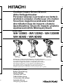 1
1
-
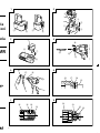 2
2
-
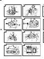 3
3
-
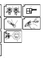 4
4
-
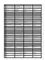 5
5
-
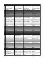 6
6
-
 7
7
-
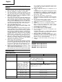 8
8
-
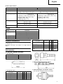 9
9
-
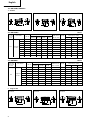 10
10
-
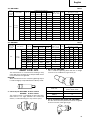 11
11
-
 12
12
-
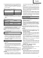 13
13
-
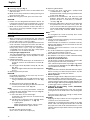 14
14
-
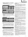 15
15
-
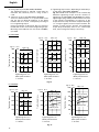 16
16
-
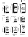 17
17
-
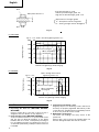 18
18
-
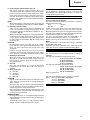 19
19
-
 20
20
-
 21
21
-
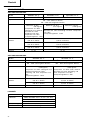 22
22
-
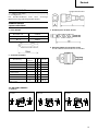 23
23
-
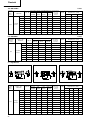 24
24
-
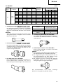 25
25
-
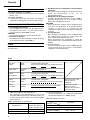 26
26
-
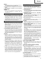 27
27
-
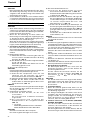 28
28
-
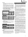 29
29
-
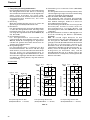 30
30
-
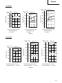 31
31
-
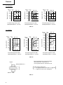 32
32
-
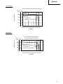 33
33
-
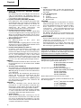 34
34
-
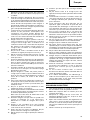 35
35
-
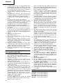 36
36
-
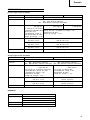 37
37
-
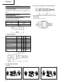 38
38
-
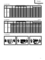 39
39
-
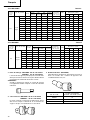 40
40
-
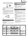 41
41
-
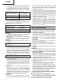 42
42
-
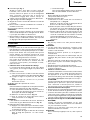 43
43
-
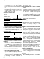 44
44
-
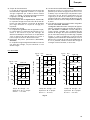 45
45
-
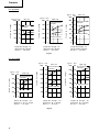 46
46
-
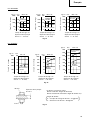 47
47
-
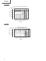 48
48
-
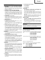 49
49
-
 50
50
-
 51
51
-
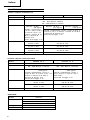 52
52
-
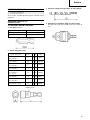 53
53
-
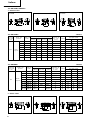 54
54
-
 55
55
-
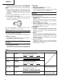 56
56
-
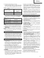 57
57
-
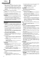 58
58
-
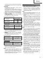 59
59
-
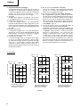 60
60
-
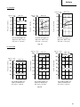 61
61
-
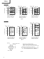 62
62
-
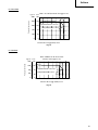 63
63
-
 64
64
-
 65
65
-
 66
66
-
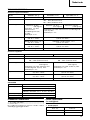 67
67
-
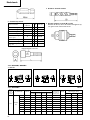 68
68
-
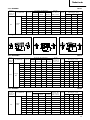 69
69
-
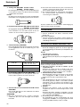 70
70
-
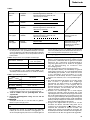 71
71
-
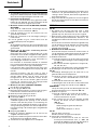 72
72
-
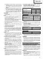 73
73
-
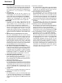 74
74
-
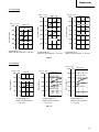 75
75
-
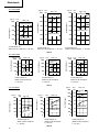 76
76
-
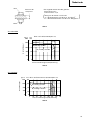 77
77
-
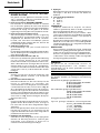 78
78
-
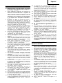 79
79
-
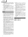 80
80
-
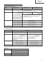 81
81
-
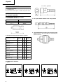 82
82
-
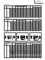 83
83
-
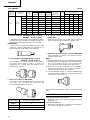 84
84
-
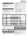 85
85
-
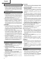 86
86
-
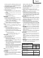 87
87
-
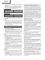 88
88
-
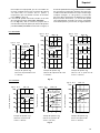 89
89
-
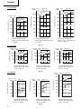 90
90
-
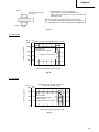 91
91
-
 92
92
-
 93
93
-
 94
94
-
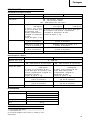 95
95
-
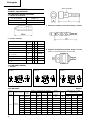 96
96
-
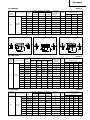 97
97
-
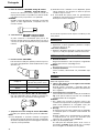 98
98
-
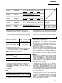 99
99
-
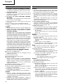 100
100
-
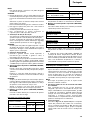 101
101
-
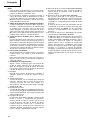 102
102
-
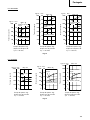 103
103
-
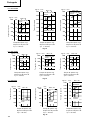 104
104
-
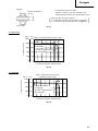 105
105
-
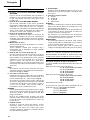 106
106
-
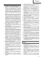 107
107
-
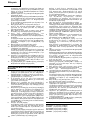 108
108
-
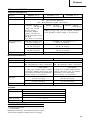 109
109
-
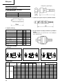 110
110
-
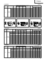 111
111
-
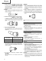 112
112
-
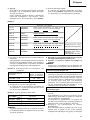 113
113
-
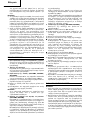 114
114
-
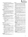 115
115
-
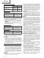 116
116
-
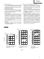 117
117
-
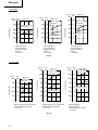 118
118
-
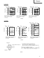 119
119
-
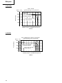 120
120
-
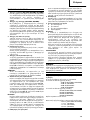 121
121
-
 122
122
-
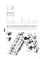 123
123
-
 124
124
-
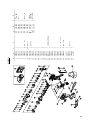 125
125
-
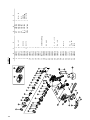 126
126
-
 127
127
-
 128
128
-
 129
129
-
 130
130


Hitachi WH 12DM2 Handling Instructions Manual
- Taper
- Handling Instructions Manual
dans d''autres langues
- italiano: Hitachi WH 12DM2
- English: Hitachi WH 12DM2
- español: Hitachi WH 12DM2
- Deutsch: Hitachi WH 12DM2
- Nederlands: Hitachi WH 12DM2
- português: Hitachi WH 12DM2
Documents connexes
-
Hitachi WH 12DM2 Manuel utilisateur
-
Hitachi WR 14DM Handling Instructions Manual
-
-
-
Hitachi WH14DM Manuel utilisateur
-
Hitachi WH12DMR Manuel utilisateur
-
Hitachi WR 9DM Manuel utilisateur
-
-
-