Samsung HW-J8500R Manuel utilisateur
- Catégorie
- Haut-parleurs de la barre de son
- Taper
- Manuel utilisateur

User manual
Imagine the possibilities
Thank you for purchasing this Samsung product.
To receive more complete service, please register your product at
www.samsung.com/register
HW-J8500R
HW-J8501R

2
GETTING STARTED
SAFETY INFORMATION
SAFETY WARNINGS
TO REDUCE THE RISK OF ELECTRIC SHOCK, DO NOT REMOVE THE COVER (OR BACK).
NO USER-SERVICEABLE PARTS ARE INSIDE. REFER SERVICING TO QUALIFIED SERVICE PERSONNEL.
CAUTION
RISK OF ELECTRIC SHOCK.
DO NOT OPEN.
This symbol indicates that high voltage is
present inside. It is dangerous to make any kind
of contact with any internal part of this product.
This symbol indicates that important literature
concerning operation and maintenance has
been included with this product.
Class II product : This symbol indicates that it does not require a safety connection to electrical earth
(ground).
AC voltage : This symbol indicates that the rated voltage marked with the symbol is AC voltage.
DC voltage : This symbol indicates that the rated voltage marked with the symbol is DC voltage.
Caution, Consult instructions for use : This symbol instructs the user to consult the user manual for further
safety related information.
WARNING
• To reduce the risk of fire or electric shock, do not expose this appliance to rain or moisture.
• To prevent injury, this apparatus must be securely attached to the floor/wall in accordance with the installation instructions.
CAUTION
• Do not expose this apparatus to dripping or splashing. Do not put objects filled with liquids, such as vases on the apparatus.
• To turn this apparatus off completely, you must pull the power plug out of the wall socket. Consequently, the power plug
must be easily and readily accessible at all times.
CAUTION (for Canada)
This equipment complies with Industry Canada licence-exempt RSS standard(s). Operation is subject to
the following two conditions: (1) this device may not cause interference, and (2) this device must accept any
interference, including interference that may cause undesired operation of the device.
This device and its antenna(s) must not be co-located or operation in conjunction with any other antenna or
transmitter.
This device may automatically discontinue transmission if there is no information to transmit, or an operational
failure. Note that this is not intended to prohibit the transmission of control or signaling information or the use of
repetitive codes where required by the technology.
This Class B digital apparatus complies with Canadian ICES-003.
FCC Radiation Exposure Statement
This equipment complies with IC RSS-102 radiation exposure limits set forth for an uncontrolled environment.
This equipment should be installed and operated with minimum distance 20cm between the radiator & your body.
GETTING STARTED

ENG
3
GETTING STARTED
Important Safety Instructions
Read these operating instructions carefully before using the unit.
Follow all the safety instructions listed below. Keep these
operating instructions handy for future reference.
1) Read these instructions.
2) Keep these Instructions.
3) Heed all warnings.
4) Follow all instructions.
5) Do not use this apparatus near water.
6) Clean only with a dry cloth.
7) Do not block any ventilation openings. Install in accordance
with the manufacturer's instructions.
8) Do not install near any heat sources such as radiators, heat
registers, stoves, or other apparatus (including amplifiers)
that produce heat.
9) Do not defeat the safety purpose of the polarized or
grounding-type plug. A polarized plug has two blades with
one wider than the other. A grounding type plug has two
blades and a third grounding prong. The wide blade or the
third prong are provided for your safety. If the provided plug
does not fit into your outlet, consult an electrician for
replacement of the obsolete outlet.
10) Protect the power cord from being walked on or pinched
particularly at plugs, convenience receptacles, and the point
where they exit from the apparatus.
11) Only use attachments/accessories specified by the
manufacturer.
12) Use only with the cart, stand, tripod,
bracket, or table specified by the
manufacturer, or sold with the apparatus.
When a cart is used, use caution when
moving the cart/apparatus combination to
avoid injury from tip-over.
13) Unplug this apparatus during lightning storms or when
unused for long periods of time.
14) Refer all servicing to qualified service personnel. Servicing is
required when the apparatus has been damaged in any
way, such as when the power-supply cord or plug is
damaged, liquid has been spilled or objects have fallen into
the apparatus, the apparatus has been exposed to rain or
moisture, does not operate normally, or has been dropped.
LICENSES
Manufactured under license from Dolby Laboratories.
Dolby, Dolby Audio and the double-D symbol are
trademarks of Dolby Laboratories.
For DTS patents, see http://patents.dts.com.
Manufactured under license from DTS Licensing Limited.
DTS, the Symbol, & DTS and the Symbol together are
registered trademarks, and DTS 2.0 Channel is a
trademark of DTS, Inc. © DTS, Inc. All Rights Reserved.
The terms HDMI and HDMI High-Definition Multimedia
Interface, and the HDMI Logo are trademarks or
registered trademarks of HDMI Licensing LLC in the
United States and other countries.

4
GETTING STARTED
WARNING: DO NOT INGEST BATTERY. CHEMICAL BURN HAZARD. The remote control supplied with
this product contains a coin/button cell battery. If the coin/button cell battery is swallowed, it can cause
severe internal burns in just 2 hours and can lead to death. Keep new and used batteries away from
children. If the battery compartment does not close securely, stop using the remote and make sure to
keep it away from children. If you think the battery might have been swallowed or placed inside any part of the body,
seek immediate medical attention.
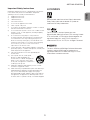
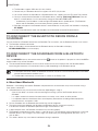
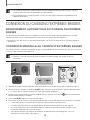
PRECAUTIONS
Ensure that the AC power supply in your house complies with the power requirements listed on the identification sticker
located on the back of your product. Install your product horizontally, on a suitable base (furniture), with enough space
around it for ventilation (3~4 inches). Make sure the ventilation slots are not covered. Do not place the unit on amplifiers
or other equipment which may become hot. This unit is designed for continuous use. To fully turn off the unit, disconnect
the AC plug from the wall outlet. Unplug the unit if you intend to leave it unused for a long period of time.
3.9 inch 3.9 inch
2.7 inch
3.9 inch
During thunderstorms, disconnect the AC plug from the
wall outlet. Voltage peaks due to lightning could damage
the unit.
Protect the product from moisture (i.e. vases), and
excess heat (e.g. a fireplace) or equipment creating
strong magnetic or electric fields. Unplug the power
cable from the AC wall socket if the unit malfunctions.
Your product is not intended for industrial use. It is for
personal use only. Condensation may occur if your
product has been stored in cold temperatures. If
transporting the unit during the winter, wait approximately
2 hours until the unit has reached room temperature
before using.
Do not expose the unit to direct sunlight or other heat
sources. This could lead to overheating and cause the
unit to malfunction.
The battery used with this product contains chemicals
that are harmful to the environment. Do not dispose of
the battery in the general household trash. Do not
expose the battery to excess heat, direct sunlight, or fire.
Do not short circuit, disassemble, or overheat the battery.
Danger of explosion if the battery is replaced incorrectly.
Replace only with the same or equivalent type.

ENG
5
GETTING STARTED
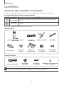
CONTENTS
2 GETTING STARTED
2 Safety Information
6 What’s Included
7 DESCRIPTIONS
7 Top / Front Panel
8 Rear / Bottom Panel
9 Remote Control
11 INSTALLATION
11 Installing the Soundbar
11 Installing the Wall Mount
15 Placing the Soundbar on a TV stand
16 Installing the Soundbar as a Free-Standing
Unit
17 Assembling the Clamp-Wire
17 Mounting the Cover-Feet
(4 EA) onto the Subwoofer
18 CONNECTIONS
18 Connecting the Subwoofer
20 Connecting to a TV
20 Connecting to a TV Using an HDMI (Digital)
Cable
20 Connecting to a TV Using a Digital Optical
Cable
21 TV SoundConnect
22 Connecting to External Devices
22 HDMI Cable
23 Optical or Analog Audio Cable
24 FUNCTIONS
24 Input Mode
25 Bluetooth
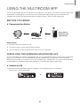
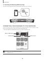
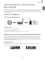
27 Using the Multiroom App
29 Using the Network Standby On
Function
30 Software Update
32 TROUBLESHOOTING
32 Troubleshooting
33 APPENDIX
33 Specifications
Figures and illustrations in this User Manual are
provided for reference only and may differ from actual
product appearance.

6
GETTING STARTED
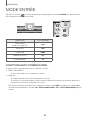
WHAT’S INCLUDED
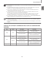
BEFORE READING THE USER’S MANUAL
Note the following terms before reading the user manual.
+ Icons used in this manual
Icon Term Definition
Caution
Indicates a situation where a function does not operate or settings may be canceled.
Note
Indicates tips or instructions on the page that help you operate a function.
Check for the supplied accessories shown below.
Main Unit
Remote Control /
Lithium Battery (3V : CR2032)
Power Cord AC/DC Adapter HDMI Cable
Clamp-Wire Holder-Fix Mount
Wall-Mount
Bracket
Holder-Screw 1
: 4 EA
Holder-Screw 2
: 4 EA
Subwoofer
Power Cord Cover-Foot : 4 EA Screw-Taptite : 4 EA Foot Rubber : 4 EA
● The appearance of the accessories may differ slightly from the illustrations above.

ENG
7
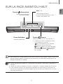
DESCRIPTIONS
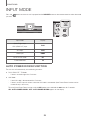
TOP / FRONT PANEL
(Power) Button
Turns the power on and off.
VOL. - / +
Controls the volume level.
The numeric value of the volume level
appears in the front panel display.
Display
Displays the current mode.
(Source) Button
Selects the D.IN, AUX, HDMI, BT, or TV input.
● While the unit is powered on, pressing the
button for more than 3 seconds sets
the button to act as the
(Mute) button.
To cancel the
(Mute) button setup,
press the
button for more than
3 seconds again.
● To clean this apparatus, unplug the power cord from the wall outlet and wipe the product using a soft, dry
cloth. Due to aluminum being a positive electrostatic material, static discharge may occur.
● When you plug in the AC cord, the power button will begin working in 4 to 6 seconds.
● When you turn on this unit, there will be a 4 to 5 second delay before it produces sound.
● If you want to enjoy sound only from the Soundbar, you must turn off the TV's speakers in the Audio Setup
menu of your TV. Refer to the owner's manual supplied with your TV.
DESCRIPTIONS

8
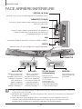
DESCRIPTIONS
REAR / BOTTOM PANEL
AUX IN
LAN HDMI IN
OPTICAL IN
HDMI OUT
(TV-ARC)
SERVICE
SPK ADDWi-Fi SETUP
DC 24V
SPK ADDWi-Fi SETUP
DC 24V
SERVICE
Wi-Fi SETUP
Press this button to
connect your Soundbar
to your network using
Wi-Fi setup. (Requires a
smart device and the
Samsung Multiroom app.
See page 27.)
SPK ADD
Press the button to connect
the Soundbar to a Samsung
HUB (purchased separately)
or a network. (Requires a
smart device and the
Samsung Multiroom app.
See page 27.)
DC 24V
(Power Supply In)
Connect the DC power
adaptor to the power supply
jack, and then connect the
AC power adaptor plug to a
wall outlet.
SERVICE
To upgrade the product's
software through the USB
Port.
OPTICAL IN (D.IN)
Connect to the digital (optical) output of an external device.
HDMI OUT (TV-ARC)
Outputs digital video and audio signals simultaneously using an
HDMI cable.
HDMI IN
Inputs digital video and audio signals simultaneously using an HDMI
cable. Use when connecting a supported external device.
AUX IN
Connect to the Analog output of an external device.
LAN
Lets you connect to a network using a LAN cable.
LABEL
● When disconnecting the power cable of the AC power adaptor from a wall outlet, pull the plug.
Do not pull the cable.
● Do not connect this unit or other components to an AC outlet until all connections between components
are complete.
● Make sure to rest the AC/DC Adapter flat on a table or the floor. If you place the AC/DC Adapter so that it
is hanging with the AC cord input facing upwards, water or other foreign substances could enter the
Adapter and cause the Adapter to malfunction.

ENG
9
DESCRIPTIONS
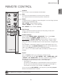
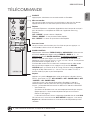
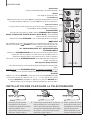
REMOTE CONTROL
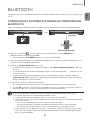
Anynet+
Press the Anynet+ button to turn the Anynet+ function on or off.
(Default : Auto Power Link OFF, ON - ANYNET+ / OFF - POWER LINK or OFF
- ANYNET+ / ON - POWER LINK). The Anynet+ function lets you control the
Soundbar with the remote from an Anynet+ compatible Samsung TV.
The Soundbar must be connected to the TV via an HDMI cable.
* Auto Power Link
Synchronizes the Soundbar to a connected Optical source via the Optical
jack so it turns on automatically when you turn on your TV. (See page 21)
Auto Power Link function is only available in the D.IN mode.
You can also activate Wi-Fi SETUP function by pressing and holding Anynet+
button on the remote for over 7 seconds.
Repeat
The Repeat function is available only when playing back music from Songs on phone
or DMS of Samsung Multiroom app.
OFF - REPEAT : Cancels Repeat Playback.
TRACK - REPEAT : Plays a track repeatedly.
ALL - REPEAT : Plays all tracks repeatedly.
Mute
You can turn the volume down to 0 with the push of a button.
Press again to restore the sound to the previous volume level.
SOURCE
Press to select a source connected to the Soundbar.
Skip Forward
If there is more than one file on the device you are playing, and you press
the
]
button, the next file is selected.
SOUND CONTROL
Press to select TREBLE, BASS or AUDIO SYNC. Then, use the
[
,
]
buttons to adjust the TREBLE or BASS volume from -3 ~ +3.
Press and hold the SOUND CONTROL button for about 5 seconds to adjust
the sound for each frequency band. 150Hz, 300Hz, 600Hz, 1.2KHz, 2.5KHz,
5KHz, and 10KHz are selectable and each can be adjusted to a setting between
-6 ~ +6.
If the Soundbar is connected to a digital TV and the video appears out of sync
with the audio, press the SOUND CONTROL button to sync the audio with the
video. Use the
[
,
]
buttons to set the audio delay between
0 ms ~ 300 ms. In TV mode, and BT mode, the Audio Sync function may not
available.
● Operate the TV using the TV's remote control.

10
DESCRIPTIONS
STREAMING MUSIC
Press STREAMING MUSIC button to listen to an Internet radio station. Each
time you press this button, the Soundbar switches to the next default station,
cycling through the 3 default stations.
To use the STREAMING MUSIC function, the Soundbar must be connected to
the Internet. (See page 29)
DRC (Dynamic Range Control) *
Lets you apply dynamic range control to Dolby Digital.
Press and hold the STREAMING MUSIC button to toggle the DRC (Dynamic
Range Control) function ON and OFF.
WOOFER
Press the WOOFER button. Then, use the
[
,
]
buttons to adjust the
Subwoofer volume from -12, -6
~
+6.
You can also activate SPK ADD function of the Soundbar by pressing and
holding WOOFER button of the remote for over 5 seconds.
SOUND
Surround Sound adds depth and spaciousness to the sound. Pressing the
SOUND button repeatedly cycles through the Surround Sound settings :
ON - SURROUND SOUND, OFF - SURROUND SOUND
Volume
Adjusts the volume level of the unit.
Power
Turns the Soundbar on and off.
SOUND EFFECT
You can select from 6 sound modes - STANDARD (Original Sound), MUSIC,
CLEAR VOICE, SPORTS, MOVIE, and NIGHT MODE - depending on the
content you want to listen to.
Select the STANDARD mode if you want to enjoy the original sound.
Play / Pause
Press the
p
button to pause a file temporarily.
Press the
p
button again to play the selected file.
Skip Back
If there is more than one file on the device you are playing, and you press the
[
button, the previous file is selected.
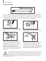
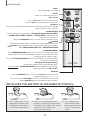
INSTALLING THE BATTERY IN THE REMOTE CONTROL
1. Use a suitable coin to turn the
remote control's battery cover
counterclockwise to remove it
as shown in the figure above.
2. Insert a 3V lithium battery. Keep the
positive (+) pole facing up when inserting
the battery. Put the battery cover on and
align the '●' marks side by side as
shown in the figure above.
3. Use a suitable coin to
turn the remote control
battery cover clockwise
as far as it will go to fix it
in place.

ENG
11
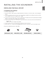
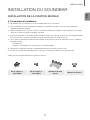
INSTALLATION
INSTALLING THE SOUNDBAR
INSTALLING THE WALL MOUNT
+ Installation Precautions
● Install on a vertical wall only.
● For the installation, avoid a location with high temperature or humidity, or a wall that cannot sustain the weight of
the set.
● Check the strength of the wall. If the wall is not strong enough to support the unit, reinforce the wall or install the
unit on a different wall that can support the unit's weight.
● Purchase and use the fixing screws or anchors appropriate for the kind of wall you have (plaster board, iron board,
wood, etc.). If possible, fix the support screws into wall studs.
● Purchase wall mounting screws according to the type and thickness of the wall you will mount the Soundbar on.
- Diameter : M5
- Length: 1 3/8 inches or longer recommended.
● Connect cables from the unit to external devices before you install it on the wall.
● Make sure the unit is turned off and unplugged before you install it. Otherwise, it may cause an electric shock.
Check for the supplied accessories shown below.
Holder-Screw 1 : 4 EA Holder-Screw 2 : 4 EA Wall-Mount Bracket Holder-Fix Mount
INSTALLATION

12
INSTALLATION
AUX IN
LAN HDMI IN
OPTICAL IN
HDMI OUT
(TV-ARC)
SERVICE
SPK ADDWi-Fi SETUP
DC 24V
AUX IN
LAN HDMI IN
OPTICAL IN
HDMI OUT
(TV-ARC)
SERVICE
SPK ADDWi-Fi SETUP
DC 24V
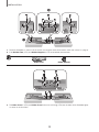
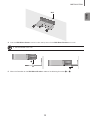
1
2
1. Place the Soundbar as shown in the illustration, ensuring that none of the buttons touch the surface it is lying on.
2. If the Holder-Foot (3 EA) and Holder-Support (2 EA) are attached, remove them.
Holder-Foot Holder-Support
AUX IN
LAN HDMI IN
OPTICAL IN
HDMI OUT
(TV-ARC)
SERVICE
SPK ADDWi-Fi SETUP
DC 24V
AUX IN
LAN HDMI IN
OPTICAL IN
HDMI OUT
(TV-ARC)
SERVICE
SPK ADDWi-Fi SETUP
DC 24V
3. Fix Holder-Screw 1 (4 EA) and Holder-Screw 2 (for main unit fixing) (4 EA) into the holes of the Soundbar tightly
as shown in the illustration.

ENG
13
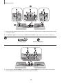
INSTALLATION
Wall
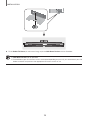
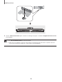
4. Insert the Wall-Mount Screws into the 3 holes one by one to fix the Wall-Mount Bracket on the wall.
● Recommended screw : M5
1
2
5. Mount the Soundbar on the Wall-Mount Bracket in order of the following illustration (1 2).

14
INSTALLATION
6. Fix the Holder-Fix Mount (for wall-mount fixing) to join the Wall-Mount Bracket with the Soundbar.
● Wall-Mount Screws are not provided.
● Since different types of wall-mount screws are required depending on your wall, you should check your wall
before installation and purchase the appropriate wall-mount screws to use.

ENG
15
INSTALLATION
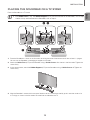
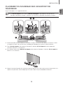
PLACING THE SOUNDBAR ON A TV STAND
Place the Soundbar on a TV stand.
● If the Holder-Foot (3 EA) and Holder-Support (2 EA) are not attached to the Soundbar, start at Step
1 below. If they are attached to the Soundbar, start at Step 4.
AUX IN
LAN HDMI IN
OPTICAL IN
HDMI OUT
(TV-ARC)
5V 0.5A
SPK ADDWi-Fi SETUP
DC 24V
AUX IN
LAN HDMI IN
OPTICAL IN
HDMI OUT
(TV-ARC)
5V 0.5A
SPK ADDWi-Fi SETUP
DC 24V
2 3
1
1. Place the Soundbar as shown in the illustration, ensuring that none of the buttons touch the surface it is lying on.
You can use the Soundbar's packaging to support its two ends.
2. Attach the Holder-Foot (3 EA) to the Soundbar using 3 Holder-Screws 2 as shown in the illustration. Tighten the
screws firmly.
3. In the same manner, attach the Holder-Support (2 EA) to the Soundbar using 2 Holder-Screws 2. Tighten the
screws firmly.
4. Align the Soundbar’s center with the center of the base of the TV, and then carefully push it onto the stand as far
as it will go, as shown in the illustration. Be careful not to unbalance the TV.

16
INSTALLATION
● Do not place heavy items on the main unit. Do not step on the main unit.
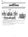
INSTALLING THE SOUNDBAR AS A FREE-STANDING UNIT
AUX IN
LAN HDMI IN
OPTICAL IN
HDMI OUT
(TV-ARC)
SERVICE
SPK ADDWi-Fi SETUP
DC 24V
AUX IN
LAN HDMI IN
OPTICAL IN
HDMI OUT
(TV-ARC)
SERVICE
SPK ADDWi-Fi SETUP
DC 24V
2 3
1
4
1. If the Holder-Foot and the Holder-Support are attached to the Soundbar, place the Soundbar as shown in the
illustration, ensuring that none of the buttons touch the surface it is lying on. You can use the Soundbar's
packaging to support its two ends.
2. Remove the Holder-Foot (3 EA) and the 3 Holder-Screws 2 holding the pieces of the Holder-Foot in place from
the Soundbar as shown in the illustration.
3. In the same manner, remove the Holder-Support (2 EA) and the 2 Holder-Screws 2 holding the pieces of the
Holder-Support in place from the Soundbar.
4. Place the Soundbar anywhere you want.

ENG
17
INSTALLATION
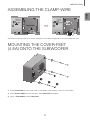
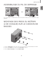
ASSEMBLING THE CLAMP-WIRE
AUX IN
LAN
HDMI IN OPTICAL IN
HDMI OUT
(TV-ARC)
AUX IN
LAN
HDMI IN OPTICAL IN
HDMI OUT
(TV-ARC)
AUX IN
LAN
HDMI IN OPTICAL IN
HDMI OUT
(TV-ARC)
AUX IN
LAN
HDMI IN OPTICAL IN
HDMI OUT
(TV-ARC)
Clamp-Wire
Attach the clamp-wire to the unit as shown, and then run the cables through the clamp-wire to keep them neat.
MOUNTING THE COVER-FEET
(4 EA) ONTO THE SUBWOOFER
POWER
1
2
3
1. Place a Cover-Foot on each of the 4 holes in the bottom of the woofer as shown in the illustration.
2. Insert a Screw-Taptite into each the hole in each Cover-Foot and tighten.
3. Attach a Foot Rubber to each Cover-Foot.

18
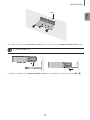
CONNECTIONS
● Do not connect the power cord of this product or your TV to a wall outlet until all connections between
components are complete.
● Before moving or installing this product, be sure to turn off the power and disconnect the power cord.
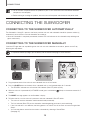
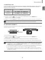
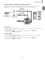
CONNECTING THE SUBWOOFER
CONNECTING TO THE SUBWOOFER AUTOMATICALLY
The Subwoofer's linking ID is preset at the factory and the main unit and subwoofer should link (connect wirelessly)
automatically when the main unit and subwoofer are turned on.
• When the subwoofer is completely connected, the blue LED Link Indicator on the subwoofer stops blinking and
glows continuously.
CONNECTING TO THE SUBWOOFER MANUALLY
If the blue LED light does not stop blinking when the main unit and subwoofer are turned on, please set the ID by
following the steps below.
● Important: Before you begin, put the battery into the remote. See page 10 for instructions.
POWER
1. Plug the power cords of the main unit and subwoofer into an AC wall outlet.
2. Press the ID SET button on the back of the subwoofer with a small, pointed object for 5 seconds.
• The STANDBY indicator turns off and the LINK indicator (Blue LED) blinks quickly.
3. While the main unit is powered off (in STANDBY mode), press and hold the (Mute) on the remote control for 5
seconds.
4. The ID SET message appears on the Soundbar's display.
5. To finalize the link, turn the main unit’s power on while the subwoofer’s Blue LED blinks.
• The main unit and the subwoofer should now be linked (connected).
• The Link indicator (Blue LED) on the subwoofer should be glowing continuously and not blinking.
• If the Link indicator is not solid blue, the linking process has failed. Turn off the main unit and start again from
Step 2.
• You can enjoy better sound from the wireless subwoofer by selecting a Sound Effect.
(See page 10)
CONNECTIONS

ENG
19
CONNECTIONS
● Before moving or installing the product, be sure to turn off the power and disconnect the power cord.
● If the main unit is powered off, the wireless subwoofer will in standy mode and the STANDBY LED on the
top will blink Red directly. (no blue LED).
● If you use a device that uses the same frequency (2.4GHz) as the Soundbar near the Soundbar,
interference may cause some sound interruption.
● The maximum transmission distance of the wireless signal between the main unit and subwoofer is about
32.8 ft, but may vary depending on your operating environment. If a steel-concrete or metallic wall is
between the main unit and the wireless subwoofer, the system may not operate at all, because the wireless
signal cannot penetrate metal.
● If the main unit doesn't make a wireless connection, follow steps 1-5 on the previous page to re-set the
connection between the main unit and wireless subwoofer.
● The wireless receiving antenna is built into the wireless subwoofer. Keep the unit away from water and
moisture.
● For optimal listening performance, make sure that the area around the wireless subwoofer location is clear
of any obstructions.
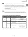
LED INDICATOR LAMP STATUS ON SUBWOOFER
LED Status Description Resolution
Red On
Standby (with the Soundbar main
unit turned off)
Check the power supply to the
Soundbar main unit
Connection failed
Connect again
(refer to the instructions on manual
connection in the user manual)
Blue
On
Successfully connected
(normal operation)
-
Blinking
Standby (with the Soundbar main
unit turned off)
Check the power supply to the
Soundbar main unit
Connection failed
Connect again
(refer to the instructions on manual
connection in the user manual)
Red and blue Blinking Malfunction Contact the service center.

20
CONNECTIONS
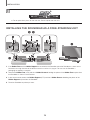
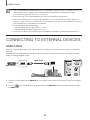
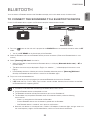
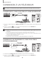
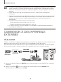
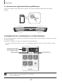
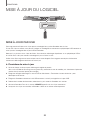
CONNECTING TO A TV
● Important: Before you begin, put the battery into the remote. See page 10 for instructions.
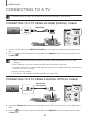
CONNECTING TO A TV USING AN HDMI (DIGITAL) CABLE
AUX IN
LAN HDMI IN
OPTICAL IN
HDMI OUT
(TV-ARC)
SERVICE
SPK ADDWi-Fi SETUP
DC 24V
HDMI IN
HDMI OUT
(TV-ARC)
HDMI Cable
1. Connect an HDMI cable from the HDMI OUT (TV-ARC) jack on the back of the product to the HDMI IN jack on
your TV.
2. Press the button on the top panel of the Soundbar or the SOURCE button on the remote control to select
the D.IN mode.
● HDMI is an interface that enables the digital transmission of video and audio data with just a single
connector.
● If the TV provides an ARC port, connect the HDMI cable to the HDMI IN (ARC) port.
● We recommend you use a coreless HDMI cable if possible. If you use a cored HDMI cable, use one whose
diameter is less than 0.55 inches.
● Anynet+ must be turned on.
● This function is not available if the HDMI cable does not support ARC.
CONNECTING TO A TV USING A DIGITAL OPTICAL CABLE
AUX IN
LAN HDMI IN
OPTICAL IN
HDMI OUT
(TV-ARC)
SERVICE
SPK ADDWi-Fi SETUP
DC 24V
OPTICAL IN
OPTICAL OUT
Optical Cable
(not supplied)
1. Connect the OPTICAL IN (Audio) jack on the Soundbar to the OPTICAL OUT jack of the TV with a digital optical
cable.
2. Press the button on the top panel of the Soundbar or the SOURCE button on the remote control to select
the D.IN mode.
La page est en cours de chargement...
La page est en cours de chargement...
La page est en cours de chargement...
La page est en cours de chargement...
La page est en cours de chargement...
La page est en cours de chargement...
La page est en cours de chargement...
La page est en cours de chargement...
La page est en cours de chargement...
La page est en cours de chargement...
La page est en cours de chargement...
La page est en cours de chargement...
La page est en cours de chargement...
La page est en cours de chargement...
La page est en cours de chargement...
La page est en cours de chargement...
La page est en cours de chargement...
La page est en cours de chargement...
La page est en cours de chargement...
La page est en cours de chargement...
La page est en cours de chargement...
La page est en cours de chargement...
La page est en cours de chargement...
La page est en cours de chargement...
La page est en cours de chargement...
La page est en cours de chargement...
La page est en cours de chargement...
La page est en cours de chargement...
La page est en cours de chargement...
La page est en cours de chargement...
La page est en cours de chargement...
La page est en cours de chargement...
La page est en cours de chargement...
La page est en cours de chargement...
La page est en cours de chargement...
La page est en cours de chargement...
La page est en cours de chargement...
La page est en cours de chargement...
La page est en cours de chargement...
La page est en cours de chargement...
La page est en cours de chargement...
La page est en cours de chargement...
La page est en cours de chargement...
La page est en cours de chargement...
La page est en cours de chargement...
La page est en cours de chargement...
La page est en cours de chargement...
La page est en cours de chargement...
La page est en cours de chargement...
La page est en cours de chargement...
-
 1
1
-
 2
2
-
 3
3
-
 4
4
-
 5
5
-
 6
6
-
 7
7
-
 8
8
-
 9
9
-
 10
10
-
 11
11
-
 12
12
-
 13
13
-
 14
14
-
 15
15
-
 16
16
-
 17
17
-
 18
18
-
 19
19
-
 20
20
-
 21
21
-
 22
22
-
 23
23
-
 24
24
-
 25
25
-
 26
26
-
 27
27
-
 28
28
-
 29
29
-
 30
30
-
 31
31
-
 32
32
-
 33
33
-
 34
34
-
 35
35
-
 36
36
-
 37
37
-
 38
38
-
 39
39
-
 40
40
-
 41
41
-
 42
42
-
 43
43
-
 44
44
-
 45
45
-
 46
46
-
 47
47
-
 48
48
-
 49
49
-
 50
50
-
 51
51
-
 52
52
-
 53
53
-
 54
54
-
 55
55
-
 56
56
-
 57
57
-
 58
58
-
 59
59
-
 60
60
-
 61
61
-
 62
62
-
 63
63
-
 64
64
-
 65
65
-
 66
66
-
 67
67
-
 68
68
-
 69
69
-
 70
70


Samsung HW-J8500R Manuel utilisateur
- Catégorie
- Haut-parleurs de la barre de son
- Taper
- Manuel utilisateur
dans d''autres langues
- English: Samsung HW-J8500R User manual
Documents connexes
-
Samsung HW-J250 Guide de démarrage rapide
-
Samsung HW-J7500R Manuel utilisateur
-
Samsung HW-J7500 Manuel utilisateur
-
Samsung HW-H355 Manuel utilisateur
-
-
Samsung HW-H355/XN Manuel utilisateur
-
-
Samsung HW-J6011 Manuel utilisateur
-
Samsung HW-K430 Guide de démarrage rapide
-
Samsung HW-J7501R Manuel utilisateur