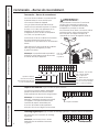
GE AZ75H09DAC Owner's Manual and Installation Instructions
- Catégorie
- Climatiseurs split-system
- Taper
- Owner's Manual and Installation Instructions
Ce manuel convient également à

TINSEA517JBRZ 49-7594-1 10-08 JR
Air Conditioners
Safety Instructions . . . . . . . . . . .2
Operating Instructions
Controls—Dip Switches . . . . . . . . .3–5
Controls—Terminal
Connections . . . . . . . . . . . . . . . . . . .6, 7
On/Off Switch . . . . . . . . . . . . . . . . . . . .8
Ventilation Control . . . . . . . . . . . . . . . .8
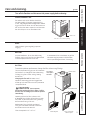
Care and Cleaning
Air Filters . . . . . . . . . . . . . . . . . . . . . . . . .9
Base Pan . . . . . . . . . . . . . . . . . . . . . . . . .9
Exhaust Coils . . . . . . . . . . . . . . . . . . . . .9
Installation Instructions
Electrical Supply . . . . . . . . . . . . .11–13
Installing the Zoneline . . . . . . .14–21
Preparation . . . . . . . . . . . . . . . . . . . . .10
Servicing . . . . . . . . . . . . . . . . . . . . . . . .22
Troubleshooting Tips . . . . . . .23
Normal Operating Sounds . . . . . . .24
Consumer Support
Consumer Support . . . . . .Back Cover
Warranty . . . . . . . . . . . . . . . . . . . . . . .27
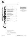
Cool Only, Heat/Cool and
Heat Pump Models
7500 Series
Owner’s Manual and
Installation Instructions
ge.com
Write the model and serial
numbers here:
Model # __________________
Serial # __________________
Find these numbers on a label
on the front case panel.
Zoneline
®
Vertical
Printed in China

Consumer Support Troubleshooting Tips Care and Cleaning Operating Instructions Safety Instructions
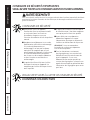
IMPORTANT SAFETY INFORMATION.
READ ALL INSTRUCTIONS BEFORE USING.
WARNING!
For your safety, the information in this manual must be followed to minimize the risk of fire, electric
shock, or to prevent property damage, personal injury, or loss of life.
■ This Zoneline must be properly installed
in accordance with the Installation
Instructions before it is used.
See the Installation Instructions
in the back of this manual.
■ Replace immediately all electric service
cords that have become frayed or
otherwise damaged. A damaged power
supply cord must be replaced with
a new power supply cord obtained
from the manufacturer and not repaired.
Do not use a cord that shows cracks
or abrasion damage along its length
or at either the plug or connector end.
■ Product must be operated with
the electrical plug supplied with the
product. Do not replace the electrical
plug supplied with the product.
■ If the receptacle does not match the plug,
the receptacle must be changed out by
a qualified electrician.
■ Unplug or disconnect the Zoneline
at the fuse box or circuit breaker before
making any repairs.
NOTE: We strongly recommend that
any servicing be performed by a qualified
individual.
■ All air conditioners contain refrigerants,
which under federal law must be
removed prior to product disposal.
If you are getting rid of an old product
with refrigerants, check with the
company handling disposal about
what to do.
SAFETY PRECAUTIONS
READ AND FOLLOW THIS SAFETY INFORMATION CAREFULLY.
SAVE THESE INSTRUCTIONS
2

Safety Instructions Operating Instructions Care and Cleaning Troubleshooting Tips Consumer Support
3
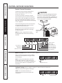
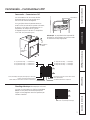
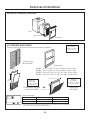
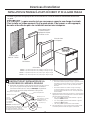
Controls–dip switches. ge.com
The dip switch controls are located behind
the front case panel, through an opening
on the front of the unit.
To access the dip switches, remove the front
case panel by removing the filter, taking out
the four front screws, the upper two screws from
the top of the panel and the shipping screws on
each side, if present. (Discard the two side shipping
screws, if present).
NOTE: The owner is responsible for setting
the appropriate dip switches and connecting
terminals.
Controls–Dip Switches
Dip
Switches
All Electric Heat (Heat pump models only)
When this switch is enabled (UP), heat pump
operation is locked out, causing the unit to provide
only electric resistance heat.
ALL I
2
R (All Electric Heat)
ALL I
2
R (All Electric Heat) (Heat-pump models only)
FREEZ S (Freeze Sentinel)
CONST FAN (Constant ON Fan)
TL1 (H) (Temp. Limit 1–Heat)
TL2 (H) (Temp. Limit 2–Heat)
TL3 (H) (Temp. Limit 3–Heat)
TL1 (C) (Temp. Limit 1–Cool)
TL2 (C) (Temp. Limit 2–Cool)
TL3 (C) (Temp. Limit 3–Cool)
No Function (Reserved for future use)
DUCT (Blower Fan)
OCCUPIED (Occupancy Sensor)
Side
shipping
screw
Side
shipping
screw

Consumer Support Troubleshooting Tips Care and Cleaning Operating Instructions Safety Instructions
4
Controls–dip switches.
Freeze Sentinel (Requires room air sensor kit–RAVRMS)
When this switch is enabled (UP), it turns OFF
the freeze sentinel protection feature. With the
switch disabled (DOWN), the freeze sentinel is
activated which automatically provides heat
without user interface. This helps to prevent
plumbing damage by turning the heater
and fans ON at 41° F and OFF at 46° F.
Constant ON Fan
When this switch is enabled (UP), it allows the fan
to run continuously.
Occupancy Sensor
When this switch is enabled (UP), it allows the unit
to utilize an infrared motion sensor and a door
switch for occupancy detection. This feature
allows an energy management system
to be installed and operated in conjunction
with the unit.
FREEZE S (Freeze Sentinel)
CONST FAN (Constant
ON Fan)
OCCUPIED
(Occupancy Sensor)
Duct
The duct select function allows the indoor
fan to be operated at two variable fan speeds.
When this switch is enabled (UP), the unit
automatically selects either high or middle fan
speed (for longer ductwork applications). When set
in the down position, the unit is automatically
operated in either the middle or low fan speed
(for shorter ductwork applications).
DUCT
(Blower Fan)

5
Safety Instructions Operating Instructions Care and Cleaning Troubleshooting Tips Consumer Support
ge.com
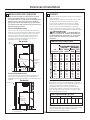
Temperature Limiting (Requires room air sensor kit–RAVRMS)
Temperature limiting can reduce energy costs
by limiting the lowest temperature that can be
set for cooling and the highest temperature that
can be set for heating. Temperature limiting is
controlled by switches 1–6 on the top block
of auxiliary controls. The first three switches are
used to select the cooling limits. The next three
switches are used to control the heating limits.
Temperature limiting during COOL mode
(all temperatures shown in °F)
UP DOWN Minimum Maximum
NONE 1, 2, 3 60° 85°
1 2, 3 64° 85°
1, 2 3 66° 85°
2 1, 3 68° 85°
2,3 1 70° 85°
1, 2, 3 NONE 72° 85°
1, 3 2 74° 85°
3 1, 2 76° 85°
Temperature limiting during HEAT mode
(all temperatures shown in °F)*
UP DOWN Minimum Maximum
NONE 4, 5, 6 60° 85°
4 5, 6 60° 80°
4, 5 6 60° 78°
5 4, 6 60° 76°
5,6 4 60° 74°
4, 5, 6 NONE 60° 72°
4, 6 5 60° 70°
6 4, 5 60° 65°
TL1 (C) (Temp. Limit 1–Cool)
TL2 (C) (Temp. Limit 2–Cool)
TL3 (C) (Temp. Limit 3–Cool)
TL1 (H) (Temp. Limit 1–Heat)*
TL2 (H) (Temp. Limit 2–Heat)*
TL3 (H) (Temp. Limit 3–Heat)*
* Not applicable to Cool-Only models

6
Consumer Support Troubleshooting Tips Care and Cleaning Operating Instructions Safety Instructions
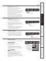
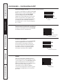
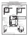
Controls—terminal connections.
Controls–Terminal Connections
The terminal connections are located behind
the front case panel through an opening
on the front of the unit.
To access the terminal connections, remove
the front panel by removing the filter, taking out
the four front screws, the upper two screws from
the top of the panel and the shipping screws on
each side, if present. (Discard the two side shipping
screws, if present.)
Insert the building hook-up wires into the bottom
of the terminals and tighten screws securely
to make the desired connections.
Route the wires from the terminal connections
through the unit wire guides and out through
the case wire guide.
NOTE: The owner is responsible for setting
the appropriate dip switches and connecting
terminals.
CAUTION:
Improper CDC wiring may damage the Zoneline
electronics or cause erratic Zoneline operation.
No common busing is permitted. A separate wire
pair must be run from each separate controlling
switch to each individual Zoneline.
Room Air Sensor (Requires room air sensor kit – RAVRMS)
When connected, the room air sensor will allow
utilization of the temperature limiting and freeze
sentinel features.
NOTE: If GE thermostat RAK148D1, RAK148P1
or RAK164D1, RAK164P1 is used with the unit,
the room sensor kit is not needed for temperature
limiting since this feature is incorporated in the
thermostats.
Route wires
through wire
guides
Room Air Sensor
Motion Sensor
Door Sensor
Central Desk Control
Common–Ground
White–Heater
Yellow–Compressor
Black–Reversing Valve
Green–High Speed Fan
Green–Low Speed Fan
Red–24V AC only
Room Air Sensor
Terminal
connections
Hydronic Heating (Requires Hydronic Heating Kit – RAVHW1, RAVHW2 or RAVHW3)
Required connections for hydronic heating kit.
NOTE: R, W, C terminal connections will
also be connected to the remote thermostat
if applicable.
Hydronic Heating

Remote Thermostat
The unit will be controlled by a remote thermostat.
IMPORTANT:
The Zoneline thermostat connections
provide 24V AC only.
If using a digital/electronic wall thermostat,
you must set it to the 24V AC setting. See the
Installation Instructions for the wall thermostat.
CAUTION:
Damage to a wall thermostat or to the
Zoneline electronics can result from improper
connections. Exercise extra attention when
connecting blue and black wires. No line
voltage connections should be made to any circuit
in the thermostat. Isolate all wires in building from
line voltage.
7
Safety Instructions Operating Instructions Care and Cleaning Troubleshooting Tips Consumer Support
ge.com
Door Sensor (Obtained locally)
The Occupancy Sensor dip switch must be
in the up position to use this feature.
When connected, the door sensor will detect
when the door in the room is opened or closed.
This feature must be used in conjunction with
the motion sensor.
The door and motion sensors work together
to automatically cycle the unit between normal
and energy management operations.
Central Desk Control
When connected, the unit lock-out is released
and it can be turned ON or OFF with a switch
located at the Central Desk Control. A separate
wire pair must be run from each separate
controlling switch to each individual Zoneline.
Motion Sensor (Obtained locally)
The Occupancy Sensor dip switch must be in
the up position to use this feature.
When connected, the wall mounted motion sensor
will detect motion in the room and automatically
cycle the unit between normal operation and
energy management operation.
The door and motion sensors work together
to automatically cycle the unit between normal
operation and energy management operation.
Motion Sensor
Door Sensor
Central Desk Control
Red–24V AC only
Green–Low Speed Fan
Green–High Speed Fan
Black–Reversing Valve
Yellow–Compressor
White–Heater
Common–Ground

The ventilation control lever is located on the left
side of the Zoneline unit, behind the front case
panel.
To access the ventilation control lever, remove
the front panel by removing the filter, taking out
the four front screws, the upper two screws from
the top of the panel and the shipping screws on
each side, if present. (Discard the two side shipping
screws, if present).
When the lever is in the CLOSE position, only the air
inside the room is circulated and filtered.
When the lever is in the OPEN position, some
outdoor air will be drawn into the room. This
will reduce the heating or cooling efficiency.
To close the vent, push the vent lever handle
down, pull it forward and lock it up in place.
To open the vent, push the vent lever handle
down, push it back and lock it up in place.
Energy Tip: Keep the vent control in the CLOSE
position. The room air will be filtered and circulated.
8
Consumer Support Troubleshooting Tips Care and Cleaning
Operating Instructions Safety Instructions
Other features of your Zoneline.
About Heat Pumps (on some models)
Heat pumps can reduce operating costs by
exchanging heat from the outside air—even
when the outside temperature is below freezing—
and releasing that heat indoors.
To get the best economic benefit from your heat
pump, don’t change the room thermostat setting
very often. Raising the heat setting 2–3 degrees
will cause the Zoneline to use its electric heating
elements in order to reach the new temperature
setting quickly.
There is a three minute minimum compressor run
time at any setting to prevent short cycling.
The indoor fan motor starts before the compressor
and stops after the compressor cycles off.
The electric heating elements use much
more electricity than heat pumps and cost
more to operate.
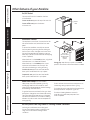
Ventilation Control
Vent control
(push lever down
and pull forward
or back to
operate)
Open
Close
On/Off Switch
The unit on/off switch is located on the front
of the Zoneline.
To turn on the unit, press the top of the switch in.
To turn off the unit, press the bottom
of the switch in.
ON/OFF
switch
Do Not Operate Cool-Only Models in Freezing Outdoor Conditions
Cool-only air conditioners are not designed
for use when freezing outdoor conditions exist.
They must not be used in freezing outdoor
conditions.

Indoor/Outdoor Coils
The exhaust coils on the Zoneline should be
checked regularly. If they are clogged with dirt
or soot, they may be professionally steam cleaned
by your GE service center. You will need to remove
the unit from the case to inspect the coils because
the dirt build-up occurs on the exhaust side.
9
Safety Instructions
Operating Instructions Care and Cleaning Troubleshooting Tips Consumer Support
Care and cleaning. ge.com
Base Pan
In some installations, dirt or other debris may
be blown into the unit from the outside and settle
in the base pan (the bottom of the unit).
In some areas of the United States, a “gel-like”
substance may be present in the base pan.
Check it periodically and clean, if necessary.
Turn off the Zoneline and disconnect the power supply before cleaning.
Outdoor coils
To maintain optimum performance, change the filter at least every 30 days.
Air Filters
The most important thing you can do to maintain
the Zoneline is to change the filter at least every
30 days. Dirty filters reduce cooling, heating
and air flow.
Changing the filter will: Decrease cost of
operation, save energy, prevent clogged heat
exchanger coils and reduce the risk of premature
component failure.
CAUTION: Do not operate
the Zoneline without the filter in place. If a filter
becomes torn or damaged, it should be replaced
immediately.
Operating without the filter in place or with
a damaged filter will allow dirt and dust to reach
the indoor coil and reduce the cooling, heating,
airflow and efficiency of the unit.
Replacement filters should be purchased
from your local retailer where air conditioner
and furnace accessories are sold.
Filter size required is 20″ x 20″ x 1″.
Have the coils cleaned regularly.
Unit-mounted filter
Remove filter
Access-panel with
return air grille
Return air grille
Filter
Filter
To remove
and replace
the filter:
Drain
Clean the drain system regularly to prevent
clogging.

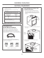
BEFORE YOU BEGIN
Installation Zoneline Air
Instructions Conditioners
Read these instructions completely and carefully.
•
IMPORTANT
–
Save these instructions
for local inspector’s use.
•
IMPORTANT
–
Observe all governing
codes and ordinances.
• Note to Installer – Be sure to leave these
instructions with the owner.
• Note to Owner – Keep these instructions
for future reference.
• Proper installation is the responsibility of the installer.
• Product failure due to improper installation is not
covered under the Warranty.
• You MUST use all supplied parts and use proper
installation procedures as described in these
instructions when installing this air conditioner.
Questions? Visit our Website at: ge.com or call 800.GE.CARES (800.432.2737).
IMPORTANT ELECTRICAL
SAFETY–READ CAREFULLY
CAUTION:
• All electrical connections and wiring MUST
be installed by a qualified electrician.
• Follow the National Electrical Code (NEC)
and/or local codes and ordinances.
• For personal safety, this Zoneline unit and case
must be properly grounded.
• Protective devices (fuses or circuit breakers)
acceptable for Zoneline installations are specified
on the nameplate of each unit.
• Do not use an extension cord with this unit.
• Aluminum building wiring may present special
problems—consult a qualified electrician.
• When the unit is not running there is still voltage
to the electrical controls.
• Disconnect the power to the unit before
servicing by:
1. Removing the power cord (if it has one) from
the wall receptacle.
OR
2. Removing the branch circuit fuses or turning
the circuit breakers off at the panel.
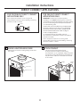
Phillips screwdriver
TOOLS YOU WILL NEED
10
WARNING:
Before beginning the
installation, switch power off at the service panel
and lock the area to prevent power from being
switched on accidentally. When the area cannot
be locked, securely fasten a prominent warning
device, such as a tag, to the service panel.
Adjustable wrench
Saw
Hammer
Tape measure

11
Installation Instructions
ELECTRICAL REQUIREMENTS
230/208 VOLT
ELECTRICAL SUPPLY
Tandem
15 Amp
230/208 volt receptacle configuration
Perpendicular
20 Amp
Large Tandem
30 Amp
• Use ONLY the wiring size recommended for single
outlet branch circuit.
• Proper current protection is the responsibility
of the owner.
A power supply kit must be used to supply power
to the Zoneline unit. The appropriate kit is determined
by the voltage, the means of electrical connection
and the amperage of the branch circuit. See the POWER
CONNECTION CHART on page 13 to select the appropriate kit.
All wiring, including installation of the receptacle,
must be in accordance with the NEC and local codes,
ordinances and regulations.
Power supply kit
Recommended branch circuit wire sizes*
Nameplate
maximum circuit AWG Wire
breaker size size**
15A 14
20A 12
30A 10
AWG – American Wire Gauge
* Single circuit breaker from main box
** Based on copper wire, single insulated conductor at 60° C
NOTE: Use copper conductors only.
FOR 230/208 VOLT POWER CORD
CONNECTIONS ONLY
1. Remove the front panel by taking out the four
front screws, the upper two screws from the top
of the panel and the shipping screws on each side,
if present. (Discard the two side shipping screws,
if present.)
2. Remove the junction box cover and the junction box
and discard.
3. Connect the power cord, with a loop, through
the strain relief.
Strain relief
IMPORTANT:
Power cord must
have a loop.
Remove
junction box
and cover
Side
shipping
screw
Side
shipping
screw

REMOVE JUNCTION BOX COVER
• Remove the junction box cover by taking out the front
two screws.
1
Junction box
Installation Instructions
12
DIRECT CONNECT APPLICATIONS
FOR 265 VOLT DIRECT CONNECT
APPLICATIONS ONLY
IMPORTANT: Connection of a 265V AC product
to a branch circuit MUST be done by direct connection
in accordance with the National Electrical Code. Plugging
this unit into a building mounted exposed receptacle
is not permitted by code.
These models must be installed using the appropriate
GE power supply kit for the branch circuit amperage
and the electrical resistance heater wattage desired.
See the POWER CONNECTION CHART on page 13
to select the appropriate kit.
It is the responsibility of the installer to ensure
the connection of components is done in accordance
with electrical codes.
Direct connection to branch circuit wiring inside
the provided junction box must be made by connecting
as follows in steps 1–3 below.
ATTACH CONDUIT
• Use the round knockout hole at the top
of the junction box to install conduit coming
from the branch circuit. Install and clamp the conduit
through the conduit clamp and bring wire leads into
the junction box. Leave 8″ of wire free from the end
of the conduit.
2
Conduit
FOR 230/208 VOLT DIRECT CONNECT
APPLICATIONS ONLY
Direct connection to branch circuit wiring inside
the provided junction box must be made by connecting
as follows in steps 1–3 below.
Connector
Conduit
clamp
Junction box cover

13
Installation Instructions
DIRECT CONNECT APPLICATIONS
MAKE WIRE LEAD CONNECTIONS INSIDE THE JUNCTION BOX
1. Make all wire connections by using appropriate UL-listed electrical connectors and techniques.
2. Select the applicable wiring situation and follow the instructions accordingly:
3. Be sure that all wire leads are inside the junction box and not
pinched between the box and the unit. The green insulated
ground wire from the Zoneline MUST be connected to the branch
circuit ground wire.
4. Plug the 9-pin connector into the 9-pin receptacle in the junction box.
5. Replace the junction box cover by replacing the two screws
removed earlier.
3
230/208 Volt Wall Plug Heater Wattage
Power Supply Kits Configuration Circuit Protective Device @ 230/208 Volts
RAK3152 Tandem 15-Amp Time-Delay Fuse or Breaker 2.55/2.09 KW
RAK3202 Perpendicular 20-Amp Time-Delay Fuse or Breaker 3.45/2.82 KW
RAK3302 Large Tandem 30-Amp Time-Delay Fuse or Breaker 5.00/4.10 KW
230/208 Volt Heater Wattage
Power Supply Kits @ 230/208 Volts Circuit Protective Device
RAK4157 2.55 KW/2.09 KW 15-Amp Time-Delay Fuse or Breaker
RAK4207 3.45 KW/2.82 KW 20-Amp Time-Delay Fuse or Breaker
RAK4307 5.00 KW/4.10 KW 30-Amp Time-Delay Fuse or Breaker
265 Volt Heater Wattage
Power Supply Kits @ 265 Volts Circuit Protective Device
RAK5157 2.55 KW 15-Amp Time-Delay Fuse or Breaker
RAK5207 3.45 KW 20-Amp Time-Delay Fuse or Breaker
RAK5307 5.00 KW 30-Amp Time-Delay Fuse or Breaker
Conduit
Make wire lead
connections
• 1-Phase 220-240 VAC
When connecting the Zoneline to a single-phase circuit
for 230V applications:
Connect the white and black leads of the Zoneline
power supply kit to the branch circuit L1 and L2 leads.
(The white lead of the power supply kit should be
identified by the installer using electrical tape with some
color other than green or white.) Connect the green lead
of the power supply kit to the power supply and branch
circuit ground.
• 3-Phase 208 VAC
When connecting the Zoneline to a three-phase circuit
for 208V applications:
Connect the white and black leads of the Zoneline
power supply kit to the branch circuit L1 and L2 leads.
(The white lead of the power supply kit should be
identified by the installer using electrical tape with some
color other than green or white.) Connect the green lead
of the power supply kit to the power supply and branch
circuit ground.
• 3-Phase 208 VAC with “Crazy Leg”
When connecting the Zoneline to a three-phase circuit
with “Crazy Leg” for 208V applications:
Connect the white and black leads of the Zoneline
power supply kit to the branch circuit Neutral and L1
leads. (The white lead of the power supply kit should
be connected to neutral.) Connect the green lead of
the power supply kit to the power supply and branch
circuit ground.
• 3-Phase 253-277 VAC
When connecting the Zoneline to a three-phase circuit
for 265V applications:
Connect the white and black leads of the Zoneline
power supply kit to the branch circuit Neutral and L1
leads. (The white lead of the power supply kit should
be connected to neutral.) Connect the green lead of
the power supply kit to the power supply and branch
circuit ground.
Power Cord Connections
POWER CONNECTION CHART
Direct Connections

Installation Instructions
14
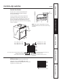
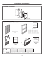
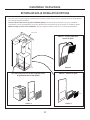
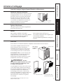
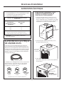
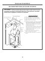
ZONELINE COMPONENTS
Case
Zoneline unit
Front Case Panel
REQUIRED ACCESSORIES
(Check the “Essential Elements” label on the unit.)
Architectural Louver
RAVAL1
Wall Plenum
RAVWP6 - 6″D x 19
3
⁄4″W x 32″H
RAVWP8 - 8″D x 19
3
⁄4″W x 32″H
RAVWP12 - 12″D x 19
3
⁄4″W x 32″H
RAVWP15 - 15″D x 19
3
⁄4″W x 32″H
Cutout
Dimensions:
20″ W x 32
1
⁄4″ H
Access Panel with
Return Air Grille
RAVRG1
Return Air Grille
RAVRG2
Cutout
Dimensions:
28″W x 48″H
Cutout
Dimensions:
20
3
⁄8″W x 20
3
⁄8″H
OR
Wall Thermostat
Model Type Mechanical Thermostat Electronic Thermostat
Heat/Cool Models 4-wire 5-wire
Heat Pump Models 6-wire 6-wire
Check the thermostat instructions for correct wiring and installation requirements.
30″
50″
22
1
⁄2″
22
1
⁄2″

Installation Instructions
15
TYPICAL UTILITY CLOSET AND DIMENSIONS
(FOR REFERENCE ONLY)
Side View
Top View
Architectural Louver
10″
duct
Door/access panel
3″ min.
5″ min.
Unit front
3″
min.
14″ min. – Required only if optional Hydronic
Heating Kit (RAVHW1, RAVHW2, RAVHW3) is to
be installed. Clearance for installation should be
taken into consideration if this kit is to be used.
Exterior/Outside
Outside wall
Wall
plenum
Inside wall
Air discharge
outlet
Rigid
ductwork
Flexible or
rigid duct
Wall plenum
divider
31″
Option 1
Access panel with
return air grille
Option 2
Return air grille
Filter bracket
Secure platform
to the floor
Platform: 23
1
⁄4″ x23
1
⁄4″ square
Min. load capacity: 175 lbs.
• 4″ min. from front of case – Unit
installed through FRONT of case.
• 5″ min. from front of case – Unit
installed through SIDE of case.
• 3″ min. from two sides of case.
Plenum
cutout
32
1
⁄4″ H
x 20″ W
Drain fittings
3
⁄4″
Outside wall
Platform
Wall plenum
Field supplied
outer flashing
10″
11
1
⁄2″
A
B
A Minimum recommended access door width: 30″
B Minimum recommended access door height: 50″
UNIT INSTALLED THROUGH SIDE OF CASE
Top View
Architectural Louver
10″
duct
Door/access panel
3″ min.
4″ min.
Unit
front
3″
min.
10″
11
1
⁄2″
UNIT INSTALLED THROUGH FRONT OF CASE
Bottom of case approx. 2″
above bottom of plenum
8″ min.
for drain
access
Bottom of case approx. 2″
above bottom of plenum
Unit

Installation Instructions
16
UTILITY CLOSET CONNECTION LOCATIONS
IMPORTANT: Plan and locate plenum, wall plug, drains and
thermostat carefully to avoid interference. Hard-to-reach locations
will make installation and service difficult!
Reference Dimensions
A Thermostat cable: 9
1
⁄2′ long
B Power cord: 60″ long
C Case width and depth: 23
1
⁄8″
D Case height: 31″
E Condensate drains: 3/4″ connector
• Primary Drain – Centerline of cutout is
approximately 5
1
⁄4″ from left case wall
and 8
1
⁄2″ from back case wall.
• Secondary Drain – Centerline of cutout is
approximately 6
1
⁄2″ from left case wall
and 5
1
⁄4″ from back case wall.
F Typical wall plug: 6″–12″ above case
G Room air sensor kit: 10′ long
Outside wall
Flex duct may be used
for transitions only
Use rigid duct for 90°
bends and tees
F
C
C
D
E
Platform
B
A
230/208 VAC
wall receptacle
or
conduit for direct
connection
G

Installation Instructions
17
RETURN AIR GRILLE INSTALLATION OPTIONS
The room return air grille may be installed toward the front or either side of the unit. Improper return air arrangements
will cause performance problems.
There are three indoor return air grille installation options. Choose the option that best suits your installation
requirements. Follow the Installation Instructions provided with the return air grille accessory for installation details.
NOTE: Use only one filter in the installation. The filter may be installed on the unit or in the access panel/door.
Unit-mounted filter with a field-supplied return
air grille and access door/panel
RAVRG2 – Return air grille
RAVRG1 – Access panel with
return air grille
Filter
Filter
Filter
Outside wall
Option 1
Option 2
Option 3

BUILD AND INSTALL THE ZONELINE
BASE PLATFORM
1. Construct a 23
1
⁄4″ min. x 23
1
⁄4″ min. square platform
with legs to raise the platform a minimum of 8″.
NOTE: The platform must have a load-bearing
capacity of 175 lbs. minimum.
1
Installation Instructions
18
WALL PLENUM AND ARCHITECTURAL LOUVER INSTALLATION
• Install the appropriate wall plenum through the exterior wall in accordance with the Installation Instructions
provided with the plenum.
IMPORTANT: The wall plenum is not designed to carry structural loads.
Proper wall header construction is required. The plenum requires proper flashing,
shim and caulk for a weather resistant installation.
Properly square
and level plenum.
Proper header for structural
support.
Apply proper caulking
and flashing.
Architectural Louver—
RAVAL1
Exterior/Outside Wall
Case
Wall Plenum
RAVWP6 – 6″D x 19
3
⁄4″W x 32″H
RAVWP8 – 8″D x 19
3
⁄4″W x 32″H
RAVWP12 – 12″D x 19
3
⁄4″W x 32″H
RAVWP15 – 15″D x 19
3
⁄4″W x 32″H
2. Make drain hole cutout(s):
• Primary Drain – Centerline of drain is
approximately 5
1
⁄4″ from left platform edge
and 8
1
⁄2″ from back platform edge.
• Secondary Drain – Centerline of drain
is approximately 6
1
⁄2″ from left platform edge
and 5
1
⁄4″ from back platform edge.
3. Place the platform in the utility closet
with the following clearance between it
and the interior surface of the walls/door/panel:
• 4″ min. from front of the case –
Unit to be installed through FRONT of case
• 5″ min. from front of the case –
Unit to be installed through SIDE of case
• 3″ min. from two sides of the case
4. Align the platform with the opening of
the wall plenum and secure to the floor
using appropriate brackets and bolts.
23
1
⁄4″ min.
8″ min.
for drain
access
Cutout for drain
connection(s)
(see NOTE below)
Back of platform
Left side of platform
NOTE: Specific cutout size
for drain connections needs
to be determined by the installer
for the given installation situation.
5
1
⁄4″
23
1
⁄4″ min.
5
1
⁄4″
6
1
⁄2″
8
1
⁄2″

INSTALL THE DRAIN(S)
An external or an internal drain must be attached
to the primary drain connector. A secondary drain
is supplied if required by state and local codes. Refer
to the local codes for proper installation of the drains.
If the secondary drain is not used, seal its drain port
with a 3/4″ MNPT plug.
External Drain
Attach a 90° PVC elbow to the unit’s female 3/4″ NPT
drain connector. Use the other end of the elbow to run
a 3/4″ Sch. 40 PVC pipe through the knockout holes of
both the wall plenum and the architectural louver to the
outside. Seal the gap between the plenum hole and PVC
tube. See the Installation Instructions in the RAVAL1.
Internal Drain
Attach PVC to the unit’s female 3/4″ NPT drain
connector. See the Installation Instructions
in the RAVAL1. Local codes may apply.
2
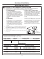
DUCTWORK
Prepare the closet ductwork for later connection
to the case.
The total flow rate (CFM) and external static pressure
(ESP) available can be estimated from the chart below.
Use these charts to select your fan speed setting. The
collar on top of the case accepts standard 10″ duct.
Pull all duct tight. Extra duct slack can greatly increase
static pressure.
CAUTION: Flex duct can collapse and
cause airflow restrictions. Do not use flex duct for 90°
bends or unsupported runs of 5 ft. or more.
3
Installation Instructions
Your airflow should be balanced based on many factors,
such as available ESP, room CFM, and ductwork. Consult
an HVAC engineer for proper applications. External static
pressure (ESP) can be measured with a manometer or
pitot tube. Once this ESP is established, you can
calculate the CFM using the above chart.
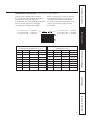
CFM Recommendations
9,000 BTU 12,000 BTU 18,000 BTU
275 300 325 350 375 400 450 500 550
•••
• = Recommended Mid Range
Higher CFMs tend to increase Sensible capacity,
enhance room circulation and increase duct noise,
while lower CFMs tend to increase Latent capacity
and reduce noise.
Side View
Inside wall
Female drain
fitting
3
⁄4″
PVC
90° Elbow
PVC
(External drain)
PVC
(Internal drain)
Side View
Inside wall
Female drain
fitting
3
⁄4″
Airflow – CFM@230 Volts and @ 265 Volts
Indoor Fan CFM
DUCT SELECT SWITCH
UP DOWN
ESP
(in. water)
High
CFM
Medium
CFM
Medium
CFM
Low
CFM
0.0
0.1
0.2
0.3
0.4
390
370
350
330
310
340
320
300
280
260
340
320
300
280
260
305
290
270
250
230
0.0
0.1
0.2
0.3
0.4
475
450
425
400
375
390
370
350
330
315
390
370
350
330
315
350
325
300
275
250
0.0
0.1
0.2
0.3
0.4
630
610
590
570
550
545
530
515
495
475
545
530
515
495
475
490
480
470
455
440
AZ75(H/E)09AZ75(H/E)12AZ75(H/E)18
To correct for 208 volts: 0.91
19

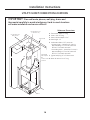
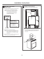
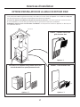
INSTALL AND CONNECT THE CASE
1. Remove the front case panel and pull
the unit out of the case. Place the empty case onto
the platform in the closet with the outdoor side facing
the wall plenum opening. Align the case with plenum
opening and attach with six field-supplied sheet metal
screws (corrosion-resistant screws recommended).
2. Adjust all four leveling legs until the case is level.
3. Using field-supplied screws, bolt the case
to the platform.
4. Connect the internal or external drain(s) as necessary.
4
Installation Instructions
INSTALL AND GROUND
THE UNIT TO THE CASE
UNIT INSTALLED THROUGH FRONT OF CASE
1. Slide the back of the unit into the case. Push the unit
all of the way into the case until it stops.
NOTE: Either of the case sides may be removed
to enable the unit to be slid into the case.
2. Ground the unit to the case by installing the front
case-to-unit hex-bolt and/or case-to-unit side screw.
5a
Hex bolt
Air
discharge
outlet
Rigid
ductwork
Inside
wall
20
Primary female
drain fitting
3
⁄4″
Leveling legs
INSTALL AND GROUND
THE UNIT TO THE CASE
UNIT INSTALLED THROUGH SIDE OF CASE
1. Slide the side of the unit into the case. Push the unit
all of the way into the case until it stops.
NOTE: Either of the case sides may be removed
to enable the unit to be slid into the case.
2. Attach the case side panel to the main case.
3. Ground the unit to the case by installing the front
unit-to-case hex-bolt and/or case-to-unit side screw.
5b
Side screw
Hex bolt
Side screw
(may be
installed on
either side)
External
drain
OR
Internal
drain(s)
Bolt case to
platform
Secondary
3
⁄4″ drain
option. If not used,
seal with a MNPT plug
NOTE: Piping is not
supplied with the unit.
Obtain locally.
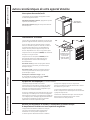
La page est en cours de chargement...
La page est en cours de chargement...
La page est en cours de chargement...
La page est en cours de chargement...
La page est en cours de chargement...
La page est en cours de chargement...
La page est en cours de chargement...
La page est en cours de chargement...
La page est en cours de chargement...
La page est en cours de chargement...
La page est en cours de chargement...
La page est en cours de chargement...
La page est en cours de chargement...
La page est en cours de chargement...
La page est en cours de chargement...
La page est en cours de chargement...
La page est en cours de chargement...
La page est en cours de chargement...
La page est en cours de chargement...
La page est en cours de chargement...
La page est en cours de chargement...
La page est en cours de chargement...
La page est en cours de chargement...
La page est en cours de chargement...
La page est en cours de chargement...
La page est en cours de chargement...
La page est en cours de chargement...
La page est en cours de chargement...
La page est en cours de chargement...
La page est en cours de chargement...
La page est en cours de chargement...
La page est en cours de chargement...
La page est en cours de chargement...
La page est en cours de chargement...
La page est en cours de chargement...
La page est en cours de chargement...
-
 1
1
-
 2
2
-
 3
3
-
 4
4
-
 5
5
-
 6
6
-
 7
7
-
 8
8
-
 9
9
-
 10
10
-
 11
11
-
 12
12
-
 13
13
-
 14
14
-
 15
15
-
 16
16
-
 17
17
-
 18
18
-
 19
19
-
 20
20
-
 21
21
-
 22
22
-
 23
23
-
 24
24
-
 25
25
-
 26
26
-
 27
27
-
 28
28
-
 29
29
-
 30
30
-
 31
31
-
 32
32
-
 33
33
-
 34
34
-
 35
35
-
 36
36
-
 37
37
-
 38
38
-
 39
39
-
 40
40
-
 41
41
-
 42
42
-
 43
43
-
 44
44
-
 45
45
-
 46
46
-
 47
47
-
 48
48
-
 49
49
-
 50
50
-
 51
51
-
 52
52
-
 53
53
-
 54
54
-
 55
55
-
 56
56


GE AZ75H09DAC Owner's Manual and Installation Instructions
- Catégorie
- Climatiseurs split-system
- Taper
- Owner's Manual and Installation Instructions
- Ce manuel convient également à
dans d''autres langues
- English: GE AZ75H09DAC
Documents connexes
-
GE 3800 Manuel utilisateur
-
-
-
-
-
-
-
GE AZ65H12DAC Mode d'emploi
-
-
