Team Losi TEN-SCTE Instructions Manual
- Catégorie
- Jouets télécommandés
- Taper
- Instructions Manual


2 - EN
2 -
E
2 -
E
EN
N
EN
N
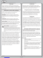
Notice
Notice
All instructions, warranties and other collateral documents are
subject to change at the sole discretion of Horizon Hobby, Inc.
For up-to-date product literature, visit www.horizonhobby.com
and click on the support tab for this product.
Meaning of Special Language
The following terms are used throughout the product
literature to indicate various levels of potential harm when
operating this product:
NOTICE: Procedures, which if not properly followed, create
a possibility of physical property damage AND a little or no
possibility of injury.
CAUTION: Procedures, which if not properly followed, create
the probability of physical property damage AND a possibility
of serious injury.
WARNING: Procedures, which if not properly followed, create
the probability of property damage, collateral damage, and
serious injury OR create a high probability of super cial injury.
WARNING: Read the ENTIRE instruction manual to
become familiar with the features of the product before
operating. Failure to operate the product correctly can
result in damage to the product, personal property and
cause serious injury.
This is a sophisticated hobby product and NOT a toy. It must be
operated with caution and common sense and requires some
basic mechanical ability. Failure to operate this Product in a safe
and responsible manner could result in injury or damage to the
product or other property. This product is not intended for use
by children without direct adult supervision. Do not attempt
disassembly, use with incompatible components or augment
product in any way without the approval of Horizon Hobby,
Inc. This manual contains instructions for safety, operation
and maintenance. It is essential to read and follow all the
instructions and warnings in the manual, prior to assembly,
setup or use, in order to operate correctly and avoid damage or
serious injury.
Introduction
Introduction
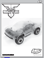
Thank you for choosing the TEN-SCTE. We are con dent you will
be satis ed with the performance of this durable and resilient
vehicle. Please read through the entire manual before setting
up and using your vehicle.
Register your Losi
Register your Losi
®
®
Product Online
Product Online
Register your TEN-SCTE now and be the rst to nd out about
the latest options parts, product updates and more. Log on to
www.LOSI.com and follow the product registration link to stay
connected.
Getting Ready
Getting Ready
Thoroughly read all the enclosed material, precautions and
follow instructions to avoid damaging your new RC vehicle. If
you choose to not follow these steps or instructions, it will be
considered negligence. If after review of this manual and prior
to running your TEN-SCTE, you determine this RC vehicle is not
what you want—Do Not proceed and Do Not run the TEN-SCTE.
If the TEN-SCTE has been run, your local hobby store will not be
able to process a return or accept it for exchange.
Safety Precautions and Guidelines
Safety Precautions and Guidelines
Age Recommendation: Not for children under 14 years. This
is not a toy.
Always operate this RC model in a safe, reasonable and cautious
fashion. When driving the TEN-SCTE avoid someone being hit
by the vehicle. You may cause serious injury to another person,
or to personal property should you make contact while running
the TEN-SCTE.
General
• This RC Vehicle is not intended for use on public highways
or roads.
• Avoid areas that have many pedestrians or crowds of
people.
• Keep in mind that this vehicle is radio controlled and can
experience moments of radio loss or interference, provide
for a margin of error at all times.
• Be aware that the motor and batteries of this RC vehicle
will get HOT during each use. Be careful not to burn
yourself.

3 - EN
3 -
E
3 -
E
EN
N
EN
N
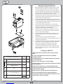
Peak Detection Charger
Peak Detection Charger
Peak detection chargers monitor the battery during charging
and automatically shut o upon full charge. You can either
purchase a peak detection charger that plugs into a household
AC wall socket or one that requires you to also purchase a 12V
power supply.
If using a charger other than a peak detection charger, make
sure your battery is fully discharged prior to charging. Many of
these have a 15–20 minute timer that allows you to set a charge
time. If the battery is not fully discharged, you can potentially
over-charge your battery pack. Do not charge any battery
unattended, and monitor for heat build up. If the battery pack
is more than warm to the touch, immediately discontinue
charging. Read all safety precautions supplied by the charger
and battery manufacturer.
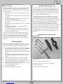
Supplied and Required Equipment
Supplied and Required Equipment
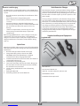
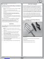
Supplied tools:
Wheel Wrench
Four (4) Hex “L” Wrench Set
.050-inch, 1/16-inch, 5/64-inch, and 3/32-inch
Shock Bottom wrench
Turnbuckle/Shock Top wrench
Batteries and Charging
The TEN-SCTE uses rechargeable batteries such as NiMH. These
batteries all have special requirements to preserve performance
and last.
• Read all instructions provided by the manufacturer of the
batteries.
• Never allow minors to charge battery packs.
• Always check to ensure the polarity of battery connection
is correct.
• Never leave batteries unattended while charging.
• Never charge a battery while it is installed in the TEN-SCTE.
• Do not charge any battery that appears to have any
damage.
• I f there are exposed wires, do not charge or use the
battery until you install shrink-wrap or replace the
complete wire.
When charging NiMH batteries, select a charger to meet your
requirements. You need a charger that is a 100-240V wall
charger or one which requires a 12V power supply. Follow the
charger manufacturer’s instructions and precautions during
each use.
Quick Start
Quick Start
Note: Please read the entire manual to gain a full understanding
of the TEN-SCTE vehicle, ne-tuning the setup and performing
maintenance.
1. Read the safety precautions found on this page.
2. Charge the battery pack you have chosen (NOT
INCLUDED). Refer to the Manufacturer’s Supplied
instructions for battery charging information.
3. Install the AA batteries into the Transmitter. Use alkaline or
rechargeable batteries only.
4. Install a fully charged battery pack.
5. Turn on the transmitter and then the vehicle. Always turn
the transmitter on before the vehicle and turn it o after
the vehicle has been turned o .
6. Check steering. Verify that the servo is functioning
properly.
7. Driving the TEN-SCTE.
8. Performing maintenance of the TEN-SCTE.

4 - EN
4
4
4-
4-
4
EN
EN
EN
EN
EN
4
4
4-
4-
4
EN
EN
EN
EN
EN
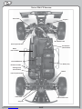
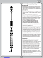
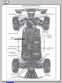
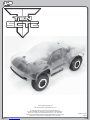
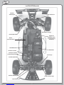
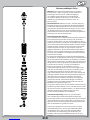
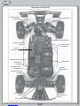
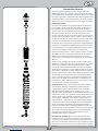
The Losi TEN-SCTE Overview
The Losi TEN-SCTE Overview
Rear Shock
Motor
(not included)
Sway Bar
Sway Bar
Front Suspension Arm
Steering Servo
(not included)
Center Di erential
Receiver Location
Rear Suspension Arm
Rear Camber Link
Battery Tray
Tie Rod
ESC with Fan
(not included)
Front Camber Link
Front Shock

5 - EN
5 -
E
5 -
E
EN
N
EN
N
Tools You Will Find Handy
In addition to the tools included with the TEN-SCTE, you will
nd the following both useful and in some cases necessary.
• Small at blade and Phillips screwdrivers
• Needle-nose pliers
• Quality .050-inch, 1/16-inch, 5/64-inch, 3/32-inch, 1.5mm
and 2.5mm hex (Allen) drivers
Required Equipment:
Electronic Speed Control - We recommend the Xcelorin®
Sensored Brushless Speed Control
Motor - Any 550-sized motor
Battery - We recommend the Xcelorin 7.4V 60C 2S 6000mAh
LiPo (LOSB9877)
Charger - We recommend the Xcelorin MultiPro™ Intelligent
LiPo Balancing Charger (LOSB9606)
Servo - Preferably Spektrum™ S6040
Pinion Gear - Any Mod 1 Pinion Gear
Note: We recommend a Losi LOSA3576 16T pinion gear for 4.5T
550 can motor, or a Losi LOSA3577 17T pinion gear for 5.5T 550
can motor.
Two Channel Radio - We recommend a Spektrum DX3R or DX3S
transmitter and matching receiver.
Paint (always test the paint on material removed from the body
to make sure the paint and body material are compatible.)
Basic Electronics Installation Instructions
Basic Electronics Installation Instructions
Caution: Please be sure to follow the electronics
manufacturers guidelines when installing and setting up
your radio, motor, servo, electronic speed control, and
battery.
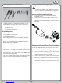
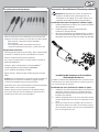
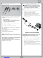
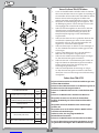
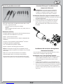
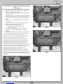
Motor Installation: Follow diagram below
1. Install motor adapter onto motor with two supplied
M3x10mm screws.
2. Install pinion gear (recommendations supplied earlier).
3. Slide motor with adapter into motor mount, set mesh, and
tighten using 5-40 x 3/8 button head screw. Be sure to use
threadlock.
Receiver and Electronic Speed Control Installation:
Receiver and Electronic Speed Control Installation:
Install with double-sided tape. Be sure to route wires so they
will not get caught in the spur gear.
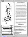
Servo Installation: (use following diagrams)
1. Install servo as shown in diagram using the four supplied
4-40 x 1/2 in screws and washers. Please look at supplied
chart to determine if spacers are needed.
2. Choose correct servo horn adapter using servo horn chart
and press onto servo.
3. After servo is centered, install servo horn on servo using
the screw provided with your servo so that in the centered
position the servo horn is parallel to the servo saver arm.

6 - EN
6 -
E
6 -
E
EN
N
EN
N
Servo Manufacturer, Make/ModelServo
Spacer
Servo
Horn
JR
All (DZ9100T/S Needs Spacer) No 23T
Airtronics
Sanwa
94357Z, 94358Z, 94649Z, 94360Z,
94452Z, 94758Z, 94737Z, 94738ZYes
23T
94102Z, 94112ZYes
Hitec
All No 24T
Futaba
All (S9102 DOES NOT FIT)No25T
KO
PROPO
PDS-2123, 2344, 2363, 2365, 2366 No 23T
No
Before Running Your TEN-SCTE
Before Running Your TEN-SCTE
1. Break in the di erentials. While holding the chassis with
only the left side tires rmly on the ground, give the car
about one eighth throttle, for 30 seconds. The right side
tires should spin freely during this time. Repeat this with
only the right side tires rmly on the ground, allowing the
left side tires to spin freely. Repeat this 2–3 times.
2. Check for free suspension movement. All suspension arms
and steering components should move freely. Any binds
will cause the car to handle poorly.
3. Set the ride height. Set the ride height of your truck with
all components installed so that the bottom of the chassis
is 29.5mm from the ground in the front and 24.5mm in the
rear by adjusting the shock collars.
4. Set the camber. Adjusting the camber tie rod length
changes the camber. Set the front tires to have 0 degrees
of camber at ride height. Set the rear tires to have 2.5
degrees of negative camber at ride height.
5. Set the front toe-in. Adjust the steering tie rods so that
when the servo is centered on the transmitter, the front
tires are both pointing straight.
6. Charge a battery pack. Charge a battery pack as per the
battery manufacturers and/or charger manufacturers’
instructions.
7. Adjust the electronic speed control. Follow the
manufacturers instructions to setup and adjust the speed
control for your TEN-SCTE.
8. Set the transmitter steering trim. Follow the manufacturers
instructions to set the steering trim/subtrim so that the
vehicle goes straight with no input to the steering.
9. Set the transmitter steering endpoints. Follow the
manufacturers’ instructions to set the endpoints so that
the servo hits full steering upon reaching full input from
the transmitter.
Driving the TEN-SCTE
Driving the TEN-SCTE
Always follow these precautions when running your TEN-
SCTE.
Do not run the TEN-SCTE at dusk or in the dark when
visibility is limited.
Do not attempt to run this model if it will be out of sight for
any amount of time.
Do not run this model near a crowd of people.
Always check for proper radio function and battery condition
before operating.
Check to make sure the tires are securely glued to the rims.
Check the model thoroughly for loose nuts, bolts and screws
before and after running.
Make sure you use proper dirt tires if running o -road.
Never run the model with old or discharged batteries.
Leave plenty of room to stop the model. It will take as much
room to stop as it did to accelerate.

7 - EN
7 -
E
7 -
E
EN
N
EN
N
Tuning, Adjusting and Maintaining the TEN-SCTE
Tuning, Adjusting and Maintaining the TEN-SCTE
Periodically examine your TEN-SCTE for the following:
• Keep your vehicle clean using a brush to remove dirt
and dust.
• Look for cracks in the suspension arms and other
molded parts.
• Check that the tires are still glued to the wheels.
• Check that all the wheel bearings are clean and lubricated.
• Using your tools, attempt to tighten all the screws and
nuts.
• Verify that the Camber Links and Steering linkage are
not bent.
• Check that the Toe and Camber settings are as desired
and equal.
• Check the Drivetrain:
o Check the Spur gear for wear.
o Check the Pinion gear.
• Take the shocks o the vehicle and check, especially if they
appear to be leaking as it is time to rebuild them.
• Look over all the wiring and connections for bare wire or
any place which could lead to a short circuit.
After you become familiar with driving your TEN-SCTE,
you may need to reset or make adjustments for better
driving performance.
Just as in a real car, alignment is an important factor in your
vehicle’s handling. When you are ready to make adjustments
it is a good idea to have a at work space to place your vehicle
on. This will enable you to easily and more quickly make both
Toe-in and Camber adjustments. These adjustments should be
set with the vehicle sitting at its normal ride height.
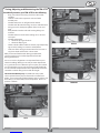
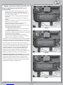
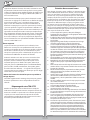
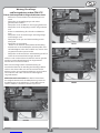
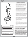
Three-Position Battery Tray: Your TEN-SCTE comes with
a three-position battery tray to alleviate the need for foam
blocks. You can move the included battery stops in order to run
the battery in a back, middle, or forward position. Please see
pictures as follows.
BACK
MIDDLE
FORWARD

8 - EN
8 -
E
8 -
E
EN
N
EN
N
Tuning the Front End of the TEN-SCTE
Shock Location: The TEN-SCTE has three mounting locations
on the front shock tower. The position can be easily adjusted
by simply moving the top of the shock to another hole. The
standard location works best on most surfaces. Moving the
top of the shock inward a hole will slow steering response
and make the TEN-SCTE smoother in bumps. The standard
position on the arm is middle, which o ers the best balance.
Running the inside shock location will give the TEN-SCTE more
steering into the turn and less steering on corner exit. Running
the shock location outside on the front arm will give you less
overall steering into the turn and keep the front end atter
through the turn, making the TEN-SCTE smoother and easier to
drive. This can be used on high-traction surfaces. Keep in mind
as you move the shocks in on the arm this will require internal
limiters to obtain the correct suspension travel. For the inside
location a total of .200-inch limiter works great. Losi sells a
shock spacer set (LOSA5050) that includes .030-inch, .060-inch,
.090-inch and .120-inch spacers.
All of the Camber and Steering linkages feature left and
right-hand threads at either end like a turnbuckle to make
adjustments easy. The side with right-hand threads has a small
groove machined into it. Use the plastic turnbuckle wrench
supplied with the TEN-SCTE to adjust these. Using the right-
hand threaded side as your reference: if you turn the link to the
right (clockwise) you will make it shorter. If you turn it to the left
(counterclockwise) you will make it longer. If you will be making
a lot of adjustments-you should consider using the LOSA99165
Aluminum Turnbuckle Wrench.
Static Camber: This refers to the angle of the wheels/tires
relative to the surface (viewed from either the front or back).
Negative camber means that the top of the tire leans in toward
the chassis. Positive camber means the top of the tire leans out,
away from the chassis. Camber can be precisely measured with
after-market camber gauges, sold at a local hobby shop. It can
be measured (roughly) using any square (to the ground) object
by checking the gap between the square edge and the top of
the tire. Testing has shown that 1 degree of negative camber
is best for most track conditions. Increasing negative camber
(in the range of 1-2 degrees) will generally increase steering.
Decreasing negative camber (in the range of 0-1 degree) will
generally decrease steering and the TEN-SCTE will feel easier to
drive as a result. This is, most often, a very critical adjustment in
tuning your TEN-SCTE that can be made quickly and easily.
Maintenance
Maintenance
In addition to the service needs pointed out in this guide,
you should try to maintain your new TEN-SCTE for proper
performance and to prevent wear. If dirt gets in the moving
parts it can seriously hinder the performance of the model.
Use compressed air, a soft paintbrush and/or a toothbrush
to remove dirt and dust. Avoid using solvents, if possible, as
this can actually wash the dirt into bearings and areas not
accessible without disassembly, causing additional wear. We
suggest you follow these basic guidelines.
• Remove as much freestanding dirt and dust as noted
above.
• Never leave the battery plugged in while vehicle is not
running.
• Inspect the chassis for worn, broken or binding parts and
repair as necessary.
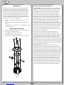
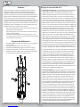
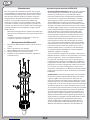
Maintaining Di erentials:
Maintaining Di erentials:
1. Remove di erential from vehicle using exploded view.
2. Clean loose dirt o using brush.
3. Open di erential as shown in diagram.
4. Clean out internals using motor spray.
5. Fill with oil to your liking and reverse steps to reinstall.

9 - EN
9 -
E
9 -
E
EN
N
EN
N
Tuning the Rear End of the TEN-SCTE
Shock Location: Moving the shocks out on the arm will result
in less forward traction and let the TEN-SCTE make more of
an arc through the exit of the turn. In general, when changing
shock locations on the arm, it will be necessary to go down one
spring rate when moving out on the arm.
Static Camber: Having the same de nition as for the front end
and measured in the same fashion, rear camber can also be a
critical tuning feature. Testing has shown that running a small
amount of negative camber (.5-1 degree) is best. Increasing
negative rear camber (in the range of 1.5-3 degrees) will
increase stability and traction in corners, but decrease high-
speed stability. Decreasing rear camber (in the range of 0-1.5
degrees) will decrease stability and traction in corners, but will
increase high-speed stability.
Inboard Camber Location: The TEN-SCTE has two inner
camber link locations. These locations work in the same
fashion and have the same e ect as noted for the front. You
will nd that you will get more noticeable changes with the
outer locations in the hub. In general the upper hole will make
the TEN-SCTE more stable and keep the front end atter. This
works well on higher traction surfaces. The lower location will
make the steering more aggressive which works well on lower
traction surfaces. This can be good in some conditions but can
also make the TEN-SCTE di cult to drive in others.
Outboard Camber Location: Running the camber link in the
inside position on the hub will generate more rotation entering
a turn, but decrease steering on exit. Running the camber link
in the furthest outer position on the hub will generate more
stability entering a turn and increase steering on exit.
Toe-In: Having the same de nition as for the front end, the
toe-in can be adjusted on the TEN-SCTE with the rear hubs. The
stock toe-in is 3 degrees of inboard per side and 0 degrees in
the hub. Increasing rear toe-in will increase forward traction
and initial steering, but reduce straightaway speed. Decreasing
rear toe-in will decrease forward traction and “free-up” the TEN-
SCTE. Less toe-in can be used to gain top speed.
Ride Height: This is the height of the chassis in relation to the
surface. It is an adjustment that a ects the way your TEN-
SCTE jumps, turns and goes through bumps. To check the
ride height, drop one end (front or rear) of the TEN-SCTE from
about a 5 to 6-inch height onto a at surface. Once the TEN-
SCTE settles into a position, check the height of that end of the
TEN-SCTE in relationship to the surface. To raise the ride height,
lower the shock adjuster nuts on the shock evenly on the end
(front or rear) of the TEN-SCTE that you are working on. To lower
the ride height, raise the shock adjuster nuts. Both left and right
nuts should be adjusted evenly. Check the setup sheet included
and for additional setup information visit www.losi.com.
Inboard Camber Location: The TEN-SCTE has two di erent
inner locations with vertical adjustment for the front camber
tie rod. In general, the lower or further out the inside position
is, relative to the outside, the more camber gain (total camber
change through the total throw of the suspension) is present.
This is an adjustment that is di cult to make a generic
statement as it can have slightly di erent results in various
conditions. The following is a summary of how this adjustment
will usually impact the handling of the TEN-SCTE. A longer front
camber link will usually make the TEN-SCTE feel sti er. This will
help keep the TEN-SCTE atter with less roll, but can make the
TEN-SCTE handle worse in bumpy conditions. It also will make
the TEN-SCTE easier to drive. A shorter front camber link will
result in more front end roll, which will provide more steering
on tighter turns with the loss of some stability. You will also lose
some high-speed steering but might gain some more steering
response. Too short of a front link may make the TEN-SCTE feel
“twitchy” or “wandery” meaning that it may be di cult to drive
straight at high speed.
Toe-In/Out: This is the parallel relationship of the front tires to
one another. Toe-in/out adjustments are made by changing the
overall length of the steering tie rods. Toe-in (the front of the
tires point inward, to a point in front of the front axle) will make
the TEN-SCTE react a little slower, but have more steering from
the middle of the turn, out. The opposite is true with toe-out
(the front of the tires point outward, coming to a point behind
the front axle), the TEN-SCTE will turn into the corner better but
with a decrease in steering from the middle of the turn, out.
Toe-in will help the TEN-SCTE to “track” better on long straight
high-speed runs, where toe-out has a tendency to make the
TEN-SCTE wander. We recommend to run between 0-degree of
toe-in/out to 1 degree of toe-in.
Di erentials: The TEN-SCTE comes equipped with grease
in all three di erentials. You can switch to oil. Thinner front
oil increases o -power steering, but if the oil is too thin the
steering will become grabby and inconsistent. Thicker front
di erential oil increases o -power stability and increases on-
power steering. Thinner center di erential has less forward
drive, can unload more under acceleration and is easier to drive
on rough and slick tracks. Thicker center di erential has more
acceleration, increases on-power steering, and less o -power
steering. Thinner rear di erential has more cornering traction
and increases steering in the middle of the turn. Thicker rear
di erential has less steering in the middle of the turn and more
forward traction.

10 - EN
10
-
10
-
E
N
N
E
E
N
N
Use the same technique to adjust the rear ride height. Again,
refer to the included setup sheet. Every driver likes a little
di erent feel so you should try small ride height adjustment
to obtain the feel you like. This should be the last adjustments
you make after everything else is dialed in. Note: Do not use
ride height adjustments as a substitute for a spring rate change.
If your TEN-SCTE needs a softer or rmer spring, change the
spring. Do not think that simply moving the shock nuts will
change the spring sti ness as it will NOT!
Wheels and Tires
The tires come pre-mounted with the vehicle and should be
checked to make certain they stay glued to the wheels. The
wheel spinning speeds this vehicle is capable of tend to pull the
rubber tire away from the rim. When a tire or tires come loose
from the rim you will notice the vehicle is hard to control.
Tip the vehicle on its side and using both hands to hold one
wheel at a time, use your thumb to press the tire away from the
rim. If you see a tire pull away from the rim, use Losi Tire Glue
(LOSA7880 thick or LOSA7881 thin) to reglue. It only takes a
small drop of glue generally. Be careful—this is CA-type glue
and you do not want to glue your ngers to the wheel and tire.
Use safety goggles when gluing tires.
Check the mounting of the tire periodically to ensure proper
performance and handling.
Troubleshooting your TEN-SCTE
Troubleshooting your TEN-SCTE
Many questions are the result of simple user errors or minor
adjustments which are easily addressed. If after reading below
you cannot resolve your problem, then please contact the
appropriate Horizon product support department.
Servicing Your Shocks
Servicing Your Shocks
From time to time you should check your shocks for adequate
uid. If the uid is low, or it is getting dirty, you should change
the uid in the shocks. You may also want to change the shock
uid and or the pistons to better address the conditions you
are running on. Regardless of what the reason you will want to
follow these simple steps to service, re ll, and bleed your TEN-
SCTE shocks. If you are cleaning or changing the uid, you will
nd the LOSA99217 Nitrotec™ Spray Cleaner to be the quickest
and easiest way to remove oil uid and dirt safely.
1. If you are changing the pistons, clean the threads on the
end of the shock shaft and apply threadlock (LOSA99202)
to the threads.
2. Install the small shock piston washer and shock piston
using the 4-40 mini lock nut on the shock shaft to secure
them.
3. Put a drop of shock uid on the shaft before replacing it in
the shock body.
4. If you are changing the shock end, use the shock tool
provided with the TEN-SCTE to hold the shaft. You will
see that this plastic tool has serrations on both sides that
allow you to hold it with a pair of pliers and not scratch up
the micro nished surface. This method works very well to
protect the shock shafts from damage.
5. After installing, make sure the shaft is fully extended when
lling the shock.
6. Fill the shock body with 30–35-weight shock uid until it is
to the top of the Body.
7. Work the shock shaft up and down a few times. This will
release the air bubbles trapped beneath the piston.
8. Place the lled shock, in the upright position, o to the
side for a few minutes until the air bubbles escape from
the uid.
9. Once all the air bubbles are out of the uid, gently place
the shock bladder onto the top of the shock. Some uid
will “bleed” from around the bladder.
10. Screw the shock cap onto the body until a little resistance
is felt.
11. Slowly push the shock shaft up. This will allow excess uid
to bleed out.
12. Tighten the cap all the way down using the shock tools
included in your kit.
13. Move the shock shaft up and down. The shaft should be
easy to push up into the body of the shock.
14. If increased pressure is felt towards the top, there is too
much oil in the shock. Loosen the shock cap and bleed the
shock as done in steps 11 and 12.
15. Make sure each pair (front/rear) of shocks has the same
rebound and compression. This is checked by holding
one shock in each hand horizontally and pushing them
together by the shock end. Watch carefully to ensure that
both compress evenly. Now release both shocks and again
watch carefully as they should rebound the same.

11 - EN
11
- E
11
- E
E
N
N
E
N
N
Warranty and Repair Policy
Warranty and Repair Policy
Warranty Period
Exclusive Warranty- Horizon Hobby, Inc., (Horizon) warranties
that the Products purchased (the “Product”) will be free from
defects in materials and workmanship at the date of purchase
by the Purchaser.
Limited Warranty
Horizon reserves the right to change or modify this warranty
without notice and disclaims all other warranties, express or
implied.
(a) This warranty is limited to the original Purchaser
(“Purchaser”) and is not transferable. REPAIR OR REPLACEMENT
AS PROVIDED UNDER THIS WARRANTY IS THE EXCLUSIVE
REMEDY OF THE PURCHASER. This warranty covers only those
Products purchased from an authorized Horizon dealer. Third
party transactions are not covered by this warranty. Proof of
purchase is required for all warranty claims.
(b) Limitations- HORIZON MAKES NO WARRANTY OR
REPRESENTATION, EXPRESS OR IMPLIED, ABOUT NON-
INFRINGEMENT, MERCHANTABILITY OR FITNESS FOR A
PARTICULAR PURPOSE OF THE PRODUCT. THE PURCHASER
ACKNOWLEDGES THAT THEY ALONE HAVE DETERMINED THAT
THE PRODUCT WILL SUITABLY MEET THE REQUIREMENTS OF
THE PURCHASER’S INTENDED USE.
(c) Purchaser Remedy- Horizon’s sole obligation hereunder shall
be that Horizon will, at its option, (i) repair or (ii) replace, any
Product determined by Horizon to be defective. In the event of
a defect, these are the Purchaser’s exclusive remedies. Horizon
reserves the right to inspect any and all equipment involved
in a warranty claim. Repair or replacement decisions are at
the sole discretion of Horizon. This warranty does not cover
cosmetic damage or damage due to acts of God, accident,
misuse, abuse, negligence, commercial use, or modi cation
of or to any part of the Product. This warranty does not cover
damage due to improper installation, operation, maintenance,
or attempted repair by anyone other than Horizon. Return
of any Product by Purchaser must be approved in writing by
Horizon before shipment.
Damage Limits
HORIZON SHALL NOT BE LIABLE FOR SPECIAL, INDIRECT
OR CONSEQUENTIAL DAMAGES, LOSS OF PROFITS OR
PRODUCTION OR COMMERCIAL LOSS IN ANY WAY CONNECTED
WITH THE PRODUCT, WHETHER SUCH CLAIM IS BASED IN
CONTRACT, WARRANTY, NEGLIGENCE, OR STRICT LIABILITY.
Further, in no event shall the liability of Horizon exceed the
individual price of the Product on which liability is asserted.
As Horizon has no control over use, setup, nal assembly,
modi cation or misuse, no liability shall be assumed nor
accepted for any resulting damage or injury. By the act of use,
setup or assembly, the user accepts all resulting liability.
If you as the Purchaser or user are not prepared to accept
the liability associated with the use of this Product, you are
advised to return this Product immediately in new and unused
condition to the place of purchase.
Law: These Terms are governed by Illinois law (without regard
to con ict of law principals).

12 - EN
12
-
12
-
E
N
N
E
E
N
N
Warranty Services
Warranty Services
Questions, Assistance, and Repairs
Your local hobby store and/or place of purchase cannot provide
warranty support or repair. Once assembly, setup or use of the
Product has been started, you must contact Horizon directly. This
will enable Horizon to better answer your questions and service
you in the event that you may need any assistance. For questions
or assistance, please direct your email to productsupport@
horizonhobby.com, or call 877.504.0233 toll free to speak to a
Product Support representative. You may also nd information on
our website at www.horizonhobby.com.
Inspection or Repairs
If this Product needs to be inspected or repaired, please use
the Horizon Online Repair Request submission process found
on our website or call Horizon to obtain a Return Merchandise
Authorization (RMA) number. Pack the Product securely using a
shipping carton. Please note that original boxes may be included,
but are not designed to withstand the rigors of shipping without
additional protection. Ship via a carrier that provides tracking and
insurance for lost or damaged parcels, as Horizon is not responsible
for merchandise until it arrives and is accepted at our facility. An
Online Repair Request is available at www.horizonhobby.com
http://www.horizonhobby.com under the Repairs tab. If you do
not have internet access, please contact Horizon Product Support
to obtain a RMA number along with instructions for submitting
your product for repair. When calling Horizon, you will be asked
to provide your complete name, street address, email address and
phone number where you can be reached during business hours.
When sending product into Horizon, please include your RMA
number, a list of the included items, and a brief summary of the
problem. A copy of your original sales receipt must be included
for warranty consideration. Be sure your name, address, and RMA
number are clearly written on the outside of the shipping carton.
Notice: Do not ship batteries to Horizon. If you have
any issue with a battery, please contact the appropriate
Horizon Product Support office.
Warranty Inspection and Repairs
To receive warranty service, you must include your original
sales receipt verifying the proof-of-purchase date. Provided
warranty conditions have been met, your Product will be repaired
or replaced free of charge. Repair or replacement decisions are at
the sole discretion of Horizon.
Non-Warranty Repairs
Should your repair not be covered by warranty the repair will
be completed and payment will be required without notification
or estimate of the expense unless the expense exceeds 50% of
the retail purchase cost. By submitting the item for repair you
are agreeing to payment of the repair without noti cation. Repair
estimates are available upon request. You must include this request
with your repair. Non-warranty repair estimates will be billed a
minimum of ½ hour of labor. In addition you will be billed for
return freight. Horizon accepts money orders and cashiers checks,
as well as Visa, MasterCard, American Express, and Discover cards.
By submitting any item to Horizon for inspection or repair, you are
agreeing to Horizon’s Terms and Conditions found on our website
under the Repairs tab.
United States
(Electronics and engines)
Horizon Service Center
4105 Fieldstone Rd
Champaign, Illinois
61822 USA
877-504-0233
Online Repair Request visit:
www.horizonhobby.com/repairs
(All other products)
Horizon Product Support
4105 Fieldstone Rd
Champaign, Illinois
61822 USA
productsupport@horizonhobby.com
877-504-0233
United Kingdom
Horizon Hobby Limited
Units 1-4 Ployters Rd
Staple Tye
Harlow, Essex
CM18 7NS
United Kingdom
sales@horizonhobby.co.uk
+44 (0) 1279 641 097
Germany
Horizon Technischer Service
Hamburger Str. 10
25335 Elmshorn
Germany
service@horizonhobby.de
+49 4121 46199 66
France
Horizon Hobby SAS
14 Rue Gustave Eiffel
Zone d’Activité du Réveil Matin
91230 Montgeron
infofrance@horizonhobby.com
+33 (0) 1 60 47 44 70
Compliance Information for the European Union
Compliance Information for the European Union
INSTRUCTIONS FOR DISPOSAL OF WEEE BY USERS IN
THE EUROPEAN UNION
This product must not be disposed of with other waste. Instead, it
is the user’s responsibility to dispose of their waste equipment by
handing it over to a designated collection point for the recycling
of waste electrical and electronic equipment. The separate
collection and recycling of your waste equipment at the time of
disposal will help to conserve natural resources and ensure that
it is recycled in a manner that protects human health and the
environment. For more information about where you can drop
o your waste equipment for recycling, please contact your local
city o ce, your household waste disposal service or where you
purchased the product.

13 - EN
13
13
13
13
13
E
E
-E
-E
E
N
N
N
N
N
13
13
13
13
13
E
E
-E
-E
E
N
N
N
N
N
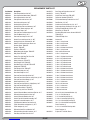
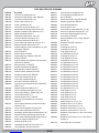
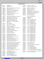
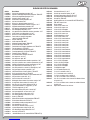
Part Number Description
LOSB2021 Front Suspension Arm Set: 10-T
LOSB2022 Rear Suspension Mount Cover: TEN-SCTE
LOSB2023 Rear Suspension Arm Set: 10-T
LOSB2100 Front Spindles and Carriers: 10-T
LOSB2103 Rear Hubs and Spacers: 10-T
LOSB2123 Steering Bellcrank Set: 10-T
LOSB2124 Steering Posts/Tube and Hardware: 10-T
LOSB2163 Front Shock Towers and Caps: 10-T
LOSB2170 Rear Shock Tower: 10-T
LOSB2211 Front and Rear Pin Mount Cover Set: 10-T
LOSB2213 Pivot Pin Mount Set (4): 10-T
LOSB2222 Front and Rear Sway Bar Set: 10-T
LOSB2278 Chassis Brace and Spacer Set (3): 10-T
LOSB2279 Steering Drag Link and Hardware: 10-T
LOSB2359 Radio Tray with Switch Cover Blank and
Receiver Cover: TEN-SCTE
LOSB2411 Chassis: TEN-SCTE
LOSB2412 Top Brace: TEN-SCTE
LOSB2413 Motor Mount with Adapter: TEN-SCTE
LOSB2414 Body Posts: TEN-SCTE
LOSB2415 Battery Tray with Stop Tab, Foam Pad
and Screws: TEN-SCTE
LOSB2416 Battery Straps (2): TEN-SCTE
LOSB2417 Rear Bumper Pack: TEN-SCTE
LOSB2418 Rear Mud Flap (2): XXX-SCT/TEN-SCTE
LOSB2419 Sideguards: TEN-SCTE
LOSB2421 Front Bumper Pack: TEN-SCTE
LOSB2825 Front Shock Body Set: 10-T
LOSB2826 Rear Shock Body Set: 10-T
LOSB2845 Front and Rear Shock Shaft Set: 10-T
LOSB2904 Front and Rear Shock Plastics and Ball Set (4): 10-T
LOSB2905 Front and Rear Shock Boots (8): 10-T
LOSB2906 Shock Rebuild Set (2): 10-T
LOSB2961 Front and Rear Spring Set (4)–Med (Black): 10-T
LOSB3104 Front and Rear Gearbox Set: 10-T
LOSB3436 40T Spur Gear, Mod 1: TEN-SCTE
LOSB3495 Wheel Hex (4) with Pins: TEN-SCTE
LOSB3536 Center Differential Mount and Shock Tool Set: 10-T
LOSB3542 Differential Housing and Seal Set: 10-T
LOSB3553 Center Differential Outdrive Set: 10-T
LOSB3555 Center Front CV Driveshaft Assembly: 10-T
LOSB3556 Center CV Driveshaft Couplers: 10-T
LOSB3563 F/R Differential Outdrive and Hard Set (2)
LOSB3564 F/R CV Driveshafts and Couplers (2): 10-T
LOSB3565 F/R CV Couplers (4): 10-T
LOSB3568 Differential Seals/Pin and Gasket: 10-T
LOSB3569 Differential Gear Set with Hardware: 10-T
LOSB3571 Front Ring and Pinion Gear Set: 10-T
LOSB3572 Rear Ring and Pinion Gear Set: 10-T
LOSB3574 Axle (2): TEN-SCTE
LOSB3578 Center Rear Drive Shaft: TEN-SCTE
LOSB3592 Differential Standoff: TEN-SCTE
LOSB4003 F/R Camber/Steering Turnbuckle Set: 10-T
LOSB4023 Rod End Set (15): 10-T
LOSB4022 Camber and Steering Ball Set (12): 10-T
LOSB4109 Suspension Hinge and King Pin Set (10): 10-T
LOSB4210 Steering/Throttle/Brake Link Set: 10-T
LOSB7018 Wheel Set (2): TEN-SCTE
LOSB7019 Beadlock Ring with Screws, Chrome:XXX-SCT/
TEN-SCTE (2)
LOSB8028 TEN-SCTE Body, Clear
LOSA4006 Antenna Kit
LOSA6204 4-40 x 1/2 Cap Screws
LOSA6206 4-40 x 3/8 Cap Screws
LOSA6227 4-40 x 1/8 Setscrews
LOSA6229 4-40 x 3/8 Button Head Screws
LOSA6240 5-40 x 1/2 Cap Screws
LOSA6250 4mm and 5mm Setscrews
LOSA6254 2-56 x 1/4 Cap Screws
LOSA6256 4-40 x 1/2 Button Head Screws
LOSA6264 8-32 x 3/8 Flat Head Screws
LOSA6270 5-40 x 3/8 Flat Head Screws
LOSA6271 5-40 x 1/2 Flat Head Screws
LOSA6272 5-40 x 3/4 Flat Head Screws
LOSA6275 5-40 x 5/8 Flat Head Screws
LOSA6277 5-40 x 3/8 Button Head Screws
LOSA6278 5-40 x 1/2 Button Head Screws
LOSA6279 5-40 x 3/4 Button Head Screws
LOSA6282 5-40 x 7/8 Button Head Screws
LOSA6286 5-40 x 5/8 Button Head Screws
LOSA6290 8-32 x 1/2 Button Head Screws
LOSA6293 8-32 x 1/4 Setscrews
LOSA6295 10-32 x 3/8 Setscrews
LOSA6298 8-32 x 1/8 Setscrews
LOSA6299 5-40 x 1/8 Setscrews
LOSA6302 5-40 Steel Lock Nuts
LOSA6350 #4 and 1/8-Inch Hardened Washer (24)
LOSA6907 5 x 8 x 2.5 Ball Bearing (2)
LOSA6947 5 x 11 Sealed Ball Bearings (2)
LOSA6954 5 x 10 x 4 Sealed Ball Bearings (2)
LOSA6956 12 x 18 x 4 Sealed Ball Bearings (2)
LOSA6957 10 x 15 x 4 Sealed Ball Bearings with
Plastic Retainer (2)
LOSA6958 6 x 12 x 4 Sealed Ball Bearings with
Plastic Retainer (2)
LOSA7215 Eclipse SCT Tires with Foams
REPLACEMENT PARTS LIST

14 - EN
14
14
14
14
14
E
E
-E
-E
E
N
N
N
N
N
14
14
14
14
14
E
E
-E
-E
E
N
N
N
N
N
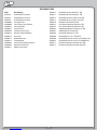
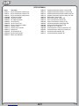
Part Number Description
LOSA5224 Certifi ed Shock Fluid 30 wt.
LOSA5225 Certifi ed Shock Fluid 35 wt.
LOSA5226 Certifi ed Shock Fluid 40 wt.
LOSA99004 Losi Cargo Bag
LOSA99006 Losi Pit Roller Carrier/Pit Boxes
LOSA99013 Losi Large Pit Mat
LOSA99015 Losi Pit Apron
LOSA99104 Losi Wrench Set US (4 pc)
LOSA99165 Aluminum Turnbuckle Wrench
LOSA99772 Camber Gauge
LOSA99173 Ride Height Gauge
LOSA99174 Car Stand
LOSA99202 Losi-Lok Threadlock, Blue
LOSA99203 High-Pressure Black Grease
LOSA99217 Nitrotec Cleaner Spray
LOSB2167 Front Shock Tower, Machined Aluminum: TEN
LOSB2171 Rear Shock Tower, Machined Aluminum: TEN
LOSB2172 Rear Shock Tower, Carbon, 4mm: TEN
LOSB2173 Front Shock Tower, Carbon, 4mm: TEN
LOSB2130 Rear Hubs, Aluminum: TEN
LOSB2223 Front Chassis Brace, Aluminum: TEN
LOSB2224 Rear Chassis Brace, Aluminum: TEN
LOSB2846 Shock Tops, Aluminum (2): TEN
LOSB2907 One-Piece Shock Standoffs: TEN
LOSB2908 Shock Collars, Aluminum (2): TEN
LOSB2909 Piston Pack (2), Ten-T, TEN-SCTE
LOSB2960 Front and Rear Spring Set (4)–Soft (Silver): 10-T
LOSB2962 Front and Rear Spring Set (4)–Firm (Gold): 10-T
LOSB4112 Adjustable Front Hinge Pin Holder Set: TEN
LOSB4113 Adjustable Rear Hinge Pin Holder Set: TEN
OPTIONAL PARTS LIST

57 - IT
57
57
57
I
I
- I
T
T
57
57
57
I
I
- I
T
T
T
1
2
3
1
2
Outside
Center
Inside
3
2
1
1
B2
Outside
Center
Inside
A
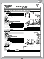
Notes
Ten-SCTE
1 degrees OUT
29.5mm
0 degree
Stock/20 degrees
2.0mm
4 holes @ 1.07mm/40 wt
Gold/Hard
85mm Center to Center
Long
Up
Position 1
Position 1 / Outside
Grease
Grease
3 degrees
2 degrees
24.5mm
-2.5 degrees
All the way back
1.8mm
4 holes @ 1.09mm/30 wt
100.8mm Center to Center
Position 2 - A
Position 2 - Inside
Grease
Losi 3.4
For increased stability, use 10000
weight oil in the front and center
differentials.
For increased traction, use 2000 weight
oil in the rear differential.
Stock
Black/Medium
10/06/10
xxxx x
Motor:
Electronics
ESC:
Battery:

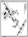
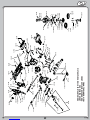
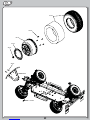
VISTA ESPLOSA DELLA PARTE POSTERIORE
REAR EXPLODED VIEW
HECK EXPLOSIONSZEICHNUNG
VUE ÉCLATÉE ARRIÈRE
A6302
B3578
B3578
B2213
A6947
B2278
A6271
B2211
A6302
A6947
B3572
B3104
A6278
A6282
B2170
A6229
B2414
A8200
A6236
A6278
B2022
B2417
B2417
A6278
B2414
B2213
A6256
A6278
A6302
A6272
B3104
B4023
A6302 B4022
A6279
B2222
A6957
A6302
B4109
A6302
B2023
A6286
A6295
B4109 B3495
A6958
B2103
A6279
B4023
B4022
B4003
B3564
B3564
A6279
B3569
A6956
A6956
B3542
B3553
B3553
B3570
B3542
B3546
B3542

59
59
59
59
59
59
59
59
59
59
59
59
59
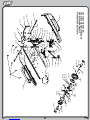
VISTA ESPLOSA DELLA PARTE ANTERIORE
FRONT EXPLODED VIEW
FRONT EXPLOSIONSZEICHNUNG
VUE ÉCLATÉE AVANT
B3556 B3556
B3555
A8200
A6236
B2414
A6256
A6282
B3571
B2278
B2213
B2211
A6275
A6275
A6302
A6947
A6947 B4023
B4022
B4003
B4023
B4022
B3495
A6302
B4109
A6302
A6282
B2100
A6295
B2222
B2222
B3104
A6278
A6957
B2021
A6286
B2021
B4109
A6275
A6272
B2421
B2421
A6278
A6277
A6302
B2906
A6302
A6227
B2211
B2213
A6240
A6240
A6290
A6958
B2100
B2100
B2100
B4022
A6272
B3564
B3574
B3564
B3104
B2163
A6229
A6286
B3563
B3563
B3568
B3542
B3563
B3568
B3569
B3542
B3563
B3568
B3563
B3542
B3572
Rear
B3571
Front
B3542
A6956
B3563
B3568

60
60
60
60
60
60
60
60
60
60
60
60
60
60
60
60
60
60
60
60
60
60
60
60
60
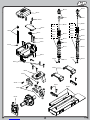
VISTA ESPLOSA DEL TELAIO
CHASSIS EXPLODED VIEW
CHASSIS EXPLOSIONSZEICHNUNG
VUE ÉCLATÉE DU CHÂSSIS
B2124
B2123
A6275
B2123
B2124
A6907
B2278
A6302
B2419
A6306
A6275
A6907
A2278
A6302
A6256
B4210
A4210
B4023
B4210
A6306
A6256
B4210
A6278
A6277
B2124
B4022
A6907
B4023
B4003
A6270
B2279
B2279
B2279
B2411
A6271B4022
A6270
A6271
A6270
B2419
B2123
A6907
B2124
B3553
B3568
A6956
B3570
B3542
B3436
A6956
B3553
B3542
B3568
B3542
B3568
B3553
B3542
B3569
B3542
B3553
B3553
B3568
B3542
B3542


La page est en cours de chargement...
La page est en cours de chargement...
La page est en cours de chargement...
La page est en cours de chargement...
La page est en cours de chargement...
La page est en cours de chargement...
La page est en cours de chargement...
La page est en cours de chargement...
La page est en cours de chargement...
La page est en cours de chargement...
La page est en cours de chargement...
La page est en cours de chargement...
La page est en cours de chargement...
La page est en cours de chargement...
La page est en cours de chargement...
La page est en cours de chargement...
La page est en cours de chargement...
La page est en cours de chargement...
La page est en cours de chargement...
La page est en cours de chargement...
La page est en cours de chargement...
La page est en cours de chargement...
La page est en cours de chargement...
La page est en cours de chargement...
La page est en cours de chargement...
La page est en cours de chargement...
La page est en cours de chargement...
La page est en cours de chargement...
La page est en cours de chargement...
La page est en cours de chargement...
La page est en cours de chargement...
La page est en cours de chargement...
La page est en cours de chargement...
La page est en cours de chargement...
La page est en cours de chargement...
La page est en cours de chargement...
La page est en cours de chargement...
La page est en cours de chargement...
La page est en cours de chargement...
La page est en cours de chargement...
La page est en cours de chargement...
La page est en cours de chargement...
La page est en cours de chargement...
La page est en cours de chargement...
La page est en cours de chargement...
La page est en cours de chargement...
La page est en cours de chargement...
La page est en cours de chargement...
La page est en cours de chargement...
La page est en cours de chargement...
La page est en cours de chargement...
La page est en cours de chargement...
La page est en cours de chargement...
La page est en cours de chargement...
La page est en cours de chargement...
La page est en cours de chargement...
La page est en cours de chargement...
La page est en cours de chargement...
La page est en cours de chargement...
La page est en cours de chargement...
La page est en cours de chargement...
La page est en cours de chargement...
La page est en cours de chargement...
La page est en cours de chargement...
-
 1
1
-
 2
2
-
 3
3
-
 4
4
-
 5
5
-
 6
6
-
 7
7
-
 8
8
-
 9
9
-
 10
10
-
 11
11
-
 12
12
-
 13
13
-
 14
14
-
 15
15
-
 16
16
-
 17
17
-
 18
18
-
 19
19
-
 20
20
-
 21
21
-
 22
22
-
 23
23
-
 24
24
-
 25
25
-
 26
26
-
 27
27
-
 28
28
-
 29
29
-
 30
30
-
 31
31
-
 32
32
-
 33
33
-
 34
34
-
 35
35
-
 36
36
-
 37
37
-
 38
38
-
 39
39
-
 40
40
-
 41
41
-
 42
42
-
 43
43
-
 44
44
-
 45
45
-
 46
46
-
 47
47
-
 48
48
-
 49
49
-
 50
50
-
 51
51
-
 52
52
-
 53
53
-
 54
54
-
 55
55
-
 56
56
-
 57
57
-
 58
58
-
 59
59
-
 60
60
-
 61
61
-
 62
62
-
 63
63
-
 64
64
-
 65
65
-
 66
66
-
 67
67
-
 68
68
-
 69
69
-
 70
70
-
 71
71
-
 72
72
-
 73
73
-
 74
74
-
 75
75
-
 76
76
-
 77
77
-
 78
78
-
 79
79
-
 80
80
-
 81
81
-
 82
82
-
 83
83
-
 84
84


Team Losi TEN-SCTE Instructions Manual
- Catégorie
- Jouets télécommandés
- Taper
- Instructions Manual
dans d''autres langues
- italiano: Team Losi TEN-SCTE
- English: Team Losi TEN-SCTE
Autres documents
-
Team Losi Racing TLR04011 Le manuel du propriétaire
-
-
-
 Force RC FCES04001 Le manuel du propriétaire
-
-
Losi LOS03041 Le manuel du propriétaire
-
Losi LOS05014T2 Le manuel du propriétaire
-
-
-
