Hitachi M 12VE Instruction And Safety Manual
- Catégorie
- Outils électroportatifs
- Taper
- Instruction And Safety Manual

Model
Modèle
Modelo
M 12VE
Router
Détoureuse
Fresadora
SAFETY INSTRUCTIONS AND INSTRUCTION MANUAL
WARNING
IMPROPER OR UNSAFE use of this power tool can result in death or serious bodily injury!
This manual contains important information about product safety. Please read and
understand this manual BEFORE operating the power tool. Please keep this manual
available for other users and owners before they use the power tool. This manual should be
stored in safe place.
INSTRUCTIONS DE SECURITE ET MODE D’EMPLOI
AVERTISSEMENT
Une utilisation INCORRECTE OU DANGEREUSE de cet outil motorisé peut entraîner la
mort ou de sérieuses blessures corporelles !
Ce mode d’emploi contient d’importantes informations à propos de la sécurité de ce produit.
Prière de lire et de comprendre ce mode d’emploi AVANT d’utiliser l’outil motorisé. Garder ce
mode d’emploi à la disponibilité des autres utilisateurs et propriétaires avant qu’ils utilisent
l’outil motorisé. Ce mode d’emploi doit être conservé dans un endroit sûr.
INSTRUCCIONES DE SEGURIDAD Y MANUAL DE INSTRUCCIONES
ADVERTENCIA
¡La utilización INAPROPIADA O PELIGROSA de esta herramienta eléctrica puede resultar
en lesiones de gravedad o la muerte!
Este manual contiene información importante sobre la seguridad del producto. Lea y
comprenda este manual ANTES de utilizar la herramienta eléctrica. Guarde este manual
para que puedan leerlo otras personas antes de utilizar la herramienta eléctrica. Este
manual debe ser guardado en un lugar seguro.
DOUBLE INSULATION
DOUBLE ISOLATION
AISLAMIENTO DOBLE

English
Page Page
Français
Page Page
Español
Página Página
CONTENTS
TABLE DES MATIÈRES
ÍNDICE
IMPORTANT SAFETY INSTRUCTIONS ..............3
MEANINGS OF SIGNAL WORDS ........................3
SAFETY...................................................................3
GENERAL POWER TOOL SAFETY
WARNINGS ...................................................3
SPECIFIC SAFETY RULES AND SYMBOLS .......4
DOUBLE INSULATION FOR SAFER
OPERATION ..................................................5
USE OF EXTENSION CORD ................................6
FUNCTIONAL DESCRIPTION ...............................7
NAME OF PARTS .................................................7
SPECIFICATIONS ................................................7
ASSEMBLY AND OPERATION ..............................8
APPLICATIONS ....................................................8
PRIOR TO OPERATION .......................................8
INSTALLING AND REMOVING BITS ...................8
HOW TO USE THE ROUTER ...............................9
USING THE OPTIONAL ACCESSORIES ...........11
MAINTENANCE AND INSPECTION ....................12
ACCESSORIES ....................................................12
STANDARD ACCESSORIES .............................12
OPTIONAL ACCESSORIES (sold separately) ....12
PARTS LIST ..........................................................40
CONSIGNES DE SÉCURITÉ IMPORTANTES ...14
SIGNIFICATION DES MOTS
D’AVERTISSEMENT....................................14
SÉCURITÉ ............................................................14
AVERTISSEMENTS DE SÉCURITÉ
GÉNÉRAUX CONCERNANT LES
OUTILS ÉLECTRIQUES ..............................14
REGLES DE SECURITE SPECIFIQUES ET
SYMBOLES .................................................16
DOUBLE ISOLATION POUR UN
FONCTIONNEMENT PLUS SUR.................17
UTILISATION D’UN CORDON DE
RALLONGE..................................................18
DESCRIPTION FONCTIONNELLE ......................19
NOM DES PARTIES ...........................................19
SPECIFICATIONS ..............................................19
ASSEMBLAGE ET FONCTIONNEMENT .............20
APPLICATIONS ..................................................20
AVANT L’UTILISATION ......................................20
INSTALLATION ET RETRAIT DE LA MECHE ....20
UTILISATION DE DETOUREUSE ......................21
UTILISATION DES ACCESSOIRES EN
OPTION .......................................................24
ENTRETIEN ET INSPECTION .............................25
ACCESSOIRES ....................................................25
ACCESSOIRES STANDARD .............................25
ACCESSOIRES SUR OPTION
(vendus séparément) ...................................26
LISTE DES PIÈCES ..............................................40
INSTRUCCIONES IMPORTANTES SOBRE
SEGURIDAD ................................................27
SIGNIFICADO DE LAS PALABRAS DE
SEÑALIZACIÓN ...........................................27
SEGURIDAD .........................................................27
ADVERTENCIAS DE SEGURIDAD
GENERAL DE LA HERRAMIENTA
ELÉCTRICA .................................................27
NORMAS Y SÍMBOLOS ESPECÍFICOS DE
SEGURIDAD ................................................29
AISLAMIENTO DOBLE PARA OFRECER
UNA OPERACIÓN MÁS SEGURA ..............30
UTILIZACIÓN DE UN
CABLE PROLONGADOR ............................31
DESCRIPCIÓN FUNCIONAL ...............................32
NOMENCLATURA ..............................................32
ESPECIFICACIONES .........................................32
MONTAJE Y OPERACIÓN ...................................33
APLICACIONES .................................................33
ANTES DE LA OPERACIÓN...............................33
INSTALACIÓN Y EXTRACCIÓN DE LAS
BROCAS ......................................................33
CÓMO USAR LA FRESADORA .........................34
UTILIZACION DE LOS ACCESORIOS
OPCIONALES ..............................................37
MANTENIMIENTO E INSPECCIÓN .....................38
ACCESORIOS ......................................................38
ACCESORIOS ESTÁNDAR ................................38
ACCESORIOS OPCIONALES
(de venta por separado) ...............................39
LISTA DE PIEZAS ................................................40

3
English
IMPORTANT SAFETY INSTRUCTIONS
Read and understand all of the safety precautions, warnings and operating instructions in the instruction
manual before operating or maintaining this power tool.
Most accidents that result from power tool operation and maintenance are caused by the failure to observe
basic safety rules or precautions. An accident can often be avoided by recognizing a potentially hazardous
situation before it occurs, and by observing appropriate safety procedures.
Basic safety precautions are outlined in the “SAFETY” section of this instruction manual and in the sections
which contain the operation and maintenance instructions.
Hazards that must be avoided to prevent bodily injury or machine damage are identifi ed by WARNINGS on
the power tool and in this instruction manual.
Never use this power tool in a manner that has not been specifi cally recommended by HITACHI.
MEANINGS OF SIGNAL WORDS
WARNING indicates a potentially hazardous situations which, if ignored, could result in death or serious
injury.
CAUTION indicates a potentially hazardous situations which, if not avoided, may result in minor or moderate
injury, or may cause machine damage.
NOTE emphasizes essential information.
SAFETY
GENERAL POWER TOOL SAFETY WARNINGS
WARNING
Read all safety warnings and instructions.
Failure to follow the warnings and instructions may result in electric shock, fi re and/or serious injury.
Save all warnings and instructions for future reference.
The term “power tool” in the warnings refers to your mains-operated (corded) power tool or battery-
operated (cordless) power tool.
1) Work area safety
a) Keep work area clean and well lit.
Cluttered or dark areas invite accidents.
b) Do not operate power tools in explosive
atmospheres, such as in the presence of
fl ammable liquids, gases or dust.
Power tools create sparks which may ignite
the dust of fumes.
c) Keep children and bystanders away
while operating a power tool.
Distractions can cause you to lose control.
2) Electrical safety
a) Power tool plugs must match the outlet.
Never modify the plug in any way.
Do not use any adapter plugs with
earthed (grounded) power tools.
Unmodifi ed plugs and matching outlets will
reduce risk of electric shock.
b) Avoid body contact with earthed or
grounded surfaces such as pipes,
radiators, ranges and refrigerators.
There is an increased risk of electric shock if
your body is earthed or grounded.
c) Do not expose power tools to rain or wet
conditions.
Water entering a power tool will increase the
risk of electric shock.
d) Do not abuse the cord. Never use the
cord for carrying, pulling or unplugging
the power tool.
Keep cord away from heat, oil, sharp
edges or moving parts.
Damaged or entangled cords increase the
risk of electric shock.
e) When operating a power tool outdoors,
use an extension cord suitable for
outdoor use.

4
English
Use of a cord suitable for outdoor use
reduces the risk of electric shock.
f) If operating a power tool in a damp
location is unavoidable, use a residual
current device (RCD) protected supply.
Use of an RCD reduces the risk of electric
shock.
3) Personal safety
a) Stay alert, watch what you are doing and
use common sense when operating a
power tool.
Do not use a power tool while you are
tired or under the infl uence of drugs,
alcohol or medication.
A moment of inattention while operating
power tools may result in serious personal
injury.
b) Use personal protective equipment.
Always wear eye protection.
Protective equipment such as dust mask,
non-skid safety shoes, hard hat, or hearing
protection used for appropriate conditions
will reduce personal injuries.
c) Prevent unintentional starting. Ensure
the switch is in the off -position before
connecting to power source and/or
battery pack, picking up or carrying the
tool.
Carrying power tools with your fi nger on the
switch or energising power tools that have
the switch on invites accidents.
d) Remove any adjusting key or wrench
before turning the power tool on.
A wrench or a key left attached to a rotating
part of the power tool may result in personal
injury.
e) Do not overreach. Keep proper footing
and balance at all times.
This enables better control of the power tool
in unexpected situations.
f) Dress properly. Do not wear loose
clothing or jewellery. Keep your hair,
clothing and gloves away from moving
parts.
Loose clothes, jewellery or long hair can be
caught in moving parts.
g) If devices are provided for the connection
of dust extraction and collection
facilities, ensure these are connected
and properly used.
Use of dust collection can reduce dust-
related hazards.
4) Power tool use and care
a) Do not force the power tool. Use the
correct power tool for your application.
The correct power tool will do the job
better and safer at the rate for which it was
designed.
b) Do not use the power tool if the switch
does not turn it on and off .
Any power tool that cannot be controlled
with the switch is dangerous and must be
repaired.
c) Disconnect the plug from the power
source and/or the battery pack from
the power tool before making any
adjustments, changing accessories, or
storing power tools.
Such preventive safety measures reduce the
risk of starting the power tool accidentally.
d) Store idle power tools out of the reach
of children and do not allow persons
unfamiliar with the power tool or these
instructions to operate the power tool.
Power tools are dangerous in the hands of
untrained users.
e) Maintain power tools. Check for
misalignment or binding of moving
parts, breakage of parts and any other
condition that may aff ect the power tool’s
operation.
If damaged, have the power tool repaired
before use.
Many accidents are caused by poorly
maintained power tools.
f) Keep cutting tools sharp and clean.
Properly maintained cutting tools with sharp
cutting edges are less likely to bind and are
easier to control.
g) Use the power tool, accessories and
tool bits etc. in accordance with these
instructions, taking into account the
working conditions and the work to be
performed.
Use of the power tool for operations diff erent
from those intended could result in a
hazardous situation.
5) Service
a) Have your power tool serviced by a
qualifi ed repair person using only
identical replacement parts.
This will ensure that the safety of the power
tool is maintained.
SPECIFIC SAFETY RULES AND
SYMBOLS
1. Hold power tools by insulated gripping
surfaces when performing an operation
where the cutting tool may contact hidden
wiring or its own cord.

5
English
Contact with a “live” wire will make exposed
metal parts of the tool “live” and shock the
operator.
2. Use clamps or another practical way to
secure and support the workpiece to a
stable platform.
Holding the work by hand or against your body
leaves it unstable and may lead to loss of
control.
3. Always wear ear protectors when using the
tool for extended periods.
Prolonged exposure to high intensity
noise can cause hearing loss.
4. Handle the bits very carefully.
5. Check the bit carefully for cracks or damage
before operation. Replace cracked or
damaged bit immediately.
6. Avoid cutting nails. Inspect for and
remove all nails from the workpiece before
operation.
7. Hold the tool fi rmly with both hands.
8. Keep hands away from rotating parts.
9. Make sure the bit is not contacting the
workpiece before the switch is turned on.
10. Before using the tool on an actual workpiece,
let it run for a while. Watch for vibration or
wobbling that could indicate improperly
installed bit.
11. Be careful of the bit rotating direction and
the feed direction.
12. Do not leave the tool running. Operate the
tool only when hand-held.
13. Always switch off and wait for the bit to
come to a complete stop before removing
the tool from workpiece.
14. Do not touch the bit immediately after
operation: it may be extremely hot and
could burn your skin.
15. Always lead the power supply cord away
from the tool towards the rear.
16. After changing the bits or making any
adjustments, make sure the collet nut and
any other adjustment devices are securely
tightened.
Loose adjustment device can unexpectedly
shift, causing loss of control, loose rotating
components will be violently thrown.
17. Always wear eye protection that meets the
requirement of the latest revision
of ANSI Standard Z87.1.
18. Defi nitions for symbols used on this tool
V ............ volts
Hz .......... hertz
A ............ amperes
........... no load speed
W ........... watt
.......... Class II Construction
---/min ... revolutions or reciprocation per
minute
.......... A lter na tin g cu rr ent
DOUBLE INSULATION FOR SAFER
OPERATION
To ensure safer operation of this power tool, HITACHI
has adopted a double insulation design. “Double
insulation” means that two physically separated
insulation systems have been used to insulate the
electrically conductive materials connected to the
power supply from the outer frame handled by the
operator. Therefore, either the symbol “ ” or the
words “Double insulation” appear on the power tool
or on the nameplate.
Although this system has no external grounding,
you must still follow the normal electrical safety
precautions given in this Instruction Manual,
including not using the power tool in wet
environments.
To keep the double insulation system eff ective,
follow these precautions:
○ Only Hitachi Authorized Service Center should
disassemble or assemble this power tool, and
only genuine HITACHI replacement parts should
be installed.
○ Clean the exterior of the power tool only with a
soft cloth moistened with soapy water, and dry
thoroughly.
Never use solvents, gasoline or thinners on
plastic components; otherwise the plastic may
dissolve.

6
English
USE OF EXTENSION CORD
Make sure your extension cord is in good condition. When using an extension cord, be sure to use one
heavy enough to carry the current your product will draw.
An undersized cord will cause a drop in line voltage resulting in loss of power and overheating. Table shows
the correct size to use depending on cord length and nameplate ampere rating. If in doubt, use the next
heavier gage. The smaller the gage number, the heavier the cord.
MINIMUM GAGE FOR CORD SETS
Total Length of Cord in Feet (Meter)
0 – 25 26 – 50 51 – 100 101 – 150
(0 – 7.6) (7.9 – 15.2) (15.5 – 30.5) (30.8 – 45.7)
Ampere rating AWG
More Not more
than than
0 – 6 18 16 16 14
6 – 10 18 16 14 12
10 – 12 16 16 14 12
12 – 16 14 12 Not recommended
WARNING
Avoid electrical shock hazard. Never use this tool with a damaged or frayed electrical cord or
extension cord.
Inspect all electrical cords regularly. Never use in or near water or in any environment where
electric shock is possible.
SAVE THESE INSTRUCTIONS
AND
MAKE THEM AVAILABLE TO
OTHER USERS
AND
OWNERS OF THIS TOOL!

7
English
FUNCTIONAL DESCRIPTION
NOTE
The information contained in this instruction manual is designed to assist you in the safe operation and
maintenance of the power tool.
Never operate, or attempt any maintenance on the tool unless you have fi rst read and understood all
safety instructions contained in this manual.
Some illustrations in this instruction manual may show details or attachments that diff er from those on
your own power tool.
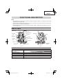
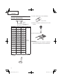
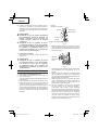
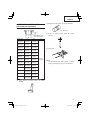
NAME OF PARTS
Fig. 1-1 Fig. 1-2
SPECIFICATIONS
Motor Single Phase, Series Commutator Motor
Power source Single Phase 120 V AC 60 Hz
Collet chuck capacity 1/2″ (12.7 mm), 1/4″ (6.35 mm)
Main body stroke 2 – 9/16″ (65 mm)
Current 15 A
No-load speed 8,000/min – 22,000/min
Weight (without cord) 12.1 lbs (5.5 kg)
Stopper
pole
Wing bolt
Stopper
block
Base
Sub base
Head cover
Lock lever
Nuts
Threaded
column
Housing
Lever
Dial
Handle
End bracket
Lock pin
Collet chuck

8
English
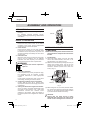
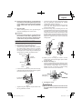
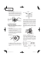
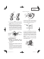
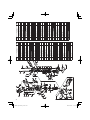
Fig. 2
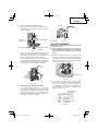
INSTALLING AND REMOVING BITS
WARNING
Be sure to switch power OFF and disconnect
the plug from the receptacle to avoid serious
trouble.
1. Installing bits
(1) Clean and insert shank of bit into the collet
chuck until shank bottoms, then back it out
approximately 1/16″ (approx. 2 mm).
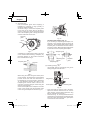
(2) With the bit inserted and pressing the lock pin
holding the armature shaft, use the 23 mm
wrench to fi rmly tighten the collet chuck in a
clockwise direction (viewed from under the
router). (Fig. 3)
Lock pin
Wrench
Loosen
Tighten
Fig. 3
(3) When using the 1/4″ (6.35 mm) diameter shank
bit, replace the equipped collet chuck with the
one for 1/4″ (6.35 mm) diameter shank bit which
is provided as the standard accessory.
CAUTION
● Ensure that the collet chuck is fi rmly
tightened after inserting a bit. Failure to do
so will result in damage to the collet chuck.
Handle
ASSEMBLY AND OPERATION
APPLICATIONS
○ Woodworking jobs centered on grooving and
beveling.
For example, grooving beveling, cutting,
copying, engraving, shape cutting, combinations
and others.
PRIOR TO OPERATION
1. Power source
Ensure that the power source to be utilized
conforms to the power source requirements
specifi ed on the product nameplate.
2. Power switch
Ensure that the switch is in the OFF position.
If the plug is connected to a receptacle while
the switch is in the ON position, the power tool
will start operating immediately and can cause
serious injury.
3. Extension cord
When the work area is far away from the power
source, use an extension cord of suffi cient
thickness and rated capacity. The extension
cord should be kept as short as practicable.
WARNING
Damaged cord must be replaced or
repaired.
4. Check the receptacle
If the receptacle only loosely accepts the plug,
the receptacle must be repaired. Contact
a licensed electrician to make appropriate
repairs.
If such a fautly receptacle is used, it may cause
overheating, resulting in a serious hazard.
5. Confi rming condition of the environment
Confi rm that the work site is placed under
appropriate conditions conforming to prescribed
precautions.
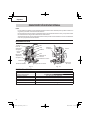
6. Setting the attachment angle of the handle
As Fig. 2 shows, the handle attachment angle
can beset in three stages. Use a plus head
screwdriver toloosen the machine screw
attached to the handle, adjust the handle to
the desired position and retighten the machine
screw.

9
English
5 Loosen wing bolt, and raise until indicator aligns
with the graduation representing the desired
cutting depth. Tighten wing bolt.
6 Loosen the lock lever and press the tool body
down until the stopper block to obtain the
desired cutting depth.
(2) As shown in Fig. 6 (a), loosening the two nuts
on the threaded column and moving them down
will allow you to move down to the end position
of the bit when the lock lever was loosened. This
is helpful when moving the router to align the bit
with the cutting position. As shown in Fig. 6 (b),
tighten the upper and lower nuts to secure the
cutting depth.
Fig. 6
(3) When you are not using the scale to set the
cutting depth, push up the stopper pole so that it
is not in the way.
2. Stopper block (Fig. 7)
The 2 cut-depth setting screws attached to the
stopper block can be adjusted to simultaneously
set 3 diff erent cutting depth. Use a wrench to
tighten the nuts so that the cut-depth setting
screws do not come loose at this time.
Fig. 7
3. Guiding the router
WARNING
Be sure to switch power OFF and disconnect
the plug from the receptacle to avoid serious
trouble.
● Ensure that the lock pin is not inserted into
the armature shaft after tightening the collet
chuck. Failure to do so will result in damage
to the collet chuck, lock pin and armature
shaft.
2. Removing bits
When removing the bits, do so by following the
steps for installing bits in reverse order.
CAUTION
Ensure that the lock pin is not inserted into
the armature shaft after tightening a bit.
Failure to do so will result in damage to the
collet chuck, lock pin and armature shaft.
HOW TO USE THE ROUTER
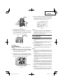
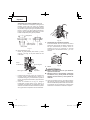
1. Adjusting depth of cut
(1) Use stopper pole to adjust depth of cut.
1 Place the tool on a fl at wood surface.
2 Turn the stopper block so that section to which
the cutting depth setting screw on a stopper
block is not attached comes to the bottom of
the stopper pole. Loosen wing bolt allowing the
stopper pole to contact with stopper block.
Fig. 4
3 Loosen the lock lever and press the tool body
until the bit just touches the fl at surface. Tighten
the lock lever at this point. (Fig. 5)
Fig. 5
4 Tighten wing bolt. Align the depth indicator with
the “0” graduation of scale.
Stopper pole
Scale
Stopper
block
Depth
indicator
Wing bolt
Loosen the
lock lever
Nuts
Threaded
column
(b)(a)
Cut depth
setting screw

10
English
(1) Template guide
Use the template guide when employing a
template for producing a large quantity of
identically shaped products.
As shown in Fig. 8, secure the template guide
to the base of the router with two accessory
screws. At this time, ensure that the projection
side of the template guide is facing the bottom
surface of the base of the router.
Fig. 8
A template is a profi ling mold made of plywood
or thin lumber. When making a template, pay
particular attention to the matters cescribed
blow and illustrated in Fig. 9.
Fig. 9
When using the router along the interior plane
of the template, the dimensions of the fi nished
product will be less than the dimensions of
the template by an amount equal to dimension
“A”, the diff erence between the radius of the
template guide and the radius of the bit. The
reverse is frue when using the router along the
exterior of the template.
Secure the template to the workpiece. Feed the
router in the manner that the template guide
moves along the template as shown in Fig. 10.
Fig. 10
Template guide adaptor (Fig. 11)
If you are using a template guide adapter, it is
possible to use template guides produced by
other fi rms. The template guide adaptor, like the
template guide, is attached to the base with two
accessory screws. Attach template guides made
by other fi rms to the template guide adaptor.
Fig. 11
(2) Parallel guide (Fig. 12)
Use parallel guide for chamfering and groove
cutting along the materials side.
Fig. 12
1 Insert the guide bar into the hole in the base,
adjust the distance between the bit and the
guide surface, and then fi rmly tighten the wing
bolt (A) (standard accessories).
2 As shown in Fig. 13, securely attach the bottom
of the base to processed surface of the materials.
Feed the router while keeping the guide plane
on the surface of the materials.
Template
guide
Screw
Bit
Template guide
Template
Template guide
adaptor
Template guide
Template
guide
Template guide
Guide bar
Parallel guide
Guide plane
Wing bolt (A)
A

11
English
Fig. 13
4. Adjusting the rotation speed
The M12VE has an electronic control system
that allows stepless rpm changes. As shown in
Fig. 14, dial position “1” is for minimum speed,
and position “6” for maximum speed.
Fig. 14
5. Cutting
WARNING
● Wear eye protection when operating this
tool.
● Keep your hands, face and other body parts
away from the bits and any other rotating
parts, while operating the tool.
(1) As shown in Fig. 15, remove the bit from the
work pieces and press the switch lever up to the
ON position. Do not start cutting operation until
the bit has reached full rotating speed.
Fig. 15
(2) The bit rotates clockwise (arrow direction
indicated on the base). To obtain maximum cutting
eff ectiveness, feed the router in conformance
with the feed directions shown in Fig. 16.
Fig. 16
NOTE
If a worn bit is used to make deep grooves, a
high pitched cutting noise may be produced.
Replacing the worn bit with a new one will
eliminate the high pitched noise.
USING THE OPTIONAL
ACCESSORIES
(1) Dust collector set
Connect the dust collector set cleaner to collect
dust.
For installation methods, please refer to the
handling instructions that came with the set.
(2) Fine adjustment knob
Connect the fi ne adjustment knob to adjust the
depth of cut fi nely.
For installation methods, please refer to the
handling instructions that came with the set.
NOTE
○ Moving the tool forward fast may cause a poor
quality of cut, or damage to the bit or motor.
Moving the tool forward too slowly may burn and
mar the cut.
The proper feed rate will depend on the bit size,
the kind of workpiece and depth of cut. Before
beginning the cut on the actual workpiece, it is
advisable to make a sample cut on a piece of
scrap lumber. This will show exactly how the
cut will look as well as enable you to check
dimensions.
○ Abnormalities and overloads will trigger the
overload protector, and stop operation. Remove
the load immediately, and turn the power off , then
on. The rotation speed should return to normal.
○ Do not use a power generator as the power
source. It may cause the rotation speed to
fl uctuate.
○ When using the straight guide, be sure to install it
on the right side in the feed direction. This will help
to keep it fl ush with the side of the workpiece.
Dial
Separate
Router feed
Rotation of bit
Router feed
Workpiece

12
English
STANDARD ACCESSORIES
(1) 1/4″ Collect chuck (Code No. 323293) ............. 1
(2)
Template guide adaptor (Code No. 325224).........1
(3) Template guide (Code No. 956790) .................. 1
(4) Wing bolt (Code No. 301806) ............................ 2
(5) 23 mm Wrench (Code No. 323295) ..................1
(6) Parallel guide .................................................... 1
(7) Case ................................................................. 1
1. Inspecting the screws
Regularly inspect all screws and ensure that they
are fully tightened. Should any of the screws be
loosened, retighten them immediately.
WARNING
Using this router with loosened screws is
extremely dangerous.
2. Maintenance of the motor
The motor unit winding is the very “heart” of
the power tool. Exercise due care to ensure the
winding does not become damaged and/or wet
with oil or water.
3. Service and repairs
All quality power tools will eventually require
servicing or replacement of parts because
of wear from normal use. To assure that only
authorized replacement parts will be used, all
service and repairs must be performed by a
HITACHI AUTHORIZED SERVICE CENTER,
ONLY.
ACCESSORIES
WARNING
Always use only authorized HITACHI replacement parts and accessories. Never use replacement
parts or accessories which are not intended for use with this tool. Contact HITACHI if you are
not sure whether it is safe to use a particular replacement part or accessory with your tool.
The use of any other attachment or accessory can be dangerous and could cause injury or
mechanical damage.
NOTE
Accessories are subject to change without any obligation on the part of the HITACHI.
MAINTENANCE AND INSPECTION
WARNING
Be sure to switch power OFF and disconnect the plug from the receptacle during maintenance
and inspection.
OPTIONAL ACCESSORIES
(sold separately)
(1) Template guide
Bottom of sub base
4. Service parts list
CAUTION
Repair, modifi cation and inspection of
Hitachi Power Tools must be carried out by
a Hitachi Authorized Service Center.
This Parts List will be helpful if presented
with the tool to the Hitachi Authorized
Service Center when requesting repair or
other maintenance.
In the operation and maintenance of power
tools, the safety regulations and standards
prescribed in each country must be
observed.
MODIFICATIONS
Hitachi Power Tools are constantly being
improved and modifi ed to incorporate the latest
technological advancements.
Accordingly, some parts may be changed
without prior notice.

13
English
Code No. A B C
303 347
19/64″
(7.5 mm)
3/8″
(9.5 mm)
3/16″
(4.5 mm)
303 348
5/16″
(8 mm)
25/64"
(10 mm)
303 349
23/64″
(9 mm)
7/16″
(11.1 mm)
303 350
25/64″
(10 mm)
15/32″
(12 mm)
303 351
27/64″
(10.7 mm)
1/2″
(12.7 mm)
303 352
15/32″
(12 mm)
35/64″
(14 mm)
303 353
35/64″
(14 mm)
5/8″
(16 mm)
956 790
21/32″
(16.5 mm)
45/64″
(18 mm)
956 932Z
47/64″
(18.5 mm)
25/32″
(20 mm)
303 354
57/64″
(22.5 mm)
15/16″
(24 mm)
956 933Z
1″
(25.5 mm)
1-1/16″
(27 mm)
956 934Z
1-1/8″
(28.5 mm)
1-3/16″
(30 mm)
303 355
1-33/64″
(38.5 mm)
1-37/64″
(40 mm)
(2) Dust collector set (Code No. 997466)
(3) Chuck sleeve (Code No. 956928Z)
3/8″ (9.5 mm)
(4) Fine adjustment knob (Code No. 318304)
(5) Straight guide
NOTE
Specifi cations are subject to change without
any obligation on the part of the HITACHI.

14
Français
CONSIGNES DE SÉCURITÉ IMPORTANTES
Lire et comprendre toutes les précautions de sécurité, les avertissements et les instructions de
fonctionnement dans ce mode d’emploi avant d’utiliser ou d’entretenir cet outil motorisé.
La plupart des accidents causés lors de l’utilisation ou de l’entretien de l’outil motorisé proviennent d’un non
respect des règles ou précautions de base de sécurité. Un accident peut la plupart du temps être évité si
l’on reconnaît une situation de danger potentiel avant qu’elle ne se produise, et en observant les procédures
de sécurité appropriées.
Les précautions de base de sécurité sont mises en évidence dans la section “SECURITE” de ce mode
d’emploi et dans les sections qui contiennent les instructions de fonctionnement et d’entretien.
Les dangers qui doivent être évités pour prévenir des blessures corporelles ou un endommagement de la
machine sont identifi és par AVERTISSEMENTS sur l’outil motorisé et dans ce mode d’emploi.
Ne jamais utiliser cet outil motorisé d’une manière qui n’est pas spécifi quement recommandée par
HITACHI.
SIGNIFICATION DES MOTS D’AVERTISSEMENT
AVERTISSEMENT indique des situations potentiellement dangereuses qui, si elles sont ignorées,
pourraient entraîner la mort ou de sérieuses blessures.
PRECAUTION indique des situations dangereuses potentilles qui, si elles ne sont pas évitées, peuvent
entraîner de mineures et légères blessures ou endommager la machine.
REMARQUE met en relief des informations essentielles.
SÉCURITÉ
AVERTISSEMENTS DE SÉCURITÉ GÉNÉRAUX CONCERNANT LES
OUTILS ÉLECTRIQUES
AVERTISSEMENT
Lire tous les avertissements de sécurité et les instructions
Tout manquement à observer ces avertissements et instructions peut engendrer des chocs électriques,
des incendies et/ou des blessures graves.
Conservez tous les avertissements et toutes les instructions pour vous y référer
ultérieurement.
Le terme “outil électrique”, utilisé dans les avertissements, se réfère aux outils électriques (câblé) ou
aux outils à piles (sans fi l).
1) Sécurité de l’aire de travail
a) Maintenir l’aire de travail propre et bien
éclairée.
Les endroits encombrés ou sombres sont
propices aux accidents.
b) Ne pas utiliser d’outils électriques en
présence de liquides, gaz ou poussière
infl ammables, au risque de provoquer
une explosion.
Les outils électriques créent des étincelles
susceptibles d’enfl ammer la poussière.
c) Ne pas laisser les enfants et les visiteurs
s’approcher de vous lorsque vous utiliser
un outil électrique.
Les distractions peuvent faire perdre le
contrôle.
2) Sécurité électrique
a) Les prises de l’outil électrique doivent
correspondre à la prise secteur.
Ne jamais modifi er la prise.
Ne pas utiliser d’adaptateurs avec les
outils électriques mis à la masse.
Les prises non modifi ées et les prises
secteurs correspondantes réduisent les
risques de choc électrique.
b) Eviter tout contact avec les surfaces
mises à la masse telles que les tuyaux,
radiateurs, bandes et réfrigérateurs.

15
Français
Le risque de choc électrique est accru en
cas de mise à la masse du corps.
c) Ne pas exposer les outils électriques à la
pluie ou à des conditions humides.
Si l’eau pénètre dans l’outil, cela augmente
les risques de choc électrique.
d) Ne pas utiliser le cordon à tort. Ne jamais
utiliser le cordon pour transporter ou
débrancher l’outil électrique.
Maintenir le cordon loin de la chaleur, de
l’huile, des bords pointus ou des pièces
mobiles.
Les cordons endommagés ou usés
augmentent les risques de choc électrique.
e) En cas d’utilisation d’un outil électrique à
l’extérieur, utiliser un cordon de rallonge
adapté à un usage extérieur.
L’utilisation d’un cordon adapté à l’usage
extérieur réduit les risques de choc
électrique.
f) Si vous devez utiliser un outil électrique
dans un endroit humide, utilisez une
alimentation protégée contre les
courants résiduels.
L’utilisation d’un dispositif de protection
contre les courants résiduels réduit le risque
de choc électrique.
3) Sécurité personnelle
a) Restez alerte, regarder ce que vous faites
et usez de votre bon sens en utilisant un
outil électrique.
Ne pas utiliser d’outil électrique si vous
êtes sous l’infl uence de drogues, d’alcool
ou de médicaments.
Pendant l’utilisation d’outils électrique, un
instant d’inattention peut entraîner des
blessures graves.
b) Utiliser un équipement de protection
individuelle. Toujours porter des verres
de protection.
L’utilisation d’équipements de protection
tels que les masques anti-poussière, les
chaussures de sécurité anti-dérapantes, les
casques ou les protections auditives dans
des conditions appropriées réduisent les
risques de blessures.
c) Empêcher les démarrages intempestifs.
Veiller à ce que l’interrupteur soit en
position d’arrêt avant de brancher à
une source d’alimentation et/ou une
batterie, de ramasser l’outil au sol ou de
le transporter.
Transporter les outils électriques avec le
doigt sur l’interrupteur ou brancher les outils
électriques avec l’interrupteur en position de
marche peut entraîner des accidents.
d) Retirer toute clé de sécurité ou clé avant
de mettre l’outil électrique en marche.
Laisser une clé ou une clé de sécurité sur
une partie mobile de l’outil électrique peut
engendrer des blessures.
e) Ne pas trop se pencher. Toujours garder
une bonne assise et un bon équilibre
pendant le travail.
Cela permet un meilleur contrôle de l’outil
électrique dans des situations imprévisibles.
f) Porter des vêtements adéquats. Ne pas
porter de vêtements amples ni de bijoux.
Maintenir les cheveux, les vêtements et
les gants loin des pièces mobiles.
Les vêtements amples ou les cheveux
longs peuvent se prendre dans les pièces
mobiles.
g) En cas de dispositifs destinés au
raccordement d’installations d’extraction
et de recueil de la poussière, veiller à ce
qu’ils soient correctement raccordés et
utilisés.
L’utilisation d’un dispositif de collecte de la
poussière peut réduire les dangers associés
à la poussière.
4) Utilisation et entretien d’un outil électrique
a) Ne pas forcer sur l’outil électrique.
Utiliser l’outil électrique adapté à vos
travaux.
Le bon outil électrique fera le travail mieux et
en toute sécurité au régime pour lequel il a
été conçu.
b) Ne pas utiliser l’outil électrique si
l’interrupteur ne le met pas en position
de marche et d’arrêt.
Tout outil ne pouvant être contrôlé par
l’interrupteur est dangereux et doit être
réparé.
c) Débrancher la prise ou retirer la batterie
avant de procéder à des réglages, au
remplacement des accessoires ou au
stockage des outils électriques.
Ces mesures préventives de sécurité
réduisent les risques de démarrage
accidentel de l’outil électrique.
d) Stockez les outils électriques inutilisés
hors de la portée des enfants et ne pas
laisser des personnes non familiarisées
avec l’outil ou ces instructions utiliser
l’outil électrique.
Les outils électriques sont dangereux entre
les mains d’utilisateurs non habilités.
e) Entretenir les outils électriques. Vérifi er
l’absence de mauvais alignement ou
d’arrêt, d’endommagement de pièces

16
Français
ou toute autre condition susceptible
d’aff ecter l’opération de l’outil.
Si l’outil est endommagé, le faire réparer
avant utilisation.
De nombreux accidents sont dus à des outils
mal entretenus.
f) Maintenir les outils coupants aiguisés et
propres.
Des outils coupants bien entretenus avec
des bords aiguisés sont moins susceptibles
de se coincer et plus simples à contrôler.
g) Utiliser l’outil électrique, les accessoires
et les mèches de l’outil, etc. conformément
à ces instructions en tenant compte des
conditions d’utilisation et du travail à
réaliser.
L’utilisation de l’outil électrique pour des
opérations diff érentes de celles pour
lesquelles il a été conçu est dangereuse.
5) Service
a) Faire entretenir l’outil électrique par un
technicien habilité à l’aide de pièces de
rechange identiques exclusivement.
Cela garantira le maintien de la sécurité de
l’outil électrique.
REGLES DE SECURITE
SPECIFIQUES ET SYMBOLES
1. Tenir les outils par les surfaces de grippage
lors de la réalisation d’opération où l’outil
de coupe risque d’entrer en contact avec
des câbles cachés ou son propre cordon.
Un contact avec un fi l “sous tension” mettra les
parties métalliques de l’outil “sous tension” et
électrocutera l’utilisateur.
2. Utiliser des dispositifs de serrage ou toutes
autres façons de fi xer et de maintenir la
pièce à usiner sur une plate-forme stable.
Tenir la pièce avec la main ou contre son corps
est instable et peut conduire à une perte de
contrôle de l’outil.
3. Toujours porter des bouchons d’oreille lors
de l’utilisation de l’outil pendant de longues
périodes.
Une exposition prolongée à un son de
forte intensité peut endommager l’ouïe
de l’utilisateur.
4. Faire extrêmement attention en manipulant
les mèches.
5. Avant l’utilisation, vérifi er soigneusement si
la mèche n’est pas fi ssurée ou endommagée.
Remplacer immédiatement toute mèche
fi ssurée ou endommagée.
6. Ne pas couper de clous. Avant le travail,
vérifi er s’il y a des clous, et les retirer le cas
échéant.
7. Tenir l’outil fermement des deux mains.
8. Ne pas approcher les mains des pièces en
mouvement.
9. S’assurer que la mèche n’est pas en contact
avec la pièce avant de mettre l’outil sous
tension.
10. Avant d’utiliser l’outil sur la pièce
proprement dite, laisser l’outil tourner
pendant quelques instants. Regarder s’il
y a des vibrations ou des irrégularités de
rotation qui signaleraient une mauvaise
installation de la mèche.
11. Faire attention au sens de rotation de la
mèche et au sens d’avance.
12. Ne pas s’éloigner de l’outil pendant qu’il
fonctionne. Toujours le tenir dans la main
quand il fonctionne.
13. Toujours éteindre l’outil et attendre que la
mèche soit complètement arrêtée avant de
retirer l’outil de la pièce.
14. Ne pas toucher la mèche tout de suite après
l’utilisation : elle risque d’être extrêmement
chaude et pourrait provoquer des brûlures.
15. Toujours acheminer le cordon d’alimentation
loin de l’outil, vers l’arrière.
16. Après avoir remplacé une mèche ou eff ectué
des réglages, s’assurer que l’écrou de
mandrin et les autres éléments de réglage
sont bien serrés à fond.
Un élément de réglage mal serré peut se
déplacer de façon inattendue, provoquant une
perte de contrôle de l’outil, et les composants
mobiles risqueraient d’être violemment éjectés.
17. Toujours porter des lunettes de protection
qui respectent les dernières
révisions du Standard ANSI Z87.1.
18. Défi nitions pour les symboles utilisés sur
cet outil
V ............ volts
Hz .......... hertz
A ............ ampères
........... vitesse sans charge
W ........... watt
.......... Construction de classe II
---/min ... rotation ou mouvements de va-et-vient
par minute
.......... C our ant alter nat if

17
Français
DOUBLE ISOLATION POUR UN
FONCTIONNEMENT PLUS SUR
Pour assurer un fonctionnement plus sûr de cet
outil motorisé, HITACHI a adopté une conception
à double insolation. “Double isolation” signifi e
que deux systèmes d’isolation physiquement
séparés ont été utilisés pour isoler les matériaux
conducteurs d’électricité connectés à l’outil motorisé
à partir du cadre extérieur manipulé par l’utilisateur.
C’est pourquoi, le symbole “
” ou les mots
“Double insulation” (double isolation) apparaissent
sur l’outil motorisé ou sur la plaque signalétique.
Bien que ce système n’ait pas de mise à terre
extérieure, il est quand même nécessaire de suivre
les précautions de sécurité électrique données dans
ce mode d’emploi, y-compris de ne pas utiliser l’outil
motorisé dans un environnement humide.
Pour garder le système de double isolation eff ectif,
suivre ces précautions:
○ Seuls le centre de service après-vente Hitachi
agréé peuvent démonter et remonter cet
outil motorisé et uniquement des pièces de
rechange HITACHI garanties d’origine doivent
être utilisées.
○ Nettoyer l’extérieur de l’outil motorisé
uniquement avec un chiff on doux légèrement
imbibé d’une solution savonneuse et essuyer
minutieusement.
Ne jamais utiliser des solvants, de l’essence ou
des diluants sur les parties en plastique; sinon
le plastique risquerait de se dissoudre.

18
Français
UTILISATION D’UN CORDON DE RALLONGE
Utiliser exclusivement un cordon de rallonge en bon état. Lorsqu’on utilise un cordon de rallonge, veiller à
ce qu’il soit suffi samment lourd pour supporter le courant dont l’appareil aura besoin.
Un cordon trop petit provoquera une chute de la tension de ligne, ce qui entraînera une perte de puissance
et une surchauff e. Le tableau indique le calibre à utiliser en fonction de la longueur du cordon et de l’intensité
nominale indiquée sur la plaque signalétique. En cas de doute, utiliser un calibre supérieur. Plus le numéro
du calibre est petit, plus le cordon est lourd.
CALIBRE MINIMUM DES CORDONS
Longueur totale de cordon en pieds (mètres)
0 – 25 26 – 50 51 – 100 101 – 150
(0 – 7.6) (7.9 – 15.2) (15.5 – 30.5) (30.8 – 45.7)
Intensité nominale CALIBRE
Supérieure Non supérieure
àà
0 – 6 18 16 16 14
6 – 10 18 16 14 12
10 – 12 16 16 14 12
12 – 16 14 12 Non recommandé
AVERTISSEMENT
Eviter tout risque de choc électrique. Ne jamais utiliser l’outil avec un cordon électrique ou un
cordon de rallonge endommagé ou dénudé.
Inspecter régulièrement les cordons électriques. Ne jamais utiliser dans l’eau ou à proximité
d’eau, ni dans un environnement susceptible de provoquer un choc électrique.
CONSERVER CES INSTRUCTIONS
ET
LES METTRE A LA DISPOSITION DES
AUTRES UTILISATEURS
ET
PROPRIETAIRES DE CET OUTIL !

19
Français
DESCRIPTION FONCTIONNELLE
REMARQUE
Les informations contenues dans ce mode d’emploi sont conçues pour assister l’utilisateur dans une
utilisation sans danger et un entretien de l’outil motorisé.
Ne jamais utiliser ni entreprendre une révision de l’outil sans avoir d’abord lu et compris toutes les
instructions de sécurité contenues dans ce manuel.
Certaines illustrations dans ce mode d’emploi peuvent montrer des détails ou des accessoires diff érents
de ceux de l’outil motorisé utilisé.
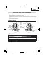
NOM DES PARTIES
Fig. 1-1 Fig. 1-2
SPECIFICATIONS
Moteur Moteur série monophasé à collecteur
Source d’alimentation Secteur 120 V AC 60 Hz, monophaséz
Capacité du mandrin de serrage 1/2″ (12.7 mm), 1/4″ (6.35 mm)
Course du corps principal 2 – 9/16″ (65 mm)
Courant 15 A
Vitesse sans charge 8,000/min – 22,000/min
Poids (sans le cordon) 12.1 lbs (5.5 kg)
Colone
d’arrêt
Boulon
papillon
Bloc d’arrêt
Socle
Socle auxiliaire
Couvercle
supérieur
Carter
Levier
Cadran
Broche d’arrêt
Etrier d’extrémité
Poignée
Mandrin à
pince
Levier de
blocage
Colonne
fi letée
Écrou

20
Français
APPLICATIONS
○ Travail du bois, essentiellement creusage de
rainures et coupes transversales.
Par exemple, creusage de rainures, coupes
transversales, coupe, duplication, burinage,
coupe à gabarit, coupes mixtes et autres.
AVANT L’UTILISATION
1. Source d’alimentation
S’assurer que la source d’alimentation qui
doit être utilisée est conforme à la source
d’alimentation requise spécifi ée sur la plaque
signalétique du produit.
2. Interrupteur d’alimentation
S’assurer que l’interrupteur est sur la position
OFF (arrêt). Si la fi che est connectée sur une
prise alors que l’interrupteur est sur la position
ON (marche), l’outil motorisé démarrera
immédiatement risquant de causer de sérieuses
blessures.
3. Cordon prolongateur
Quand la zone de travail est éloignée de la source
d’alimentation, utiliser un cordon prolongateur
d’épaisseur et de capacité nominale suffi sante.
Le cordon prolongateur doit être aussi court que
possible.
AVERTISSEMENT
Tout cordon endommagé devra être
remplacé ou réparé.
4. Vérifi er la prise
Si la prise reçoit la fi che avec beaucoup
de jeu, elle doit être réparée. Contacter un
électricien licencié pour réaliser les réparations
nécessaires.
Si une telle prise défectueuse est utilisée, elle
peut causer une surchauff e entraînant des
dangers sérieux.
5. Vérifi cation des conditions d’environnement
Vérifi er que le lieu de travail est soumis à des
conditions appropriées, conformément aux
précautions spécifi ées.
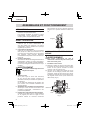
6. Réglage de l’angle d’attache de la poignée
Comme montré dans la Fig. 2, l’angle d’attache
de la poignée peut être sur réglé sur trois
positions. Utiliser un tournevis cruciforme
pour desserrer la vis sur la poignée, ajuster la
poignée sur la position désirée et resserrer la
vis.
Fig. 2
INSTALLATION ET RETRAIT DE LA
MECHE
AVERTISSEMENT
Bien mettre l’interrupteur sur OFF et
débrancher la fi che de la prise secteur pour
éviter tout ennui grave.
1. Installation de la mèche
(1) Nettoyer et insérer la queue de la mèche dans
le mandrin de serrage jusqu’à ce que la queue
touche le fond, puis la ramener en arrière
d’environ 1/16″ de pouce (2 mm).
(2) Une fois que la mèche est insérée et que la
goupille de verrouillage pressée tient l’arbre
d’armature, utiliser la clé de 23 mm pour serrer
fermement le mandrin de serrage dans le sens
des aiguilles d’une montre (vu de dessous la
détoureuse). (Fig. 3)
Fig. 3
Poignée
ASSEMBLAGE ET FONCTIONNEMENT
Broche
d’arrêt
Clef
Desserrer
Serrer
La page est en cours de chargement...
La page est en cours de chargement...
La page est en cours de chargement...
La page est en cours de chargement...
La page est en cours de chargement...
La page est en cours de chargement...
La page est en cours de chargement...
La page est en cours de chargement...
La page est en cours de chargement...
La page est en cours de chargement...
La page est en cours de chargement...
La page est en cours de chargement...
La page est en cours de chargement...
La page est en cours de chargement...
La page est en cours de chargement...
La page est en cours de chargement...
La page est en cours de chargement...
La page est en cours de chargement...
La page est en cours de chargement...
La page est en cours de chargement...
La page est en cours de chargement...
La page est en cours de chargement...
La page est en cours de chargement...
La page est en cours de chargement...
-
 1
1
-
 2
2
-
 3
3
-
 4
4
-
 5
5
-
 6
6
-
 7
7
-
 8
8
-
 9
9
-
 10
10
-
 11
11
-
 12
12
-
 13
13
-
 14
14
-
 15
15
-
 16
16
-
 17
17
-
 18
18
-
 19
19
-
 20
20
-
 21
21
-
 22
22
-
 23
23
-
 24
24
-
 25
25
-
 26
26
-
 27
27
-
 28
28
-
 29
29
-
 30
30
-
 31
31
-
 32
32
-
 33
33
-
 34
34
-
 35
35
-
 36
36
-
 37
37
-
 38
38
-
 39
39
-
 40
40
-
 41
41
-
 42
42
-
 43
43
-
 44
44


Hitachi M 12VE Instruction And Safety Manual
- Catégorie
- Outils électroportatifs
- Taper
- Instruction And Safety Manual
dans d''autres langues
- English: Hitachi M 12VE
- español: Hitachi M 12VE
Documents connexes
-
Hitachi M 12VE Handling Instructions Manual
-
Hitachi M 8V2 Manuel utilisateur
-
-
-
Hitachi M 12SC Manuel utilisateur
-
-
-
-
-