
Webasto Heating and Cooling
Installation Guide for Kit Numbers:
• 5013567A – A/C Hose Tie-In – Front Mount
• 5013568A – A/C Hose Tie-In – Rear Mount
• 5013569A – Kit AC Hose – Independent RTC UBC
Warning: Cancer and Reproductive Harm. www.P65Warnings.ca.gov
– Installation and repair of Webasto heating and cooling systems requires special Webasto
training, technical information, special tools and special equipment.
– NEVER attempt to install or repair Webasto heating or cooling system unless you have
the proper certifications, technical skills, tools, and equipment required to properly
complete the necessary procedures.
– ALWAYS carefully follow Webasto installation and repair instructions and heed all
WARNINGS.
– Webasto rejects any liability for problems and damage caused by the system being
installed by untrained personnel.

2
Contents
1.0 General Service and Safety Precautions.......................................................................................................... 3
1.1 Refrigerants and Other Chemicals ................................................................................................................. 3
1.2 System Flushing, Purging, and Pressure Testing for Leaks .............................................................................. 3
1.3 Scope ............................................................................................................................................................ 4
1.4 Applicability of Manual .................................................................................................................................. 4
1.5 Meaning of Warnings, Cautions and Notes ................................................................................................... 4
1.6 Safety ............................................................................................................................................................ 5
1.7 Legal Provisions for Installation ...................................................................................................................... 5
1.8 Prohibition on Venting .................................................................................................................................. 5
1.9 Installation General References ...................................................................................................................... 5
SPECIAL NOTES – General Installation................................................................................................................ 6
SPECIAL NOTES – Under-Chassis Condenser ...................................................................................................... 6
SPECIAL NOTES – Roof-Mounted Condenser ..................................................................................................... 7
Burgaflex Crimp Procedure ..................................................................................................................................... 8
Refrigerant Hose Layout – Tie In .............................................................................................................................. 9
VAC System Layout – Extreme ................................................................................................................................ 9
SPECIAL NOTES – Initial Start ............................................................................................................................ 10

3
INTRODUCTION
1.0 General Service and Safety Precautions
WARNING
Never service, repair, or troubleshoot this system unless you are a professional air
conditioning/refrigeration service person. Improper servicing can lead to serious injury or death from fire,
electric shock, or explosion.
Refrigeration and air conditioning devices are extremely complicated by nature. Servicing, repairing, and
troubleshooting these products should be done only by those with the necessary knowledge, training,
and equipment.
1.1 Refrigerants and Other Chemicals
Contact with refrigerant, mixtures of refrigerant and oil, or other chemicals can cause a variety of
injuries including burns and frostbite. For example, if refrigerant contacts skin or eyes it can cause severe
frostbite. Also, in the event of a compressor motor failure, some refrigerant and oil mixtures can be
acidic and cause chemical burns.
To avoid injury, wear appropriate protective eye wear, gloves, and clothing when servicing an air
conditioning or refrigeration system. Refer to your refrigerant supplier for more information.
If refrigerant or mixtures of refrigerant and oil come in contact with skin or eyes, flush the exposed area
with water and get medical attention immediately.
1.2 System Flushing, Purging, and Pressure Testing for Leaks
Failure to properly flush, purge, or pressure test a system for leaks can result in serious injury or death
from explosion, fire or contact with acid-saturated refrigerant or oil mists.
Webasto recommends that the system be serviced using a flush and purge station such as a Robinair®
unit or similar equipment designed for R134a refrigerant systems.
Follow these precautions when flushing/purging a system or pressure testing a system for leaks:
• Use flushing products according to the manufacturer’s instructions.
• To purge a system, use only dry nitrogen.
• When pressure testing for leaks, use only regulated dry nitrogen or dry nitrogen plus trace
amounts of the serial label refrigerant, in this case, R134a.
• When purging or pressure testing any refrigeration or air conditioning system for leaks, never use
air, oxygen or acetylene. Oxygen can explode on contact with oil.
• Acetylene can decompose and explode when exposed to pressures greater than approximately 15
PSIG.
• Combining an oxidizing gas, such as oxygen or air, with an HCFC or HFC refrigerant under
pressure can result in a fire or explosion.
• Use a pressure regulating valve and pressure gauges.
Commercial cylinders of nitrogen contain pressures in excess of 2000 PSIG at 70°F. At pressures much
lower than 2000 PSIG, compressors can explode and cause serious injury or death. To avoid over
pressurizing the system, always use a pressure regulating valve on the nitrogen cylinder discharge. The
pressure regulator must be able to reduce the pressure down to 1 or 2 PSIG and maintain this pressure.
The regulating valve must be equipped with two pressure gauges:
• one gauge to measure cylinder pressure, and
• one gauge to measure discharge or down-stream pressure.

4
In addition to a pressure regulating valve and gauges, always install a pressure relief valve. This can also
be a frangible disc type pressure relief device. This device should have a discharge port of at least 1/2”
MPT size. The valve or frangible disc device must be set to release at 175 PSIG.
• Do not pressurize the system beyond 150 PSIG field leak test pressure. When field testing a
system for leaks, 150 PSIG is adequate test pressure.
• Disconnect nitrogen cylinder and evacuate the system before connecting the refrigerant
container. Disconnect the nitrogen cylinder and release the pressure in the system before
connecting a refrigerant container to the system. The higher pressure gas in the system can
explode the refrigerant container.
1.3 Scope
These non-binding installation instructions are intended to support trained or certified dealers, and
personnel in the installation of the Webasto VAC / HVAC unit. Provided these instructions are followed
properly and all options listed in the parts breakdown are installed, this system will provide supplemental
heating and cooling.
1.4 Applicability of Manual
These non-binding installation instructions apply to the make/model listed on the front cover of this
installation manual. Due to optional equipment, there may be build variations between this installation
manual and the vehicle you are working on. Technical modifications that differ from the instructions set
forth exclude all liability claims. Acknowledged engineering conventions must be observed for the
installation work. Carefully read all documentation prior to installation.
CAUTION
Location of the Webasto provided components, wiring and control devices are important for proper
operation. Failure to comply with the installation guidelines provided may result in poor operation or
damage to the Webasto unit, the vehicle, or vehicle components.
Non-compliance with the installation instructions and information contained therein will void the
warranty. The same applies for repairs performed by untrained personnel and repairs not using original
equipment spare parts.
1.5 Meaning of Warnings, Cautions and Notes
WARNING:
This heading is used to highlight that non-compliance with instructions or procedures may cause injuries
or lethal accidents to personnel.
CAUTION :
This heading is used to highlight that non-compliance with instructions or procedures may cause
damage to equipment.
NOTE:

5
This heading is used to highlight and draw specific attention to information.
1.6 Safety
All relevant state and provincial regulations, if any, governing the installation of this device must be
observed! The general safety regulations for the prevention of accidents and the relevant operating
safety instructions must be observed at all times.
1.7 Legal Provisions for Installation
EPA regulations stipulate that all vehicles requiring the removal of refrigerants be serviced by a certified
technician under section 609 of the Clean Air Act and that all refrigerant be reclaimed and recycled.
Vehicle operation must not be impaired due to any Webasto installed components. All power circuits
must be fused with an appropriate fuse or circuit breaker.
1.8 Prohibition on Venting
Section 608 of the Clean Air Act prohibits individuals from intentionally venting ozone-depleting
substances used as refrigerants (generally CFCs and HCFCs), and their substitutes (such as HFCs) into the
atmosphere while maintaining, servicing, repairing, or disposing of air-conditioning or refrigeration
equipment.
1.9 Installation General References
• Bare sheet metal, for example around drilled holes, must be treated with anti-corrosive coating.
• Secure hoses, cables and wiring harnesses with cable ties and fit protective hoses around them at
chafing points.
• Fit edge protectors (split fuel hose, grommet, split-loom, etc.) to sharp edges.
• Replace hose clamps as necessary. Hose clamps should be inspected before re-use. Look for
damage to the screw and to the band due to fatigue, corrosion, or improper installation.

6
SPECIAL NOTES – General Installation
Be sure that all components are mounted/routed in a way that prevents damage from hot or rotating
components.
Always lubricate O-rings with PAG oil during assembly.
Install service port fittings (extreme systems only) so that the service caps will not retain water. This
will prevent the fittings from corroding.
SPECIAL NOTES – Under-Chassis Condenser
The 6 mounting holes in the condenser assembly need to be enlarged to 4 mm.
Universal mounting brackets are provided with the condenser. These can be modified to work with
various installations.

7
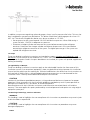
SPECIAL NOTES – Roof-Mounted Condenser
Pre-assemble the A/C hoses and
mounts to the condenser assembly
but do not crimp the bulk-head side
A/C fittings until the unit is installed.
Use reinforcement plates to prevent
damage to the roof skin.
Using the outline of the condenser
cover as a template, mark the
position of the two A/C bulkhead
fittings and the wiring harness pass-
through. The electrical harness pass-
through will be approximately
centered in front of the condenser.
Drill the holes as indicated below:
• #6 fitting - 5/8 in (16 mm)
• #8 fitting - 3/4 in (19 mm)
• Harness - 3/4 in (19mm)

8
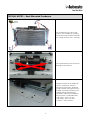
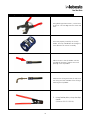
Burgaflex Crimp Procedure
1. Using blade-type hose cutters, cut the hose
in one cut. The cut edge must be clean and
flush.
2. Place two properly sized clips in the clip
holder. The clips should both be facing the
same direction for ease of assembly.
3. Slide the hose in the clip holder until the
cut edge of the hose is against the small
opening in the clip holder.
4. Lubricate the fitting with PAG oil and insert
the fitting until the shoulder of the fitting is
touching the clip holder.
5. Using Oetiker pliers, crimp the clips
closed.
(Webasto P/N 5012954A)

9
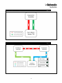
Refrigerant Hose Layout – Tie In
Fig. 1
VAC System Layout – Extreme
Fig. 2

10
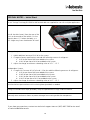
SPECIAL NOTES – Initial Start
In A/C fittings Tie-In bag 5013566 an M6 and M8 bolt are supplied for use with multiple applications.
Install the drain hose(s) from the rear of the
unit to the outside of the vehicle. Cut the
hose(s) about 1.5” below the body, at a
45º angle away from the direction of travel.
Charge the system:
1. Add 4 additional ounces of PAG oil to the system.
2. Charge to factory specifications and add the following amount of refrigerant:
a. 0.03 lbs per foot of #6 hose added to the system
b. 0.001 lbs per foot of #10 hose added to the system
3. Adjust the charge to achieve a subcooling value of 10º F - 15º F
Independent Systems
4. Charge with 5 ounces of PAG oil and 1.2 lbs plus add the following amounts of refrigerant:
a. 0.03 lbs per foot of #6 hose added to the system
b. 0.005 lbs per foot of #8 hose added to the system
c. 0.001 lbs per foot of #10 hose added to the system
d. 0.0015 lbs per foot of #12 hose added to the system
5. Adjust the charge to achieve a subcooling value of 10º F - 15º F
Insulate the low-pressure hose with insulating hose (provided) as needed.
Using anti-condensation tape (provided), wrap all exposed metal fittings inside the vehicle.
Securely route and mount hoses to prevent damage from moving and/or hot components.
If you have any questions, contact our technical support team at (800) 860-7866 or via email
at technical@webasto.com.

11
NOTES

12
In multilingual versions the English language is binding. The telephone number of the respective country is shown on the
Webasto service center leaflet or can be found on the website of your Webasto subsidiary.
Dans le cas d’une version rédigée en plusieurs langues, l’anglais est alors la langue qui fait foi. Pour trouver le numéro de
téléphone du pays concerné, veuillez consulter le dépliant des points-service Webasto ou la page web de la représentation
Webasto de votre pays.
Webasto Thermo & Comfort N.A., Inc.
15083 North Road
Fenton, MI 48430
Technical Assistance Hotline
USA: (800) 860-7866
Canada: (800) 667-8900
Org. 11/2019 Rev. 08/2023
im_5013390c_ac_hose_installation
www.webasto.us
www.techwebasto.com
-
 1
1
-
 2
2
-
 3
3
-
 4
4
-
 5
5
-
 6
6
-
 7
7
-
 8
8
-
 9
9
-
 10
10
-
 11
11
-
 12
12


Documents connexes
-
Webasto Universal Underbody Condenser Mounting Kit - Guide d'installation
-
-
-
-
-
-
-
-

