Vermont Casting 3980 Manuel utilisateur
- Catégorie
- Cheminées
- Taper
- Manuel utilisateur

INSTALLER / CONSUMER
SAFETY INFORMATION
20007067 1/07 Rev. 8
PLEASE READ THIS MANUAL
BEFORE INSTALLING AND USING
APPLIANCE.
WARNING!
IF THE INFORMATION IN THIS
MANUAL IS NOT FOLLOWED
EXACTLY, A FIRE OR EXPLOSION
MAY RESULT CAUSING
PROPERTY DAMAGE, PERSONAL
INJURY OR LOSS OF LIFE.
FOR YOUR SAFETY
Installation and service must be
performed by a qualified installer,
service agency or the gas suppler.
WHAT TO DO IF YOU SMELL
GAS:
• Do not try to light any appliance.
• Do not touch any electric switch; do
not use any phone in your building.
• Immediately call your gas supplier
from your neighbor’s phone. Follow
the gas supplier’s instructions.
• If you cannot reach your gas supplier,
call the fire department.
DO NOT STORE OR USE
GASOLINE OR OTHER
FLAMMABLE VAPORS AND
LIQUIDS IN THE VICINITY OF THIS
OR ANY OTHER APPLIANCE.
This appliance may be installed in an
after market permanently located
manufactured (mobile) home where not
prohibited by local codes.
This appliance is only for use with the
type of gas indicated on the rating plate.
This appliance is not convertible for use
with other gases unless a certified kit is
used.
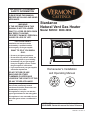
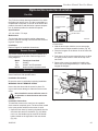
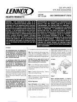
Stardance
Natural Vent Gas Heater
Model SNV30: 3980-3996
Homeowner’s Installation
and Operating Manual
CE R TI F IE D
7067
SDV fully assembled
cover
12/22/03
INSTALLER: Leave this manual with the appliance.
CONSUMER: Retain this manual for future reference.

22
Stardance Natural Vent Gas Heater
20007067
PLEASE READ THE INSTALLATION & OPERATING INSTRUCTIONS BEFORE USING APPLIANCE.
Thank you and congratulations on your purchase of a Vermont Castings stove.
IMPORTANT: Read all instructions and warnings carefully before starting installation. Failure to follow these
instructions may result in a possible fire hazard and will void the warranty.
Table of Contents
Installation & Operating Instructions .........................................................................................3
Stove Dimensions ...............................................................................................................4
Clearance Requirements .....................................................................................................5
Alcove Minimum Dimensions ..............................................................................................5
Hearth Requirements ..........................................................................................................5
Gas Specifications ...............................................................................................................6
Gas Inlet and Manifold Pressures .......................................................................................6
High Elevations ...................................................................................................................6
Venting Requirements .........................................................................................................6
Vent Layout and Height Requirements ................................................................................6
Passing Through a Combustible Wall or Ceiling .................................................................7
Venting Requirements .........................................................................................................7
Installation
Unpack the Stove ................................................................................................................8
Install the Optional Fan .......................................................................................................8
Venting System Assembly ...................................................................................................9
Paint Option for Enamelled Stoves ...................................................................................10
Connect the Gas Supply Line ............................................................................................10
Burner Information ............................................................................................................. 11
Install ON/OFF Switch ....................................................................................................... 11
Thermostat Connection ..................................................................................................... 11
Install the Logset ............................................................................................................... 11
Install the Front Plate ........................................................................................................12
Operation
Your First Fire ....................................................................................................................13
Pilot and Burner Inspection ...............................................................................................13
Flame & Temperature Adjustment .....................................................................................13
Flame Characteristics ........................................................................................................13
Lighting and Operating Instructions ...................................................................................14
Troubleshooting .................................................................................................................15
Fuel Conversion Instructions .............................................................................................16
Maintenance
Annual System Inspection .................................................................................................19
Logset and Burner Cleaning and Inspection .....................................................................19
Care of Cast Iron ...............................................................................................................19
Cleaning the Glass ............................................................................................................19
Glass Replacement ...........................................................................................................19
Gasket Replacement .........................................................................................................20
Inspect the Vent System Annually .....................................................................................20
Check the Gas Flame Regularly .......................................................................................20
Stove Disassembly ............................................................................................................20
Wiring Diagrams ................................................................................................................21
Replacement Parts .....................................................................................................................22
Optional Accessories ..................................................................................................................25
Warranty .......................................................................................................................................30
Energuide .....................................................................................................................................32

3
Stardance Natural Vent Gas Heater
20007067
The Stardance Natural Vent Room Heater, Model Nos. 3980-
3996 is a vented gas appliance listed to the ANSI standard
Z21.88b-2002 and CSA-2.33b-2002 for Vented Room Heaters,
and CSA 2.17-M91, Gas-Fired Appliances For Use at High Al
-
titudes.
The installation of the Stardance Natural Vent Room Heater
must conform with local codes, or in the absence of local codes,
with National Fuel Gas Code, ANSI Z223.1/NFPA 54 — latest edi-
tion and CSA B-149.1 Installation Code. (EXCEPTION: Do not
derate this appliance for altitude. Maintain the manifold pressure
at 3.5” w.c. for Natural Gas and 10” w.c. for LP gas at maximum
input.)
This appliance is only for use with the type of gas indicated on
the rating plate. This appliance is not convertible for use with other
gases unless a certified kit is used.
Installation and replacement of gas piping, gas utilization
equipment or accessories, and repair and servicing of equip-
ment shall be performed only by a qualified agency. The term
“qualified agency” means any individual, firm, corporation, or
company that either in person or through a representative is
engaged in and is responsible for (a) installation or replace-
ment of gas piping, or (b), the connection, installation, repair,
or servicing of equipment, who is experienced in such work,
familiar with all precautions required, and has complied with
all the requirements of the authority having jurisdiction.
The Stardance Natural Vent Room Heater should be
inspected before use and at least annually by a qualified
service agency. It is imperative that control compartments,
burners, and circulating air passageways of the appliance
be kept clean.
The Stardance Natural Vent Room Heater and its individual
shut-off valve must be disconnected from the gas supply piping
during any pressure testing of that system at test pressures in
excess of 1/2 psig (3.5 kPa).
The Stardance Natural Vent Room Heater must be isolated
from the gas supply piping system by closing its individual manual
shutoff valve during any pressure testing of the gas supply piping
system at test pressures equal to or less than 1/2 psig.
An accessible tap is located above the pilot/on-off knob for
checking the inlet pressure.
This appliance needs fresh air for safe operation and must be
installed so there are provisions for adequate combustion and
ventilation air.
This appliance must be properly connected to a listed 4”
(100mm) Type B venting system or to an approved masonry or
factory-built chimney system. In Canada, a complete reline of
Class A chimneys is required. This heater is equipped with a vent
safety shutoff system.
This appliance must be properly connected to a venting
system. WARNING: Operation of this heater when not con-
nected to a properly installed and maintained venting system
or tampering with the vent safety shutoff sytem can result in
carbon monoxide (CO) poisoning and possible death.
This appliance is approved for bedroom installations in the
U.S. and Canada.
This appliance may be installed in an aftermarket* manufactured
(mobile) home, where not prohibited by state or local codes.
The Stardance Natural Vent Room Heater, when installed,
must be electrically grounded in accordance with local codes or,
in the absence of local codes, with the National Electrical Code
ANSI/NFPA 70, (latest edition), or of the current Canadian Electri-
cal Code C22.1.
Due to high temperatures this appliance should be located
out of traffic and away from furniture and draperies.
WARNING: This appliance is hot while in operation. Keep
children, clothing, and furniture away. Contact may cause
burns or ignition of combustible materials.
Children and adults should be alerted to the hazards of high
surface temperatures and should stay away to avoid burns or
clothing ignition. Young children should be carefully super
-
vised when they are in the same room as the appliance.
Clothing or other flammable materials should not be placed
on or near the appliance.
Any safety screen, glass or guard removed for servicing
an appliance must be replaced prior to operating the appli-
ance.
The appliance area must be kept clear and free from com-
bustible materials, gasoline, and other flammable vapors
and liquids.
The flow of combustion and ventilation air must not be ob-
structed. The installation must include adequate accessibility
and clearance for servicing and proper operation.
WARNING: Do not operate the Room Heater with the glass
panel removed, cracked or broken. Replacement of the panel
should be done by a licensed or qualified service person.
Do not use this appliance if any part has been under water.
Immediately call a qualified service technician to inspect the
appliance and to replace any part of the control system and
any gas control which has been under water.
Do not burn wood, trash or any other material for which
this appliance was not designed. This appliance is designed
to burn either natural gas or propane only.
This gas appliance must not be connected to a chimney
flue serving a separate solid-fuel burning appliance.
CAUTION: Label all wires prior to disconnection when
servicing controls. Wiring errors can cause improper and
dangerous operation.
Verify proper operation after servicing.
* Aftermarket: Completion of sale, nor for purpose of resale,
from the manufacturer.
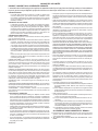
General Information
Proposition 65 Warning: Fuels used in gas, woodburning
or oil fired appliances, and the products of combustion of such
fuels, contain chemicals known to the State of California to
cause cancer, birth defects and other reproductive harm.
California Health & Safety Code Sec. 25249.6

44
Stardance Natural Vent Gas Heater
20007067
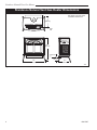
9"
(229mm)
C
L
Valve
Inlet
26"
(680 mm)
25"
(635 mm)
14"
(355 mm)
3"
(76 mm)
C
L
7067
Stardance fully assembled
dimensions
12/22/03 djt
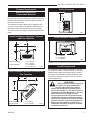
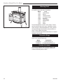
Valve Inlet
See Page 5 for Flue Collar
Centerline Dimensions.
4406
Fig. 1 Stardance dimensions.
Stardance Natural Vent Gas Heater Dimensions

5
Stardance Natural Vent Gas Heater
20007067
Clearance Requirements
Minimum Clearances to
Combustible Materials
Measure side clearances as shown in Figures 2
through 5 from the outer edge of the cast iron stove top.
Measure rear clearances from the outermost surface of
the sheet metal rear skirt.
The Stardance heater is approved for installation into
an alcove constructed of combustible materials to the
dimensions and clearances shown on the next page.
The same clearances apply in a standard parallel instal
-
lation.
Parallel Installation: Minimum Clearance
and Flue Centerline
Stove Clearances A: 5” (125mm)
B: 4” (102mm)
Pipe Centerlines C: 16” (406mm)
D: 9¹⁄₄” (235mm)
ST128b
Fig. 2 Parallel installation requirements.
C
L
C
L
ST128b
SNV flue centerline
5/11/00 djt
C
D
B
A
Corner Installation: Minimum Clearance and
Flue Centerline
ST129b
SNV
corner specs
5/25/01 djt
A
A
B
B
Stove Clearance A: 4” (102mm)
Pipe Centerline B: 17” (432mm)
ST129b
Fig. 3 Corner installation requirements.
Hearth Requirements
The Stardance Heater must be installed on rigid floor-
ing. When the heater is installed directly on any com-
bustible surface other than wood flooring, a metal or
wood panel extending the full width and depth of the
unit must be used as the hearth. There are no other
hearth requirements.
WARNING:
• Always maintain required clearances
(air spaces) to nearby combustibles
to prevent fire hazard. Do not fill air
spaces with insulation. All venting compo
-
nents must maintain a 1” (25 mm) clearance to
combustible materials. Maintain a 6” (152 mm)
c
learance when using single wall pipe.
• The gas appliance and vent system must be
vented directly to the outside of the building
and never be attached to a chimney serving a
separate solid fuel or gas-burning appliance.
• Refer to the manufacturer’s instructions in
-
cluded with the venting system for complete
installation procedures.
Ceiling Clearances
ST657
Fig. 4 Minimum ceiling clearance; minimu alcove height.
72"
(1829mm)
ST657
SNV
Min. Clg Clrnc
5/25/01 djt
45"
(1140mm)
Alcove Minimum Dimensions
ST658
SNV
alcove mins.
5/25/01 djt
B
A
A
C
A: 4” (102mm)
B: 33” (838mm)
C: 5” (125mm)
ST658
Fig. 5 The Stardance Natural Vent Stove is approved for
installation into alcoves built of combustible materials.

66
Stardance Natural Vent Gas Heater
20007067
Venting Requirements and Options
The Stardance must be properly connected to a listed
4” (102 mm) Type B venting system or to an approved
Class A masonry or factory-built chimney system. In
Canada, a complete relining of Class A chimney sys-
tems is required.
The Stardance Natural Vent stove will accept decora-
tive 6” (152 mm) stove pipe around the Type B venting
system, for aesthetic purposes.
Complete Type B vent systems are available from a
number of manufacturers, and your dealer can usually
supply one. Pipe sections from different makers are not
interchangeable; do not mix pipe or vent sections from
different makers. Follow the vent system manufactur-
er’s instructions.
The vent system should conform to the specifications of
the National Fuel Gas Code, latest edition.
If connecting to a Class A chimney system, use 4” (102
mm) single wall or 4” Type B vent connector. Single wall
vent connector requires a minimum 6” (152 mm) clear-
ance to combustible surfaces.
Exterior chimneys may be subject to flow reversal or
condensation. To lessen these conditions, enclose Type
B vents in an insulated chase, or reline exterior Class A
chimneys.
An approved pass-through device is always required,
whether the vent system passes through a wall or
a ceiling. Use a pass-through device from the same
maker who supplies the venting system.
Venting terminals shall not be recessed into a wall or
siding.
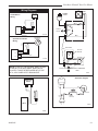
Vent Layout and Height Requirements
Venting for a Stardance can rise vertically through the
home, or can pass through an exterior wall and rise
along the outside of the home. Some codes require that
a Type B vent system rising on the outside of the home
be enclosed in a chase. Check your local codes for
requirements.
The minimum vent system height for the Stardance
Natural Vent Stove is 8’ (2.43 m), (Fig. 7) measured
from the top of the stove. To determine the minimum
height the vent system must extend through or past the
roof, refer to the 1993 edition of the National Fuel Gas
Code.
Weight: Fully assembled 350 lbs.
Inlet Minimum 5.5” w.c. 11” w.c.
Inlet Maximum 14” w.c. 14” w.c.
Manifold Pressure 3.5” w.c. 10” w.c.
Gas Inlet and Manifold Pressures
Natural LP (Propane)
Stardance Natural Vent
Certified to:
ANSI Z21.88-2005 / CSA Z2.33-2005
Vented Gas Fireplace Heaters
The installation must conform with local codes or, in
the absence of local codes, with the National Fuel Gas
Code, ANSI Z223.1/NFPA 54 - latest edition. (EXCEP-
TION: Do not derate this appliance for altitude. Main-
tain the manifold pressure at 3.5” w.c. for Natural Gas
and 10” w.c. for Propane.)
High Elevations
Input ratings are shown in BTU per hour and are
certified without deration for elevations up to
4,500 feet (1,370m) above sea level.
For elevations above 4,500 feet (1,370m) in USA,
installations must be in accordance with the
current ANSI Z223.1/NFPA 54 and/or local codes
having jurisdiction.
In Canada, please consult provincial and/or local
authorities having jurisdiction for installations at
elevations above 4,500 feet (1,370m).
WARNING: Improper installation, adjust-
ment, alteration, service or maintenance
can cause injury or property damage. Refer
to this manual for correct installation and
operational procedures. For assistance or
additional information consult a qualified
installer, service agency, or the gas supplier.
Gas Specifications
Max. Min.
Input Input
Model Fuel Gas Control BTU/h BTU/h
SNV30RN Nat Millivolt 28,000 19,000
SNV30RP Prop Millivolt 28,000 21,500

7
Stardance Natural Vent Gas Heater
20007067
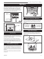
Passing Through a
Combustible Wall or Ceiling
An approved pass-through device is always required
when a vent passes through a combustible wall or ceil-
ing. Check with the maker of the vent system for the
correct listed devices that are available. A listed pass-
through device is required whether or not the installa-
tion includes decorative pipe around the Type B venting
system. NOTE: It is essential to seal between the ceil-
ing support (sometimes called a ‘firestop spacer’) and
the decorative pipe, if installed, with a high-temperature
silicone sealant. (Fig. 6)
Complete the venting system installation according to
the manufacturer’s instructions.
ST361
Ceiling pass thru
5/11/00 djt
Joists
Ceiling
Support
Trim Col
-
lar
Air Space
Listed 4”
(102 mm)
B-Vent
Decorative
6” Pipe
High-tempera-
ture Silicone
Sealant
Air Space as Re-
quired by Code
ST361
Fig. 6 A ceiling pass-through, with decorative pipe around the
vent.
High-tem-
perature
Silicone
Sealant
Fig. 7 Vent termination window.
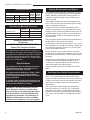
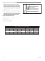
Venting Requirements
FP567
NVBR/NVBC VENTING RUNS
11/12/97
Venting Runs
A: Vertical installations up to 36 feet (12m) in
height. Up to an 18 ft. horizontal vent run can be
installed within the vent system using a
maximum of two 90-degree elbows or four
45-degree elbows.
B: Vertical installations up to 36 feet (12m) in
height. Up to a 24 ft. horizontal vent run can be
installed within the vent system using a
maximum of two 45-degree elbows.
(Ratio = 2/3, Hor./Vert.)
= Acceptable venting configuration
= Unacceptable venting configuration
NOTE: When venting staight vertical, without an
elbow, a minimum of 8 ft. vertical is required
off the top of the stove.
Horizontal Run (in feet)
Vertical Run (in feet)
(Measured from top of the unit before any elbow)
36
34
32
30
28
26
24
22
20
18
16
14
12
10
8
6
4
2
1 2 4 6 8 10 12 14 16 18 20 22 24
A
B
FP567b

88
Stardance Natural Vent Gas Heater
20007067
ST640
RUVSOD
snapstat
7/01
Snapstat Bracket
Snapstat Module
Pinch
Grommet to
Remove
ST670
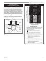
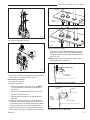
Fig. 9 Remove the snapstat and grommet from the bracket
4. Connect snapstat leads. Disconnect the snapstat
module from the leads inside the snapstat bracket.
(Fig. 9) Bend open the snapstat bracket. Use needle
nose pliers to remove the black plastic grommet
from the bracket. Discard the bracket. Connect
the two wires to the two snapstat extension leads
located between the inner and outer shroud.
5. Position the fan assembly so the ducts slide be
-
tween the inner and outer shroud. The inner shroud
should engage with the two slots in the ends of the
bracket so the bracket and shroud are interlocked.
(Fig. 10) Secure the bracket with the four sheet
metal screws provided in the finish bag.
6. Install the snapstat by loosening the front screw on
the inner side of the duct. (Fig. 11) Slide the snapstat
under the head of the screw and tighten. Connect
the leads to the snapstat. Make sure the snapstat
assembly is mounted straight front to back.
7. Reattach rear shroud assembly in reverse order of
Step 2. Tighten bottom bolts to hold shroud in place.
WARNING
This appliance is equipped with a three-prong
(grounded) plug for your protection against shock
hazard and should be plugged directly into a
properly grounded three-prong receptacle. Do not
cut or remove the grounding prong from this plug.
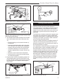
Install the Optional Fan
If you are installing the optional convection Fan Kit
#2767 (FK26), continue here. If you are not installing a
fan kit, proceed to Venting System Assembly.
1. The fan kit includes a blower assembly and a rheo
-
stat assembly, connected by a cable. The blower as-
sembly mounts to the bottom rear of the stove, and
the rheostat mounts to the left side of the valve. The
assembly includes a ‘snapstat’ which automatically
turns the fan ON (or OFF) above (or below) approxi-
mately 109°F. The rheostat also provides a range
of fan speed settings from Off (which overrides the
snapstat function) to High. Unpack and inspect the
blower assembly. Confirm that the fan spins freely.
2. Remove the rear shroud by loosening the two (2)
bolts at the bottom left and right side of the shroud.
Slide shroud straight up, rotate the bottom out and
away from stove and pull shroud out.
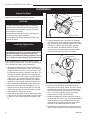
3. Attach the fan assembly to the fan bracket provided
in the log box. Use #10 sheet metal screws provided
in fan kit. Do not remove finger guard screws. (Fig.
8)
Installation
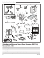
Unpack the Stove
The Stardance is shipped fully assembled on its back.
Unpack the stove and carefully set it upright.
ST669
RUVSOD
attach fan to bracket
7/01
Snapstat
Wire
Rheostat Wire
Fan Bracket
Finger Guard
ST669
Fig. 8 Attach the fan assembly to the fan bracket.
CAUTION
Porcelain enamelled surfaces are fragile. Handle
porcelain enamelled castings tenderly. Familiarize
yourself with the assembly steps before you begin
and proceed with deliberation and care. If possible,
have assistance available.
Place enamelled castings on a soft, cushioned sur-
face until you are ready to assemble.
Avoid contact between the castings and other hard
surfaces or objects.

9
Stardance Natural Vent Gas Heater
20007067
ST194
attach fan to shroud
11/99
Outer
Shroud
Slot
Inner Shroud
Slot
ST194
Fig. 10 Position the fan to engage the inner shroud with the
fan bracket slots and secure with sheet metal screws.
ST347a
JUV
FK28
rheostat install
9/21/00
Retaining Nut
Control Knob
ST347a
Fig. 12 Attach rheostat to left side of valve.
MOTOR
SNAPSTAT
ON/OFF
RHEOSTAT
WHT
WHT
BLK
BLK
BLK
GRN
BLK
POWER
ST196
FK26 fan diangram
11/99
ST196
Fig. 13 #2767 / FK26 fan wiring diagram.
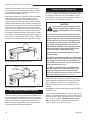
Venting System Assembly
Adjust the leg levelers as needed. They should not
extend any further from the leg than necessary.
The venting collar is on the sheet metal draft hood/heat
exchanger assembly, over the firebox. Use a B-vent
adapter, from the same maker as the rest of the B-vent
components, to join the first section of venting to the
draft hood.
The SNV30 stove includes a spill switch. Operating this
stove when not connected to a properly installed and
maintained venting system, or tampering with or discon-
necting the spill switch, can result in carbon monoxide
(CO) poisoning and possible death.
The stove includes a bracket for installing decorative 6”
(152mm) round stove pipe around the B-vent, for ap-
pearance purposes only. The decorative pipe need not
be concentric with the vent pipe.
If the installation includes decorative stove pipe around
the venting system, make a cardboard template of the
decorative pipe by tracing its circumference. Put this
template in the flue recess in the stove top. Position the
template to fit well against the front of the recess. (Fig.
14) Use this template to locate the bracket to hold the
decorative pipe. Depending on spacing, the bracket
may fit inside the decorative pipe without interfering
with the vent system. Fasten the bracket to the draft
hood/heat exchanger assembly with a sheet metal
screw.
ST372
attach
decorator pipe
bracket
5/19/00 djt
Template
Sheet Metal Screw
Bracket
ST372
Fig. 14 Use a template to locate the bracket for decorative
pipe to surround the B-vent pipe.
ST671
attach snapstat
Snapstat
Left Air Duct
ST671
Fig. 11 Install the snapstat and connect the extension wire
terminals. View is with top removed, however, access is avail-
able through the grille opening.
NOTE: Shown without
top for clarity.
8. The rheostat control switch attaches to the left side
of the valve bracket at the front of the stove. (Fig.
12)
• Remove retaining nut from shaft of rheostat. (if
preinstalled)
• Insert the rheostat through the hole in the back
of the left side of the valve bracket, aligning the
locator pin with the smaller hole in that bracket.
• Thread the retaining nut onto the shaft of the
rheostat, tightening with a wrench. Do not over-
tighten.
• Attach the control knob to the rheostat shaft.
• Use the wire tie to secure the fan and rheostat
wire harnesses together.
9. Plug the power cord into a standard grounded 110
volt household outlet. If the fan control knob is not
turned to the OFF position, the fan will turn on when
the temperature at the snapstat reaches approxi-
mately 109°F.

1010
Stardance Natural Vent Gas Heater
20007067
Insert the B-vent adapter into the flue collar and drill
1/8” (3mm) pilot holes through both the stove’s collar
and the adapter. Attach the adapter to the flue collar
with sheet metal screws. (Fig. 15)
Attach the first section of venting to the B-vent adapter.
Depending on the length of the individual venting
sections and the lengths of the decorative pipe, you
may need to slip the decorative pipe over the venting
sections before attaching upper sections to lower ones.
The sections of decorative pipe should be oriented with
their seams (if any) toward the wall; sections usually
do not need to be fastened at each joint, other than slip
sections. The decorative pipe need not be fastened to
the locating bracket on the stove. If the layout includes
a slip section, this should be the last section of pipe vis-
ible in the room at the ceiling. Refer to Page 7, Figure 6
for details on joining the decorative pipe at the ceiling.
ST373
attach
b vent adapter
5/19/00 djt
ST373
Fig. 15 Attach the B-vent adapter to the flue.
ST374
attach
decorative pipe
5/19/00 djt
B-vent Pipe
Decorative
Pipe 7FSSK
Bracket
ST374
Fig. 16 Install decorative pipe over the B-vent pipe.
Paint Option for Enamelled Stoves
If you wish to match the decorative or vent pipe to the
color of the stove, paint the pipe before installation. Use
only a high-temperature paint. Paint only in a well-venti-
lated area. Mask the surroundings to prevent overspray.
Apply the paint lightly; two light coats will result in a
better finish than a single heavy coat. Let the paint dry
thoroughly before handling painted parts.
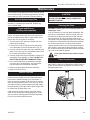
Connect the Gas Supply Line
Check the Rating Plate attached by a steel cable to the
firebox, to confirm that you have the appropriate firebox
for the type of fuel to be used. The Stardance may be
converted from one gas to another using the appropri-
ate Fuel Conversion Kit listed on Page 24.
This appliance should only be connect-
ed by a qualified gas technician. Test to
confirm manifold pressures as specified
below.
The Stardance Heater and its individual shutoff
valve must be disconnected from the gas supply
piping during any pressure testing of that system
at test pressures in excess of 1/2 psig (3.5 kPa).
The Stardance Heater must be isolated from the
gas supply piping system by closing its indi-
vidual manual shutoff valve during any pressure
testing of the gas supply piping system at test
pressure equal to or less than 1/2 psig.
There must be a gas shutoff between the stove
and the supply.
In order to connect Natural Gas, use a fitting with
3/8” NPT nipple on the valve side and 1/2” natural
gas supply line with an input of 28,000 BTUs at
a manifold pressure of 3.5” and a minimum inlet
supply pressure of 5.5” w.c.
In order to connect Propane, use a fitting with
3/8” NPT nipple on the valve side and 1/2” pro-
pane gas supply line with an input of 26,000
BTUs at a manifold pressure of 10.0” and a mini-
mum inlet supply pressure of 11.0” w.c.
In the U.S.; Gas connection should be made in ac-
cordance with current National Fuel Gas Code, ANSI
Z223.1/NFPA 54. Since some municipalities have
additional local codes, be sure to consult you local
authority.
In Canada; consult the local authority and CSA-B149.1
installation code.
Connect the gas supply and test for leaks. Use a 50/50
solution of liquid soap and water to test for leaks at gas
fittings and joints. Apply water/soap solution with brush
only - do not over apply. NEVER test with an open
flame. Light the pilot according to the directions on
Page 14, before going to the next step.
CAUTION

11
Stardance Natural Vent Gas Heater
20007067
Burner Information
The appliance must only use the gas specified on the
rating plate, unless converted using a Fuel Conversion
Kit. Refer to Page 25 for the correct Fuel Conversion Kit
for your model.
Conversion instructions are provided with each kit and
beginning on Page 16 in this manual.
In order to connect Natural Gas, use a fitting with
3/8” NPT nipple on the valve side and 1/2” natural gas
supply line with an input of 28,000 BTUs at a manifold
pressure of 3.5” and a minimum inlet supply pressure of
5.5” w.c.
In order to connect Propane, use a fitting with 3/8”
NPT nipple on the valve side and 1/2” propane gas
supply line with an input of 26,000 BTUs at a manifold
pressure of 10.0” and a minimum inlet supply pressure
of 11.0” w.c.
Install ON/OFF Switch
The switch assembly parts are found in the parts bag.
1. Attach switch assembly to left rear side of stove
shroud (when facing shroud) using two screws and
existing holes in shroud. (Fig. 17)
2. Run wires down back of stove, under bottom of rear
shroud to valve.
3. Attach wires to valve terminals. (Fig. 18)
ST315
attach switch assy
1/31/00 djt
Switch As-
sembly
Screws
Existing
Holes
ST315
Fig. 17 Attach switch assembly to rear shroud.
THIS APPLIANCE SHOULD BE CON-
NECTED TO THE GAS SUPPLY ONLY BY
A QUALIFIED GAS SERVICE TECHNICIAN.
FOLLOW ALL LOCAL CODES.
THERE MUST BE A GAS SHUT-OFF BE
-
TWEEN THE STOVE AND THE SUPPLY.
PILOT
ADJ
TP
TH
TPTH
ST228
attach switch
wires to valve
12/99
ST228
Fig. 18 Attach switch wires to valve.
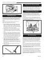
Install the Log Set
NOTE: The bracket shipped with logs is for fan installa-
tion only.
1. Remove the logs from their packaging, and inspect
each piece for damage. DO NOT INSTALL DAM-
AGED LOGS.
2. Install the rear log centering it side to side on the
sheet metal shelf at the back of the firebox. (Fig. 19)
The log will touch both sides and the back wall of the
firebox.
3. Install the right log by engaging hole on bottom with
pin on the rear log. (Fig. 19) Then set right bottom
side on the burner so the edge of the log touches
the right side of the firebox. The right log does not
use the locator pins on the burner to stay in place.
4. Install the left log by engaging hole on bottom with
pin on rear log. (Fig. 21) Then set left bottom side
on the burner so the edge of the log touches the left
side of the firebox.
5. Loosely sprinkle the lava rocks directly on top of the
burner in front of and between the decorative grate
and the right and left logs. Use the lava rock to cover
brackets on the burner. (Fig. 20)
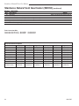
Thermostat
Wire / Gauge Maximum Run
18 40 feet
20 25 feet
22 16 feet
Thermostat Connection (optional)
Use only a thermostat rated for 500 - 750 millivolts.
Check the table below for the appropriate gauge
thermostat wire to use for the length of lead required in
your installation.
1. Install the wall thermostat in the desired location and
run the wires to the stove location. Terminate these
leads with 1/4” female connectors.
2. Connect the thermostat wires to the valve. (Fig. 18)

1212
Stardance Natural Vent Gas Heater
20007067
Install the Front Plate
Hold the front plate by the window bars and lift it into
position, engaging the two steel tabs on the top corners
behind the adjacent bosses in the side plates. (Fig. 21)
Then seat the Front against the sides so the tabs at the
bottom lip engage with the notches in the stove legs.
When properly installed, the bottom of the Front Plate
cannot be pulled away from the sides without also lifting
it.
This completes assembly of the Stardance stove.
LG142
Fig. 20 Completed log installation.
LG142
Stardance
Install logs 2
12/11/00 djt
Lava Rock
Fig. 19 Install the back, left and right logs.
LG141
Right
Log
LG141
Stardance
Install logs 1
12/11/00 djt
Decorative Grate
Rear Log
Left Log
ST783
SNV
Install front
11/20/03
Engage steel tabs
behind the cast
iron bosses
Bottom tabs engage
notch in the leg
ST783a
Fig. 21 Install the front plate.

13
Stardance Natural Vent Gas Heater
20007067
Fig. 22 To open the front doors, turn handle clockwise.
ST261
Stardance
operable doors
1/31/01
Clockwise
to Open
Counterclockwise
to Close
ST624
The Stardance is operated with the operable door front
plate in place with the doors open or closed. To open
the front doors, insert the handle into the door latch
stub and turn it to the left and up. (Fig. 22) When not in
use, the handle may be stored in the handle holder on
the right side of the rear shroud. (Fig. 23)
Operation
Your First Fire
Read these instructions carefully and familiarize
yourself with the burner controls shown in Figure 27.
Locate the pilot assembly, Figure 24. Follow the lighting
instructions on Page 14 exactly.
During the first fire, it is not unusual to smell some
odor associated with new logs, paint and metal being
heated. Odors should dissipate within an hour or so,
however, you can open a window to provide fresh air to
alleviate the condition.
Pilot and Burner Inspection
Each time you light your heater check that the pilot
flame and burner flame patterns are as shown in Figure
26. If flame patterns are incorrect, turn the heater off.
Contact your dealer or a qualified gas technician for as-
sistance. Do not operate the heater until the pilot flame
is correct.
Follow regular maintenance procedures as described
on Page 19.
ST624
handle holder
2/6/01
Handle
Holder
ST624
Fig. 23 When not in use, store handle in the handle holder.
ST477
Stardance
pilot location
10/4/00
Fig. 24 Pilot Assembly location.
ST476
Pilot As-
sembly
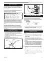
Flame & Temperature Adjustment
For stoves equipped with HI/LO valves, flame adjust-
ment is accomplished by rotating the HI/LO adjustment
knob located near the center of the gas control valve.
(Fig. 25)
Flame Characteristics
It is important to periodically perform a visual check
of the pilot and the burner flames. Compare them to
Figure 26. If any of the flames appear abnormal, call a
service person.
Turn
counterclockwise
to decrease
flame height
Turn clockwise
to increase
flame height
HV102
Honeywell hi/lo knob
4/5/99 djt
Fig. 25 Flame adjustment knob for Honeywell valve.
CO105c
Pilot flame
4/10/00 djt
LG143
Fig. 26 Correct pilot and burner flame pattern.
LG142
Stardance
Install logs 2
12/11/00 djt
Red Glow
CO105c

1414
Stardance Natural Vent Gas Heater
20007067
3. Open control access panel.
4. Push in gas control knob slightly and turn clock-
wise to “OFF”. Do not force.
5. Close control access panel.
1. STOP! Read the safety information above.
2. Turn off all electrical power to the fireplace.
3. For MN/MP/TN/TP appliances ONLY, go on to
Step 4. For RN/RP appliances turn the On/Off
switch to “OFF” position or set thermostat to
lowest level.
4. Open control access panel.
5. Push in gas control knob slightly and turn
clockwise to “OFF”.
10. Push the control knob all the way in and hold.
Immediately light the pilot by repeatedly depress-
ing the piezo spark ignitor until a flame appears.
Continue to hold the control knob in for about one
(1) minute after the pilot is lit. Release knob and it
will pop back up. Pilot should remain lit. If it goes
out, repeat steps 5 through 8.
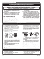
FOR YOUR SAFETY READ BEFORE LIGHTING
• If you cannot reach your gas supplier, call the
Fire Department
C. Use only your hand to push in or turn the gas
control knob. Never use tools. If the knob will not
push in or turn by hand, do not try to repair it, call a
qualified service technician. Applying force or any
attempted repair may result in a fire or explosion.
D. Do not use this fireplace if any part has been under
water. Immediately call a qualified service techni
-
cian to inspect the heater and to replace any part of
the control system and any gas control which has
been under water.
A. This heater has a pilot which must be lit manu-
ally. When lighting the pilot follow these instruc-
tions exactly.
B. BEFORE LIGHTING smell all around the heater
area for gas. Be sure to smell next to the floor
because some gas is heavier than air and will
settle on the floor.
WHAT TO DO IF YOU SMELL GAS
• Do not try to light any fireplace
• Do not touch any electric switch
• Do not use any phone in your building
• Immediately call your gas supplier from a
neighbor’s phone. Follow the gas supplier’s
instructions.
To Turn Off Gas To Heater
Lighting and Operating Instructions
1. Turn the On/Off switch to Off position or set the
thermostat to lowest setting.
2. Turn off all electric power to the fireplace if
service is to be performed.
Lighting Instructions
6. Wait five (5) minutes to clear out any gas. Then
smell for gas, including near the floor. If you
smell gas, STOP! Follow “B” in the safety infor-
mation above. If you do not smell gas, go to the
next step.
7. Remove glass door before lighting pilot. (See
Glass Frame Removal section).
8. Visibly locate pilot by the main burner.
9. Turn knob on gas control counterclockwise
to “PILOT”.
• If knob does not pop up when released, stop
and immediately call your service technician or
gas supplier.
• If after several tries, the pilot will not stay lit,
turn the gas control knob to “OFF” and call your
service technician or gas supplier.
11. Replace glass door.
12. Turn gas control knob to “ON” position.
13. For RN/RP appliances turn the On/Off switch to
“ON” position or set thermostat to desired setting.
14. Turn on all electrical power to the fireplace.
WARNING:If you do not follow these instructions exactly, a fire or explosion
may result causing property damage, personal injury or loss of life.
Euro SIT SIT NOVA
Honeywell
PILOT
ON
OFF
ON
P
I
L
O
T
O
F
F
O
F
F
FP1067
lighting instruction
knobs
3/9/01 djt
5
4
3
2
1
O
F
F
P
i
l
o
t
3/8" - 1/2"
FP1068
Lighting instructions
Pilots

15
Stardance Natural Vent Gas Heater
20007067
A. Defective or misaligned Using a match, light [ilot. If pilot lights, turn off pilot and
electrode at the pilot push the ignitor button again. If pilot will not light, check
gap at electrode and pilot - it should be 1/8” to have a
strong spark.
B. Defective ignitor (push Push piezo ignitor button. Check for spark at electrode
button) and pilot. If there is no spark at the pilot, and electrode
wire is properly connected, replace ignitor.
A. Defective pilot generator Check pilot flame. It must impinge on the thermocouple
(thermocouple) or thermopile. NOTE: This pilot burner assembly uses
both a thermocouple adn a thermopile. The thermo-
couple operates the pilot flame. Tighten the thermo-
couple. The thermopile operates the main valve. (ON
and OFF) Clean and/or adjust pilot for maximum flame
impingement on thermocouple and thermopile.
B. Defective automatic valve Turn valve knob to “Pilot”. Maintain flow to pilot; millivolt
operator mete should read greater than 10mV. If the reading is
okay and the pilot does not stay on, replace the gas
valve. NOTE: An interrupter block (not supplied) must
be used to conduct this test.
C.Defective safety switch Check the continuity accross the safety limit switch with
the unit cold. If there is no continuity, the safety switch
needs to be replaced.
A. Remote switch or wires Check rocker switch and wires for proper connection
defective Use jumper wires across terminals at rocker switch. If
burner lights, replace rocker switch. If okay, use jumper
wires across rocker switch wires at the valve. If burner
lights, wires are faulty or connections are bad.
B. Thermopile may not gen- 1. Be sure wire connecitons from thermopile at gas
ate sufficient voltage valve terminals are tight and thermopile is fully inserted
into pilot bracket.
2. One of the rocker switch wires may be grounded
Remove rocker switch wire form valve termianls. If
burner now stays lit, trace rocker switch wiring from
ground. It may be grounded to the appliance of the
gas supply line.
3. Check the thermopile with a millivolt meter. Take
reading at thermopile (“TP” and “TP/TH”) terminals of
gas valve. Should read 325 millivolts minimum while
holding valve knob depressed in PILOT position and
with rocker switch OFF. Replace faulty thermopile if
reading is below specified minimum.
C. Plugged burner orifice Check burner orifices for debris, and remove.
D. Defective automatic valve Turn knob to ON, place rocker switch to ON. Millivolt
operator meter should read greater than 10mV. If the reading is
okay and the burner does not light, replace the valve.
A. Pilot flame may be too low Clean and/or adjust pilot flame for maximum flame
or high, (blowing or lifting). impingement on thermocouple and thermopile.
causing the pilot to drop out
B. Possible blockage of the Check the vent termianl for blockage.
vent terminal
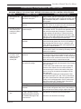
Troubleshooting / Honeywell #8420 Gas Control System
NOTE: Before troubleshooting the gas control system, be sure the external gas shutoff is in the “ON” position.
WARNING: REMOVE THE GLASS PANEL BEFORE PERFORMING ANY GAS CONTROL SERVICE WORK.
SYMPTOM
POSSIBLE CAUSES
CORRECTIVE ACTION
1. Spark ignitor will
not light
2. Pilot will not stay lit
after carefully fol-
lowing the lighting
instructions
3. Pilot lights, no gas
to burner, valve
knob ON, remote
switch (rocker
switch) ON
4. Frequent pilot out-
age

1616
Stardance Natural Vent Gas Heater
20007067
Conversion Precautions
Conversion must be completed only by qualified
personnel. Before proceeding, turn control knob on
valve to OFF and turn gas supply OFF. Turn OFF any
electricity that may be going to the appliance. CAU-
TION: Allow stove to cool completely before beginning
conversion.
Conversion Procedure
1. Remove stove front. Lift stove front up and then
swing bottom out and away to disengage from the
stove body. (Page 19, Fig. 35)
2. Swing open the swiveling latches at the top left and
right corners of the glass frame. (Page 20, Fig. 36)
3. Pull the top edge of the glass and frame assembly
away from the firebox face. Place the assembly out
of the way on a flat, padded surface such as a coun
-
ter protected by a towel.
4. Remove the logset from the firebox.
5. Remove the rear log bracket by loosening the screw
and sliding the bracket up. CAUTION: Do not re-
move the screw completely. It would be very difficult
to replace. (Fig. 28)
CO100
Gas conversion
HI-LO knob
3/15/99 djt
L
O
H
I
L
O
H
I
Cap
Hi-Lo
Knob
Lift Open
Center Screw
CO100
Fig. 29 Remove center screw from Hi-Lo knob.
Fuel Conversion Instructions
WARNING! This conversion kit shall be installed
by a qualified service agency in accordance with
the manufacturer’s instructions and all applicable
codes and requirements of the authority having
jurisdiction. If the information in these instruc-
tions is not followed exactly, a fire, explosion
or production of carbon monoxide may result
causing property damage, personal injury or loss
of life. The qualified service agency is respon-
sible for the proper installation of this kit. The
installation is not proper and complete until the
operation of the converted appliance is checked
as specified in the manufacturer’s instructions
supplied with the kit.
CAUTION: The gas supply shall be shut off prior
to disconnecting the electrical power, before pro-
ceeding with the conversion.
ST350
Jefferson
air shutter adj
3/20/00 djt
Remove
Screws
Rear Log Bracket
Pilot
Left & Right Log
Bracket Assembly
ST350
Fig. 28 Remove rear log bracket and left and right log
bracket assembly.
Loosen Screw
ST226
attach gas line
12/8/99 djt
PILO
T
O
N
O
F
F
PILO
T
AD
J
L
O
H
I
Main
Gas Line
Gas Supply Inlet
ST226
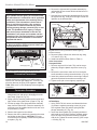
Fig. 27 Attach the gas line to the left side of the valve.
6. Remove the right and left log bracket assembly by
unfastening the two screws which hold the burner in
place. (Fig. 28)
7. Hold the burner at the right hand side and lift to clear
the right burner leg. Then pull to the right to clear the
injectors on the left hand side.
8. Remove injector orifices from left burner leg using
1/2” wrench. (Fig. 34)
9. Install conversion orifices. (Refer to Table 2)
Valve Conversion
Honeywell Valve
1. Remove cap from Hi-Lo knob. This can be accom
-
plished by lifting the plastic cap off the screw. (Fig.
29)
2. Remove the screw from center of Hi-Lo knob with
small screwdriver turning counterclockwise. (Fig. 29)
3. Insert blue painted screw when converting to natural
gas and red painted screw when converting to LP.
4. Tighten screw (do not over tighten), replace cap.
SIT 820 Valve
1. Using TORX T20 bit, remove and discard the three
(3) pressure regulator mounting screws (A), pres-
sure regulator tower (B) and the spring and dia-
phragm assembly (C). (Fig. 30)
2. Insure the rubber gasket (D) is properly positioned
and install the new HI/LO pressure regulator assem-
bly to the valve using the new screws (E) supplied
with the kit. Tighten the screws securely. (Ref. torque
= 25 in/lb) (Fig. 31)

17
Stardance Natural Vent Gas Heater
20007067
FC107
SIT820
valve conversion
10/03
A
B
C
O
F
F
P
I
L
O
T
O
Fig. 30 Remove mounting screws, pressure regulator tower
and spring and diaphragm assembly.
FC107
D
E
F
FC108
SIT
regulator
conversion
10/03
O
F
F
P
I
L
O
T
O
FC108
Fig. 31 Replace regulator.
3. Install the enclosed conversion label (F) to the valve
body where it can easily be seen. (Fig. 31)
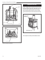
Pilot Orifice Conversion
14. Locate pilot. (Fig. 28)
15. Replace pilot orifice.
• Remove pilot hood by lifting up. (Fig. 32) NOTE:
It is not necessary to remove the pilot tube for
conversion.
• Remove pilot orifice with allen wrench. (Fig. 33)
• Install the conversion orifice.
• Reinstall pilot hood. Be sure to align hood with
index tab.
16. Adjust air shutter on the burner. The air shutter is
located on the bottom of the burner on the left. (Fig.
34) Loosen the two nuts holding the shutter in place.
On natural gas units, the shutter is shipped fully
closed. To convert to LP, reset the shutter as speci-
fied in Table 2. (Fig. 35) On propane unit the shutter
CO105a
gas conversion
Pilot
1/28/00 djt
Pilot Hood
Pilot
Bracket
CO105a
Fig. 32 Remove pilot hood.
CO106a
DV360/580
Gas Conversion
Pilot2
1/28/00 djt
Index Tab
Snap Ring
Allen Wrench
CO106a
Fig. 33 Remove pilot orifice.
is set at 1/8” or 3/8” opening depending on rating
plate serial number. To convert to natural gas, the
shutter should set to fully closed. Refasten the two
nuts. (Fig. 35)
NOTE: Be sure burner leg remains at a 90° angle to
firebox base after conversion.
ST785
SNV
air shutter
lp gas position
11/20/03 djt
3/8"
Air Shutter
(LP Position)
ST785
Fig. 34 LP air shutter settings.
ST718
SNV
air shutter
natural gas position
8/23/02 djt
Burner
Air Shutter
ST784
Fig. 35 Natural gas air shutter setting.
Rear
Injector
Air Inlet
Covered
Front Injector
Air Inlet

1818
Stardance Natural Vent Gas Heater
20007067
17. Replace burner. Slide the burner in at an angle
with left side lower than the right side. Slide the left
side onto the injectors, making sure the burner leg
remains at a 90° angle to the base. Lower the right
hand side down in to place. Make sure the burner is
as far left as possible and the injector shoulders are
inside the burner.
NOTE: It is very critical to keep the left burner leg,
which holds the injectors, at a 90° angel to the base.
(Fig. 36) This keeps the orifices aligned with the
tubes inside burner. Failure to do so could affect the
flame appearance and performance of the unit.
18. Place conversion label on valve.
19. Reinstall the right and left log bracket assembly.
20. Replace logs.
21. Replace glass and stove front.
22. Check manifold pressure.
23. Conversion is complete.
Fig. 36 Remove and replace injector orifices.
ST353a
injector orifice
replace
3/21/00 djt
90°
Left Burner Leg
Injector Orifices
ST353a
Conversion to LP Input (BTU/h) Air Shutter
Kit # Front Part # Rear Part # Minimum Maximum Setting
000-5022 #69 / .029” 30000513 #54 / .055” 20000130 21,500 28,000 3/8” Open
Conversion to Natural Gas Input (BTU/h) Air Shutter
Kit # Front Part # Rear Part # Minimum Maximum Setting
000-5021 #54 / .055” 20000130 #44 / .086” 30000334 19,000 28,000 Fully Closed
Table 2. Injector Orifice Size Matrix

19
Stardance Natural Vent Gas Heater
20007067
Maintenance
Your Stardance Gas Heater will provide years of service
with minimal upkeep. The following procedures will help
ensure that your stove continues to function properly.
Annual System Inspection
Have the entire heater and venting system inspected
annually by a qualified gas technician. Replace any
worn or broken parts.
Logset and Burner /
Cleaning and Inspection
Cleanliness is critical to the proper function of the
heater. The logset and burner must all be kept free of
dust and unobstructed by debris. Inspect these areas
before each use and clean as necessary.
1. Turn the burner OFF and let the heater cool com
-
pletely before cleaning.
2. Lift the Stove Front up and then swing the bottom
out to disengage it from the heater shell. (Fig. 37)
3. Carefully remove the glass and frame assembly and
place it out of the way on a flat, padded surface such
as a counter protected by a towel.
4. Carefully inspect the Logs for damage. Contact your
local dealer if any damage is evident. DO NOT OP-
ERATE THE HEATER WITH DAMAGED LOGS.
5. Use a soft bristled brush to sweep dust or debris
from the Logs, Pilot and Burner. Use care as the
logs are fragile and susceptible to damage.
6. Replace the glass panel and frame assembly.
7. Replace the Stove Front.
Care of Cast Iron
An occasional dusting with a dry rag will help keep the
painted surfaces looking new. Use high-temperature
stove paints, available through your local dealer, to
touch-up areas as needed. Clean areas to be painted
with a wire brush and be sure to cover the logs, burner
and valve assembly, glass and frame assembly. Apply
the paint sparingly; two light coats of paint will give bet-
ter results than a single heavy coat.
Clean porcelain enamel surfaces with a soft, damp
cloth. Do not use abrasive cleaning agents. If neces-
sary, use only a cleaning agent formulated especially
for use on porcelain enamel surfaces.
CAUTION
TURN THE PILOT OFF BEFORE PAINTING.
ALLOW THE HEATER TO COOL COMPLETELY
BEFORE PAINTING.
Cleaning the Glass
WARNING: Let the glass cool completely before at-
tempting to clean.
It will be necessary to clean the glass periodically. Dur-
ing start-up, condensation, which is normal, forms on
the inside of the glass and causes lint, dust and other
airborne particles to cling to the glass surface. Also,
initial paint curing may deposit a slight film on the glass.
It is therefore recommended that the glass be cleaned
two or three times with a non-ammonia household
cleaner and warm water (we recommend gas fireplace
glass cleaner). After that the glass should be cleaned
two or three times during each heating season depend-
ing on the circumstances present.
Clean glass after first two weeks of opera
-
tion.
Glass Replacement
Replace glass only with CFM Corporation approved
parts. Refer to Page 22 for Replacement Parts. Refer to
Figure 38 and previous instructions for removal of the
damaged glass frame.
Fig. 37 Remove the Stove Front.
ST474d
ST474d
Stardance fully assembled
Remove Front
1/04

2020
Stardance Natural Vent Gas Heater
20007067
Gasket Replacement
The Stardance Gas Heater uses a ‘tadpole’ type gasket
to seal between the glass panel and the frame. In time,
this gasket can become brittle and compressed and
should be replaced. New gasket is available from your
dealer.
Shut off the gas supply and allow the stove to cool.
Wear safety goggles and a dust mask.
1. Remove the Front, Glass Frame and Glass Panel.
(Figs. 37, 38) Remove the old gasket. Use a razor
blade, with rounded corners, to separate the glass
and gasket from the frame, and to clean the glass of
any remaining cement or bits of gasket.
2. Determine the correct length of gasket by laying it
out around the edge of the glass. Allow an extra 1
- 2” (25-51mm). Mark the spot to be cut. Use a utility
knife.
3. Starting on a long edge, remove about 6” of the pro
-
tective paper strip and apply the flat adhesive face
of the gasket around the outside-facing edge of the
panel. Continue around the panel, applying a bout 6”
at a time and being careful to not stretch the mate-
rial. Do not overlap the gasket ends. (Fig. 39)
4. Apply a thin bead of high temperature silicone
rubber sealant along the inside corner of the glass
frame, all around the perimeter. Place the flat
gasketed side of the glass panel back into the steel
frame. Pinch the rounded inside-facing gasket mate-
rial to bulk it up.
5. Replace the glass frame and front panel as previ
-
ously described.
Inspect the Vent System Annually
Have the vent system inspected annually by a quali-
fied technician. Shut off the main gas supply before
inspecting the system. Both the inner exhaust pipe and
the outer combustion supply pipe must be checked to
confirm that they are unblocked and in good condition.
Check the Gas Flame Regularly
To ensure that the stove is operating properly, check
the flames periodically to confirm that they match
Figure 40. The flames will be blue during the first 15-20
minutes of operation, and will gradually turn to yellow
after that.
Do not use your stove if the flame pattern differs from
that shown here. Contact your Vermont Castings dealer
or a qualified technician for help.
ST179
glass gasket detail
11/99
ST179
Fig. 39 Wrap the gasket material around the outside edge of
the glass.
Stove Disassembly
If there is ever a need to remove the firebox assem-
bly from the stove shell, support the firebox with solid
stands about 6” (152mm) tall under the left and right
outer edges of the firebox base. Do not set the firebox
assembly directly on the floor; this can damage the
control valve and/or the gas lines from the valve to the
firebox.
Before removing the firebox from the shell, disconnect
the on/off switch wires from the valve. If the assembly
includes the optional fan, disconnect the fan rheostat.
If the installation includes a wall thermostat, disconnect
the thermostat leads from valve.
Disconnection and reconnection to the gas line should
only be done by a qualified gas service technician.
Upon reinstallation, the vent system must be sealed to
the firebox as shown in the installation section, Page 9.
Also be sure the logs are placed in the firebox correctly,
as shown in Page 12, Figures 19, 20.
Fig. 40 Correct flame pattern.
LG143
LG142
Stardance
Install logs 2
12/1
1/00 djt
Red Glow
ST582a
Fig. 38 Release the latches to release the glass frame.
NOTE: Shown without top for clarity.
ST582a
SNV
release glass
latches
La page charge ...
La page charge ...
La page charge ...
La page charge ...
La page charge ...
La page charge ...
La page charge ...
La page charge ...
La page charge ...
La page charge ...
La page charge ...
La page charge ...
-
 1
1
-
 2
2
-
 3
3
-
 4
4
-
 5
5
-
 6
6
-
 7
7
-
 8
8
-
 9
9
-
 10
10
-
 11
11
-
 12
12
-
 13
13
-
 14
14
-
 15
15
-
 16
16
-
 17
17
-
 18
18
-
 19
19
-
 20
20
-
 21
21
-
 22
22
-
 23
23
-
 24
24
-
 25
25
-
 26
26
-
 27
27
-
 28
28
-
 29
29
-
 30
30
-
 31
31
-
 32
32


Vermont Casting 3980 Manuel utilisateur
- Catégorie
- Cheminées
- Taper
- Manuel utilisateur
dans d''autres langues
- English: Vermont Casting 3980 User manual
Documents connexes
Autres documents
-
Harman Stove Company ShadowLight XL Manuel utilisateur
-
Toro Ignitor, Porta-Heat 40,000 and 55,000 BTU Heaters Guide d'installation
-
Vermont Castings Stardance Direct Vent Manuel utilisateur
-
Astria Fireplaces MPD35PF Instruction Sheet
-
-
 Lennox Hearth FGCK Manuel utilisateur
-
DutchWest 2465 Manuel utilisateur
-
Majestic fireplaces Woodland UVLC24RN Installation And Operating Instructions Manual
-
CFM CVR Series Homeowner's Manual
-
