Tripp Lite SmartOnline True On-Line Single-Phase UPS Systems Le manuel du propriétaire
- Catégorie
- Alimentations sans interruption (UPS)
- Taper
- Le manuel du propriétaire

1
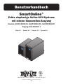
Owner’s Manual
SmartOnline
®
True On-Line Single-Phase UPS Systems
with Pure Sine Wave Output
Models: SUINT1000XLCD, SUINT2000XLCD, SUINT3000XLCD
Input: 220/230/240V
Español 32 • Français 63 • Русский 94 • Deutsch 125
1111 W. 35th Street, Chicago, IL 60609 USA • www.tripplite.com/support
Copyright © 2019 Tripp Lite. All rights reserved.

2
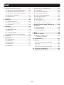
Table of Contents
1. Important Safety Warnings .....................................3
1.1 UPS Location Warnings ....................................... 3
1.2 UPS Connection Warnings................................... 3
1.3 Equipment Connections Warnings ........................ 3
1.4 Battery Warnings................................................ 3
1.5 Standard Compliance ......................................... 4
1.6 Storage............................................................. 4
2. Introduction ...........................................................4
2.1 General Overview ............................................... 4
2.2 Exterior & Dimensions ........................................ 4
2.3 Package Contents .............................................. 5
3. Operation Panel .....................................................6
3.1 LED Indicators ................................................... 6
3.2 Multi-Function Buttons ....................................... 6
3.3 LCD Display ....................................................... 7
3.4 7-Segment Display ............................................ 9
3.5 Flow Chart of the 7-Segment Display ................. 10
4. Rear Panel ...........................................................12
5. Operation Modes .................................................13
5.1 Standby Mode ................................................. 13
5.2 On-Line Mode.................................................. 13
5.3 Bypass Mode .................................................. 13
5.4 Economy Mode ................................................ 13
5.5 Battery Mode .................................................. 13
6. UPS Setup and Configuration ...............................14
6.1 Setup Menu ................................................... 14
6.2 Inverter Voltage Setup ...................................... 16
6.3 Inverter Frequency Setup .................................. 17
6.4 Frequency Conversion Setup ............................. 18
6.5 Bypass Range Setup ........................................ 19
6.6 Economy Mode Setup ...................................... 22
6.7 Alarm Setup .................................................... 22
6.8 Overload Alarm Setup ....................................... 23
6.9 External Battery Type Selection .......................... 24
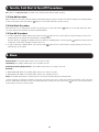
7. Turn-On, Cold Start &
Turn-Off Procedures .............................................25
7.1 Turn-On Procedure ........................................... 25
7.2 Cold Start Procedure ........................................ 25
7.3 Turn-Off Porcedure ........................................... 25
8. Alarm ................................................................... 25
9. Optional Accessories ............................................26
9.1 Additional Power Management Features ............. 26
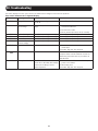
10. Troubleshooting .................................................27
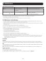
11. Maintenance ......................................................28
11.1 Maintenance Safety Warnings ....................... 28
11.2 UPS ........................................................... 28
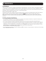
11.3 Batteries ..................................................... 29
11.4 Recycling the Used Battery ........................... 29
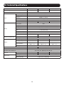
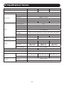
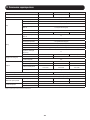
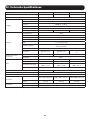
12. Technical Specifications .....................................30
13. Regulatory Compliance ......................................31

3
1. Important Safety Warnings
SAVE THESE INSTRUCTIONS
This manual contains instructions and warnings that should be followed during the installation, operation
and storage of all Tripp Lite UPS Systems. Failure to heed these warnings may affect your warranty.
1.1 UPS Location Warnings
Install the UPS system indoors, away from excess moisture or heat, conductive contaminants, dust or direct sunlight.
• Maintain the indoor temperature between 0° C and 40° C.
• Leave adequate space around all sides of the UPS for proper ventilation.
• Do not mount unit with its front or rear panel facing down (at any angle). Mounting in this manner will seriously inhibit the
unit’s internal cooling, causing product damage not covered under warranty.
1.2 UPS Connection Warnings
• Connect the UPS directly to a properly grounded AC power outlet. Do not plug the UPS into itself; this will damage the UPS.
• Do not modify the UPS system’s plug and do not use an adapter that would eliminate the UPS system’s ground connection.
• Do not use extension cords to connect the UPS to an AC outlet.
• If the UPS receives power from a motor-powered AC generator, the generator must provide clean, filtered, computer-grade
output.
• Power cables should not exceed 10 m.
1.3 Equipment Connection Warnings
• Use of this equipment in life support applications where failure of this equipment can reasonably be expected to cause the
failure of the life support equipment or to significantly affect its safety or effectiveness is not recommended. Do not use this
equipment in the presence of a flammable anesthetic mixture with air, oxygen or nitrous oxide.
• The UPS system contains its own energy source (battery). The output terminals may be live even when the UPS is not
connected to an AC supply.
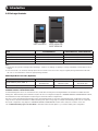
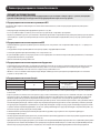
1.4 Battery Warnings
UPS Rating Built-in Batteries Battery Qty. Battery Type Battery Voltage
1kVA
Yes
2
9 Ah Sealed
Lead-Acid Battery
24V DC
2kVA 4 48V DC
3kVA 6 72V DC
• The UPS does not require routine maintenance. Do not open the UPS for any reason. There are no user-serviceable parts
inside.
• Batteries can present a risk of electrical shock and burn from high short-circuit current. Observe proper precautions. Do not
dispose of the batteries in a fire. Do not open the UPS or batteries. Do not short or bridge the battery terminals with any
object. Disconnect and turn off the UPS before performing battery replacement. Use tools with insulated handles. Battery
replacement should be performed only by authorized service personnel using the same number and type of batteries (Sealed
Lead-Acid). The batteries are recyclable. Refer to your local codes for disposal requirements or visit http://www.tripplite.com/
support/recycling-program for recycling information. Tripp Lite offers a complete line of UPS System Replacement Battery
Cartridges (R.B.C.). Visit Tripp Lite on the Web at http://www.tripplite.com/products/battery-finder/ to locate the specific
replacement battery for your UPS.
• Connect only Tripp Lite battery modules to the UPS system’s external battery hardware terminals.
• Do not operate the UPS without batteries.
• Fuses should be replaced only by factory authorized personnel. Blown fuses should be replaced only with fuses of the same
number and type.
• Potentially lethal voltages exist within this unit as long as the battery supply is connected. Service and repair should be
done only by trained personnel. During any service work, the UPS should be turned off or put into manual bypass and fuses
removed from all connected battery modules.
• Do not connect or disconnect the battery modules while the UPS is operating from the battery supply or when the unit is not
in bypass mode.

4
1.5 Standard Compliance
• CE
• EN 62040-1
• EN 62040-2 Category C2
1.6 Storage
Prior to installation
If the UPS needs to be stored prior to installation, it should be placed in a dry area. The allowable storage temperature is
between -15°C and 50°C.
After usage
Press the OFF button, make sure the UPS is shut down, disconnect the UPS from the utility power, remove all equipment
from the UPS, and store the UPS in a dry and well-ventilated area at a temperature between -15°C and 50°C. Idle batteries
must be recharged fully approximately every three months if the UPS needs to be stored for an extended period of time. The
charging time must not be less than 24 hours each time.
Note: After storage and before start-up of the UPS, allow the UPS to adjust to room temperature (20° to 25°C) for at least one hour to avoid
moisture condensation inside the UPS.
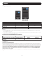
2.1 General Overview
Tripp Lite’s SUINT-Series UPS is a VFI (voltage and frequency independent) true on-line double-conversion UPS, providing
reliable and consistent sine-wave quality power to your electronic equipment. Designed to the highest quality with modern
IGBT technology, SUINT-Series UPS systems delivers a secure, reliable and uninterrupted supply of clean power to your critical
loads.
Developed with a variety of ratings and a compact footprint, the SUINT-Series delivers a high-output power factor and high
operating efficiency, providing more actual power to the attached load.
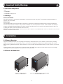
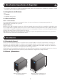
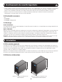
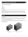
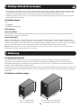
2.2 Exterior & Dimensions
225 mm
320 mm
145 mm
325 mm
390 mm
190 mm
Figure 2-1: SUINT1000XLCD
Exterior and Dimensions
Figure 2-2: SUINT2000XLCD / SUINT3000XLCD
Exterior and Dimensions
1. Important Safety Warnings
2. Introduction

5
2. Introduction
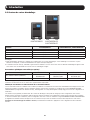
2.3 Package Contents
SUINT1000XLCD SUINT2000XLCD /
SUINT3000XLCD
Item SUINT1000XLCD SUINT2000XLCD / SUINT3000XLCD
UPS System 1 Pc. 1 Pc.
Owner's Manual 1 Pc. 1 Pc.
IEC to IEC Jumpers 2 Pc. 3 Pc.
USB Cable 1 Pc. 1 Pc.
RS232 Cable 1 Pc. 1 Pc.
Note:
1. Inspect the UPS system for damage after unpacking it. If there is any damage or anything is missing, immediately contact Tripp Lite Tech
Support.
2. If the UPS needs to be returned, carefully repack the UPS and all of the accessories using the original packing material that came with
the unit. It is recommended to retain all original packing materials.
Model-Specific Accessories (Optional)*
Model SUINT1000XLCD SUINT2000XLCD SUINT3000XLCD
External Battery Pack (LIMIT 1)
BP24V15RT2U or
BP24V28-2U
BP48V24-2U or
BP24V27-2US
BP72V15-2U or
BP72V18-2US
External Battery Pack (NO LIMIT) BP24V70RT3U BP48V60RT3U BP72V28RT3U
* Visit the specification page for your UPS system at www.tripplite.com for detailed extended runtime data and additional accessory options.
EXTERNAL BATTERY CONFIGURATION NOTE
If external battery packs are to be used with this UPS, install them following the mounting/installation documentation included with each
battery pack. External battery pack installation requires the UPS be configured via Tripp Lite’s EXTERNAL BATTERY CONFIGURATION software,
downloadable from http://www.tripplite.com/bpconfig (for all external runtime configurations).
This UPS is factory programmed with discharge curves and charging profiles for two basic external battery pack configurations accessible
using the UPS front panel LCD interface. Additional battery pack options using larger or multiple external battery packs are also supported,
but require configuration using Tripp Lite’s EXTERNAL BATTERY CONFIGURATION software and a serial port connection to the UPS.
See 5.7 External Battery Type Selection Mode to determine which method applies to your external battery pack configuration.

6
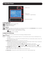
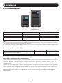
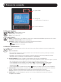
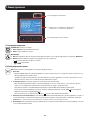
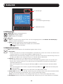
3.1 LED Indicators
GREEN LED: Indicates the output status.
1. ON (green): Output available
2. OFF: Output unavailable
RED LED:
1. ON: The UPS detects an internal fault or an environmental fault. Refer to 3.3 LCD Readout for more information.
2. Flashing: The UPS has the following warning message(s):
a. : There is no battery or battery replacement is needed.
b. : The UPS is overloaded.
3.2 Multi-Function Buttons
ON: The button has four functions. Refer to the following for detailed information:
1. Turn-On:
• In standby mode, press and hold the button for 3 seconds. Release it after one beep. The UPS will run in on-
line mode.
• Cold start: When there is no AC input, press and hold the button for 3 seconds. Release it after one beep. The
UPS will start up in battery mode.
2. Battery Test: A battery test may only be executed in on-line mode.
• To manually test the battery, press and hold the button for 3 seconds. Release it after one beep. The UPS will
transfer to battery mode and perform a 10-second battery test.
If the test result is normal, the LCD will show ‘PAS’ and the UPS will return to on-line mode.
If the test result is abnormal, the LCD will show ‘bAd’, the LED will flash and the warning icon and
no-battery/battery replacement icon will illuminate. The UPS will return to on-line mode.
3. Alarm Mute: When the alarm is on, press the button for 0.1 second to mute the alarm. The alarm will unmute
automatically when a new alarm event occurs.
Note: The alarm cannot be turned on manually after it has been disabled in setup.
4. Confirmation: In setup mode, press the button for 0.1 second to confirm parameter setup.
3.1 LED Indicators
3.3 LCD Readout
(including 3.4 7-Segment Display)
3.2 Multi-Function Buttons
3. Operation Panel

7
OFF: The button has two functions. Refer to the following for detailed information:
1. Turn-Off:
• In on-line mode, press and hold the button for 3 seconds. Release it after one beep. The inverter will be off and
the UPS will transfer to standby mode.
The UPS will keep charging the batteries in standby mode even though the button has been pressed. To fully
turn off the UPS, it is advised to unplug the input power cord.
• In battery mode, press and hold the button for 3 seconds. Release it after one beep. The UPS will turn off its
output.
2. Fault Clear:
When the UPS has a fault condition, press and hold the button for 3 seconds. Release it after one beep. The UPS
will clear the fault condition and return to standby mode. The LCD will show the relevant error code. For error code
information, refer to 3.3 LCD Readout.
SETUP: The button has two functions. Refer to the following for detailed information:
1. Scrolling down:
Press the button for 0.1 second to go to the next display.
2. Entering the setup menu:
Press the button for 3 seconds and the UPS will enter the setup menu. For more information, refer to 6.1 Setup
Menu. Please note that only qualified service personnel can perform setup actions.
Note: When the backlight of the LCD is off, press any button to wake up the display and enable each button function.
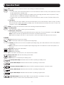
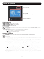
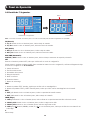
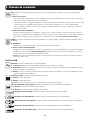
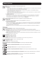
3.3 LCD
AC Icon: Indicates the input source status.
1. ON: The AC input is within the acceptable input voltage range.
2. Flashing: The AC input is out of the acceptable input voltage range, but is still sufficient to let the unit operate in
on-line mode.
3. OFF: The AC input is out of the acceptable input voltage range and is not sufficient to let the unit operate in on-
line mode.
Output Icon: Indicates the output status.
1. ON: Output available.
2. OFF: Output unavailable.
Note: In Setup Mode, the LED will be off, but output will still be available.
Battery Power Icon: Indicates the battery power status.
1. ON: On battery.
2. OFF: Output is not supplied by the battery power.
Standby Mode Graph: Illuminates when the UPS is operating in standby mode.
On-line Mode Graph: Illuminates when the UPS is operating in on-line mode.
Frequency Converter Mode: Blinks when the UPS is operating in frequency conversion mode.
Battery Mode Graph: Illuminates when the UPS is operating in battery mode.
Bypass Mode Graph: Illuminates when the UPS is operating in bypass mode.
ECO Mode Graph: Illuminates with “ECO” icon when the UPS is operating in eco mode.
Note: Frequency conversion cannot be performed while in eco mode.
3. Operation Panel
ECO

8
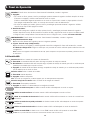
Alarm Icon: Illuminates when the alarm is disabled.
Warning Icon:
1. ON: The unit is shut down due to an internal or environmental fault. The error code will appear on the 7-segment
display. Refer to the following table for each error code and refer to 3.4 7-Segment Display for relevant
7-segment display information.
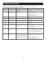
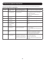
Error Code Meaning
E11 Charger Fault
E13 Temperature Out of Range
E14 +/- DC BUS High/Low
E16 Inverter Fault
E18 DC-DC Fault
E19 Abnormal Output/Inverter Voltage
E21 Output Short Circuit
Sd1 RPO Shutdown
Sd4 Battery Low Shutdown
2. Flashing: When the icon is flashing, it will be accompanied by other icon(s) to show the corresponding warning
message(s).
a. : There is no battery or battery replacement is needed.
b. : The UPS is overloaded.
Load Level Bar Graph: Indicates the load level status.
1. ON: The bar graph illuminates according to the load level *1.
2. Flashing: The bar graph flashes when there is an overload situation.
Battery Level Bar Graph: Indicates the status of battery level.
1. ON: The bar graph illuminates according to the remaining battery capacity *1.
2. Flashing: The bar graph flashes when a low-battery situation occurs.
Note: *1 means that:
<10%: no segment will illuminate.
10-29%: the first segment will illuminate.
30-49%: the first two segments will illuminate.
50-69%: the first three segments will illuminate.
70-89%: the first four segments will illuminate.
90-100%: all segments will illuminate.
3. Operation Panel

9
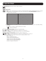
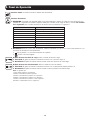
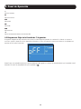
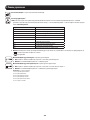
7-Segment Display
Row A
Column B
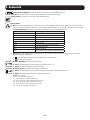
3.4 7-Segment Display
3. Operation Panel
Note: Read the text shown in Row A together with that in Column B to understand the display meaning.
IN
1. IN & V: When the two illuminate together, it indicates input voltage.
2. IN & Hz: When the two illuminate together, it indicates input frequency.
OUT
1. OUT & V: When the two illuminate together, it indicates output voltage.
2. OUT & Hz: When the two illuminate together, it indicates output frequency.
RUN TIME
RUNTIME & MIN: When the two illuminate together, it indicates the estimated remaining battery backup time.
SET
When the word ‘SET’ illuminates, it indicates the UPS is in setup mode.
You can adjust the following through the LCD. For setup instructions, refer to the Setup Mode Flow Chart in Section 5.6.
1. Inverter voltage
2. Inverter frequency
3. Frequency converter
4. Bypass range
5. Economy mode
6. Alarm disable
7. Overload alarm
TEST
1. When the word ‘TEST’ flashes, it means that the UPS is under self test.
2. When the words ‘TEST’ and ‘BATT’ flash together, it indicates the UPS is under battery self test.
BATT
1. BATT & %: When the two illuminate together, it indicates the remaining battery capacity.
2. BATT & V: When the two illuminate together, it indicates battery voltage.
LOAD
1. LOAD & %: When the two illuminate together, it indicates how much of the UPS system’s total capacity is being used.
2. LOAD & KVA: When the two illuminate together, it indicates the total load in kVA.
3. LOAD & KW: When the two illuminate together, it indicates the total load in kW.
4. LOAD & % & : When (LOAD), unit (%) and icon flash together, it indicates the UPS has an overload situation.
V
Indicates voltage.

10
%
Indicates percentage.
Hz
Indicates frequency.
kVA
Indicates kVA.
kW
Indicates kW.
MIN
Indicates minute.
°C
Indicates the UPS system’s internal temperature.
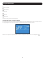
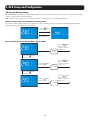
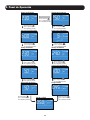
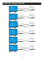
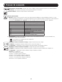
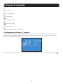
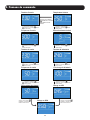
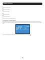
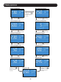
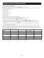
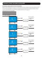
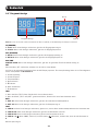
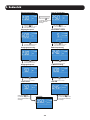
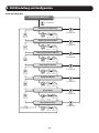
3.5 Flow Chart of the 7-Segment Display
The following flow chart shows how to go through each display screen. Below, Standby Mode is used as an example. (Each of
the display diagrams shown below is for reference only. Actual display depends on the UPS operation.)
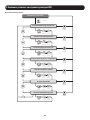
After this screen appears for approximately 10 seconds, the scrolling function will be active. The scrolling button is .
3. Operation Panel

11
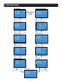
Press the button
for 0.1 second to
view the next display.
Press the button
for 0.1 second to
view the next display.
Press the button for 0.1
second to view the next display.
Press the button for 0.1
second to view the next display.
Press the button for 0.1
second to view the next display.
Press the button for 0.1
second to view the next display.
Press the button for 0.1
second to view the next display.
Press the button for 0.1
second to view the next display.
Press the button for 0.1
second to view the next display.
Press the button for 0.1
second to view the next display.
Press the button
for 0.1 second to view
the next display.
Input Voltage Internal Temperature
Input Frequency Estimated Runtime
Output Voltage Battery Voltage
Output Frequency % Battery Charge
Load Percentage
Load KVA
Load KW
24.0
0.45
0.50
3. Operation Panel

12
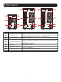
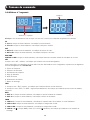
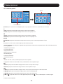
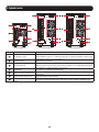
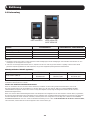
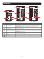
SUINT1000XLCD SUINT3000XLCDSUINT2000XLCD
1
2
3
4
5
6
1
2
3
4
5
6
7 77
1
2
3
4
5
6
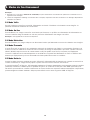
Number Item Function
1
Accessory Slot
Install an optional communication card in this slot to control and monitor the
UPS system’s status remotely via a network. See tripplite.com for current network
card options.
2
Output Sockets Connect to the loads.
3
USB Port, RS-232 Port
Connects to the computer. You can monitor the UPS system locally via your
computer by installing optional free PowerAlert software (downloadable from
www.tripplite.com/poweralert).
4
Fan(s) Cool(s) and ventilate(s) the UPS.
5
Input Breaker This is the input power’s protective device and is for safety protection.
6
AC Input Socket Connects the UPS to the mains.
7
External Battery Connector Extend battery backup runtime with the addition of optional external battery.
4. Rear Panel

13
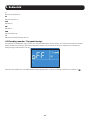
Note:
1. Refer to 3. Operation Panel for details on using the operation panel and understanding the display meaning.
2. Each of the display diagrams shown in this chapter is for reference only. Actual display depends on the UPS operation.
5.1 Standby Mode
After the UPS is connected to the AC utility, it will supply power to the UPS and the batteries will be charged. The default
setting of the UPS is ‘STANDBY mode’.
5.2 On-Line Mode
In on-line mode, the connected loads are supplied by the inverter, which derives its power from the
utility AC power. The UPS
charges the batteries and provides power protection to its connected loads.
Note: Also includes Frequency Conversion.
5.3 Bypass Mode
In bypass mode, the critical loads are directly supplied by the utility power and the batteries are charged.
5.4 Economy Mode
Economy mode refers to an optional UPS configuration for reduced power consumption and heat output. A UPS in economy mode
reduces power consumption by suspending the double-conversion (AC-to-DC / DC-to-AC) process whenever input power is already
of high enough quality to pass through to connected
equipment unchanged. The UPS will automatically switch back to on-line
mode if input power quality deteriorates to ensure connected equipment receives high-quality power under all conditions.
5.5 Battery Mode
When the UPS is operating during a power outage, the batteries’ DC power is inverted to AC and continues to provide power to
the attached load(s) until a graceful shutdown can be completed.
Tripp Lite’s PowerAlert
®
software is downloadable free of charge at www.tripplite.com/poweralert to monitor remaining battery
capacity before and during a power outage. An optional SNMP card may be used to monitor and control the UPS across a
network. Refer to www.tripplite.com/products/power-management-software-hardware~10 for more details on Tripp Lite’s
SNMP management cards.
5. Operation Modes

14
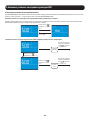
6.1 Setup Menu
Press the scrolling button for more than 3 seconds to enter the setup menu.
Note: Only qualified service personnel may perform setup actions. During setup, the following items can be adjusted:
1. Inverter voltage
2. Inverter frequency
3. Frequency converter
4. Bypass range
5. Economy mode
6. Alarm disable
7. Overload alarm
For setup procedures, refer to the following:
1. Press the scrolling button for more than 3 seconds to enter the setup menu.
2. Press the scrolling button for 0.1 second to change the parameter.
3. Press the confirmation button for 0.1 second to confirm your parameter.
4. You can skip to the next setup item by pressing the cancel button for 0.1 second.
5. In setup, press the scrolling button for more than 3 seconds. The LCD will go to the original display.
6. In setup, if no button is pressed for more than 2 minutes, the LCD will exit from the setup menu and return to the original
display.
This UPS supports a variety of advanced configuration options that can be accessed via the front panel LCD screen.
Configuration and information items include Inverter Voltage, Inverter Frequency, Frequency Conversion, Bypass Range,
Economy Mode, Alarm Setup and Overload Alarm Setup. Some settings cannot be changed in certain operation modes. Refer
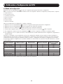
to the table below for details:
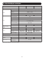
Setup Item Standby Mode On-line Mode Bypass Mode Battery Mode
Inverter Voltage Yes No Yes No
Inverter Frequency Yes No Yes No
Frequency Converter Yes No Yes No
Bypass Range Yes Yes Yes Yes
Economy Mode Yes Yes Yes Yes
Alarm Disable Yes Yes Yes Yes
Overload Alarm Yes Yes Yes Yes
Note: Only qualified service personnel may perform setup actions.
6. UPS Setup and Configuration

15
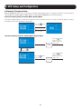
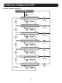
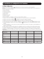
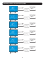
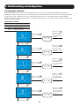
Setup Flow Chart
Original Display
T>3 seconds
T>3 seconds
T>0.1ST=0.1S
T>3 seconds
T>0.1ST=0.1S
T>3 seconds
T>0.1ST=0.1S
T>0.1S
T>3 seconds
T>0.1ST=0.1S
T>0.1S
T>3 seconds
T>3 seconds
T>0.1ST=0.1S
T>0.1S
T>0.1S
Inverter Frequency Setup
T>0.1ST=0.1S
Frequency Converter Setup
Bypass Range Setup
Alarm Setup
T>3 seconds
T>0.1ST=0.1S
T>0.1S
Economy Mode Setup
Overload Alarm Setup
Inverter Voltage Setup
T>0.1S
T>0.1S
T>0.1S
T>0.1S
T>0.1S
T>0.1S
T>0.1S
T>0.1S
6. UPS Setup and Configuration

16
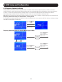
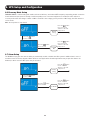
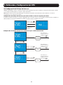
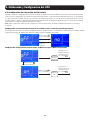
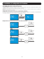
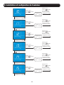
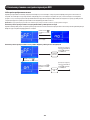
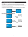
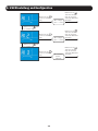
6.2 Inverter Voltage Setup
OUTPUT VOLTAGE refers to the nominal output voltage of the UPS. This value is most commonly set to match the prevailing
country or region-specific nominal voltage.
Note: Certain voltage settings will cause automatic de-rating. See specifications on unit label for de-rating info.
Inverter Voltage Setup for On-Line Mode / Battery Mode
The inverter output voltage cannot be set under the on-line or battery modes. As a result, the LCD will display a warning
message when the user attempts to set this item.
Inverter Voltage Setup for Standby Mode / Bypass Mode
Press the button
for 0.1 second
After 3 seconds
Press the button
for 0.1 second
Press the button
for 0.1 second
Press the button
for 0.1 second
Press the button
for 0.1 second
Press the button
for 0.1 second to
advance to the next
setup screen
Press the button
for 0.1 second to
advance to the next
setup screen
Press the button
for 0.1 second to
advance to the next
setup screen
Set 220V
Default
Setting
Set 240V
6. UPS Setup and Configuration

17
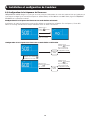
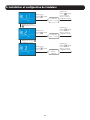
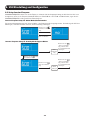
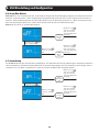
6.3 Inverter Frequency Setup
OUTPUT FREQUENCY refers to the cycles per second (Hz) of UPS output power. To configure your UPS to convert frequency
(default 50 Hz) from 50-to-60 Hz or 60-to-50 Hz, set the OUTPUT FREQUENCY to the desired setting.
Inverter Frequency Setup for On-line Mode / Battery Mode
The inverter output frequency cannot be set under the on-line or battery modes. As a result, the LCD will display a warning
message when the user attempts to set this item.
Inverter Frequency Setup for Standby Mode / Bypass Mode
Press the button
for 0.1 second
After 3 seconds
Press the button
for 0.1 second
Press the button
for 0.1 second
Press the button
for 0.1 second to
advance to the next
setup screen
Press the button
for 0.1 second to
advance to the next
setup screen
Set 60 Hz
Default
Setting
6. UPS Setup and Configuration

18
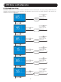
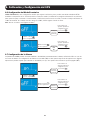
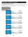
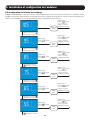
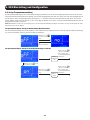
6.4 Frequency Conversion Setup
During frequency converter mode, the bypass output is disabled and the inverter output frequency is fixed as the user’s
inverter frequency setting. The inverter output frequency will not synchronize with the input frequency, even if input frequency
is within +/-3 Hz of the inverter frequency setting. If there is an internal fault, the UPS will shut down directly without
transferring to Bypass Mode. While in frequency converter mode, the output load will be derated by 30%.
Note: Remove the load from the output before setting up frequency conversion. Do not attempt to change frequency with an attached load.
Frequency Conversion Setup for On-line Mode / Battery Mode
The frequency converter cannot be set under the on-line or battery modes. As a result, the LCD will display a warning message
when the user attempts to set this item.
Press the button
for 0.1 second
After 3 seconds
Press the button
for 0.1 second
Press the button
for 0.1 second
Press the button
for 0.1 second to
advance to the next
setup screen
Press the button
for 0.1 second to
advance to the next
setup screen
Set ON
Default
Setting
Frequency Conversion Setup for Standby Mode / Bypass Mode
6. UPS Setup and Configuration

19
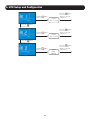
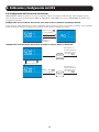
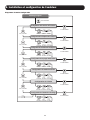
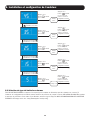
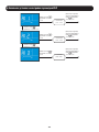
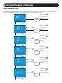
6.5 Bypass Range Setup
BYPASS RANGE: Sets the allowable voltage deviation (in percentage %) from nominal input voltage that is acceptable for
the unit to go to bypass in a fault condition. If the voltage goes outside the range, the unit will not go to bypass. If the unit
is already in bypass, it will turn the output off. The factory setting of 15% of 230V is compatible with the vast majority of
networking equipment.
Bypass Range Table
5% to 15% = -5%, +5% to -15%, +15%
HI 1 = -20% to +15%
HI 2 = -25% to +15%
HI 3 = (120V to 226V)
Press the button
for 0.1 second
Press the button
for 0.1 second
Press the button
for 0.1 second
Press the button
for 0.1 second
Press the button
for 0.1 second
Press the button
for 0.1 second
Press the button
for 0.1 second
Press the button
for 0.1 second
Press the button
for 0.1 second to
advance to the next
setup screen
Press the button
for 0.1 second to
advance to the next
setup screen
Press the button
for 0.1 second to
advance to the next
setup screen
Press the button
for 0.1 second to
advance to the next
setup screen
Set 5%
(-5% ~ +5%)
Set 6%
(-6% ~ +6%)
Set 7%
(-7% ~ +7%)
Set 8%
(-8% ~ +8%)
6. UPS Setup and Configuration
Press the button
for 0.1 second
Press the button
for 0.1 second
Press the button
for 0.1 second to
advance to the next
setup screen
Set 9%
(-9% ~ +9%)

20
Press the button
for 0.1 second
Press the button
for 0.1 second
Press the button
for 0.1 second
Press the button
for 0.1 second
Press the button
for 0.1 second
Press the button
for 0.1 second
Press the button
for 0.1 second
Press the button
for 0.1 second
Press the button
for 0.1 second
Press the button
for 0.1 second
Press the button
for 0.1 second to
advance to the next
setup screen
Press the button
for 0.1 second to
advance to the next
setup screen
Press the button
for 0.1 second to
advance to the next
setup screen
Press the button
for 0.1 second to
advance to the next
setup screen
Press the button
for 0.1 second to
advance to the next
setup screen
Set 10%
(-10% ~ +10%)
Set 11%
(-11% ~ +11%)
Set 12%
(-12% ~ +12%)
Set 13%
(-13% ~ +13%)
Set 14%
(-14% ~ +14%)
Press the button
for 0.1 second
Press the button
for 0.1 second
Press the button
for 0.1 second to
advance to the next
setup screen
Set 15%
(-15% ~ +15%)
6. UPS Setup and Configuration
La page est en cours de chargement...
La page est en cours de chargement...
La page est en cours de chargement...
La page est en cours de chargement...
La page est en cours de chargement...
La page est en cours de chargement...
La page est en cours de chargement...
La page est en cours de chargement...
La page est en cours de chargement...
La page est en cours de chargement...
La page est en cours de chargement...
La page est en cours de chargement...
La page est en cours de chargement...
La page est en cours de chargement...
La page est en cours de chargement...
La page est en cours de chargement...
La page est en cours de chargement...
La page est en cours de chargement...
La page est en cours de chargement...
La page est en cours de chargement...
La page est en cours de chargement...
La page est en cours de chargement...
La page est en cours de chargement...
La page est en cours de chargement...
La page est en cours de chargement...
La page est en cours de chargement...
La page est en cours de chargement...
La page est en cours de chargement...
La page est en cours de chargement...
La page est en cours de chargement...
La page est en cours de chargement...
La page est en cours de chargement...
La page est en cours de chargement...
La page est en cours de chargement...
La page est en cours de chargement...
La page est en cours de chargement...
La page est en cours de chargement...
La page est en cours de chargement...
La page est en cours de chargement...
La page est en cours de chargement...
La page est en cours de chargement...
La page est en cours de chargement...
La page est en cours de chargement...
La page est en cours de chargement...
La page est en cours de chargement...
La page est en cours de chargement...
La page est en cours de chargement...
La page est en cours de chargement...
La page est en cours de chargement...
La page est en cours de chargement...
La page est en cours de chargement...
La page est en cours de chargement...
La page est en cours de chargement...
La page est en cours de chargement...
La page est en cours de chargement...
La page est en cours de chargement...
La page est en cours de chargement...
La page est en cours de chargement...
La page est en cours de chargement...
La page est en cours de chargement...
La page est en cours de chargement...
La page est en cours de chargement...
La page est en cours de chargement...
La page est en cours de chargement...
La page est en cours de chargement...
La page est en cours de chargement...
La page est en cours de chargement...
La page est en cours de chargement...
La page est en cours de chargement...
La page est en cours de chargement...
La page est en cours de chargement...
La page est en cours de chargement...
La page est en cours de chargement...
La page est en cours de chargement...
La page est en cours de chargement...
La page est en cours de chargement...
La page est en cours de chargement...
La page est en cours de chargement...
La page est en cours de chargement...
La page est en cours de chargement...
La page est en cours de chargement...
La page est en cours de chargement...
La page est en cours de chargement...
La page est en cours de chargement...
La page est en cours de chargement...
La page est en cours de chargement...
La page est en cours de chargement...
La page est en cours de chargement...
La page est en cours de chargement...
La page est en cours de chargement...
La page est en cours de chargement...
La page est en cours de chargement...
La page est en cours de chargement...
La page est en cours de chargement...
La page est en cours de chargement...
La page est en cours de chargement...
La page est en cours de chargement...
La page est en cours de chargement...
La page est en cours de chargement...
La page est en cours de chargement...
La page est en cours de chargement...
La page est en cours de chargement...
La page est en cours de chargement...
La page est en cours de chargement...
La page est en cours de chargement...
La page est en cours de chargement...
La page est en cours de chargement...
La page est en cours de chargement...
La page est en cours de chargement...
La page est en cours de chargement...
La page est en cours de chargement...
La page est en cours de chargement...
La page est en cours de chargement...
La page est en cours de chargement...
La page est en cours de chargement...
La page est en cours de chargement...
La page est en cours de chargement...
La page est en cours de chargement...
La page est en cours de chargement...
La page est en cours de chargement...
La page est en cours de chargement...
La page est en cours de chargement...
La page est en cours de chargement...
La page est en cours de chargement...
La page est en cours de chargement...
La page est en cours de chargement...
La page est en cours de chargement...
La page est en cours de chargement...
La page est en cours de chargement...
La page est en cours de chargement...
La page est en cours de chargement...
La page est en cours de chargement...
La page est en cours de chargement...
La page est en cours de chargement...
La page est en cours de chargement...
La page est en cours de chargement...
-
 1
1
-
 2
2
-
 3
3
-
 4
4
-
 5
5
-
 6
6
-
 7
7
-
 8
8
-
 9
9
-
 10
10
-
 11
11
-
 12
12
-
 13
13
-
 14
14
-
 15
15
-
 16
16
-
 17
17
-
 18
18
-
 19
19
-
 20
20
-
 21
21
-
 22
22
-
 23
23
-
 24
24
-
 25
25
-
 26
26
-
 27
27
-
 28
28
-
 29
29
-
 30
30
-
 31
31
-
 32
32
-
 33
33
-
 34
34
-
 35
35
-
 36
36
-
 37
37
-
 38
38
-
 39
39
-
 40
40
-
 41
41
-
 42
42
-
 43
43
-
 44
44
-
 45
45
-
 46
46
-
 47
47
-
 48
48
-
 49
49
-
 50
50
-
 51
51
-
 52
52
-
 53
53
-
 54
54
-
 55
55
-
 56
56
-
 57
57
-
 58
58
-
 59
59
-
 60
60
-
 61
61
-
 62
62
-
 63
63
-
 64
64
-
 65
65
-
 66
66
-
 67
67
-
 68
68
-
 69
69
-
 70
70
-
 71
71
-
 72
72
-
 73
73
-
 74
74
-
 75
75
-
 76
76
-
 77
77
-
 78
78
-
 79
79
-
 80
80
-
 81
81
-
 82
82
-
 83
83
-
 84
84
-
 85
85
-
 86
86
-
 87
87
-
 88
88
-
 89
89
-
 90
90
-
 91
91
-
 92
92
-
 93
93
-
 94
94
-
 95
95
-
 96
96
-
 97
97
-
 98
98
-
 99
99
-
 100
100
-
 101
101
-
 102
102
-
 103
103
-
 104
104
-
 105
105
-
 106
106
-
 107
107
-
 108
108
-
 109
109
-
 110
110
-
 111
111
-
 112
112
-
 113
113
-
 114
114
-
 115
115
-
 116
116
-
 117
117
-
 118
118
-
 119
119
-
 120
120
-
 121
121
-
 122
122
-
 123
123
-
 124
124
-
 125
125
-
 126
126
-
 127
127
-
 128
128
-
 129
129
-
 130
130
-
 131
131
-
 132
132
-
 133
133
-
 134
134
-
 135
135
-
 136
136
-
 137
137
-
 138
138
-
 139
139
-
 140
140
-
 141
141
-
 142
142
-
 143
143
-
 144
144
-
 145
145
-
 146
146
-
 147
147
-
 148
148
-
 149
149
-
 150
150
-
 151
151
-
 152
152
-
 153
153
-
 154
154
-
 155
155
-
 156
156


Tripp Lite SmartOnline True On-Line Single-Phase UPS Systems Le manuel du propriétaire
- Catégorie
- Alimentations sans interruption (UPS)
- Taper
- Le manuel du propriétaire
dans d''autres langues
Documents connexes
-
Tripp Lite SmartOnline True On-Line Single-Phase UPS Systems Le manuel du propriétaire
-
Tripp Lite SmartOnline True On-Line Single-Phase UPS Systems Le manuel du propriétaire
-
-
-
Tripp Lite Single-Phase Online Rack UPS Le manuel du propriétaire
-
-
-
-
Tripp Lite SU3000XLCD Manuel utilisateur
-