
© 2020 HM Electronics, Inc. All rights reserved. 400Gxxx.
InstallatIon
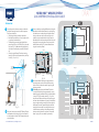
1. Survey the premises with store manager to determine
the optimal mounting locations for each component.
Take into consideration:
• Cable lengths for the hardwired components.
• Base Station accessibility to all crew members and in
an area free from obstructions.
• The Base Station mounting height should be be-
tween 4 feet (122 cm) and 5 feet (152 cm) from the
floor (see Fig. 1.1). Note: Mounting height should
also take into consideration personnel with disabili-
ties.
• Choosing a good Remote Transceiver mounting
location is critical (see Component Notes, and Step
5 with Fig. 1.3, and 1.4).
HME
BASE STATION
SIGNAL STRONGEST
DIRECTLY IN FRONT
OF REMOTE TRANSCEIVER
Fig. 1.1
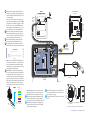
2. Set up and connect power to the AC70 Battery Charger.
Insert batteries to begin charging. Up to four batteries
can be charged at one time. See Component Notes for
more information.
NEXEO HDX™ WIRELESS SYSTEM
QUICK REFERENCE INSTALLATION GUIDE
3. If you are replacing an existing HME product, placing the
Base Station close to the Base Station you are replacing
will enable you to use the existing wires/cables without
having to route new wires. However, verify the wires/
cables are in good condition before using. Open the
Base Station and mark the mounting location on the wall
through the four mounting holes at each corner inside
the Base Station (see Fig 1.2). Mount the Base Station
using the hardware provided.
Remote
Module 1
Remote
Module 2
Remote
Module 3
Remote
Module 4
Ethernet
DC +
DC -
GND
Micro
USB
J200
J600
J201 J800 J801 J802
J805
J804
J803
J2003
J3000
J4500 J4501 J?400
J3200
J3400
J3600
J3800
1
1
1
1
1 1 1
1
1
1
1
Serial
Debug
USB
J?301
J?300
J1
Latches
Mounting
Holes
Base Station
opened
PCBA
Fig. 1.2
4. Also mount the Base Station power supply. Mark the
mounting location on the wall through the mounting
holes on each side. Mount the power supply using the
hardware provided.
5. Critical Step: Loosely mount the Remote Transceiver
in an optimal location (until range tested with a roving
headset using the Installation Wizard via the Base Station
in steps 9 & 10). For example, notice Fig. 1.3 and 1.4,
they show two different store layouts with specific target-
ed areas where the headsets are primarily used (the blue
areas are those needing coverage). Each store required
the Remote Transceiver (represented by the small blue
rectangle) to be mounted in an optimal location to pro-
vide best coverage resulting in two different mounting
locations unique to the store’s need (see “Component
Notes” on page 3 for more details on placement).
Fig. 1.3
INDOOR
SEATING AREA
OUTDOOR
SEATING AREA
KITCHEN
SHELVING
SHELVING
APPLICANCES AND
FOOD PREPARATION
MENU &
SPEAKER POST
STORAGE
COUNTER
SERVICE WINDOW
BASE
STATION
REMOTE
TRANSCEIVER
DRIVE-THRU LANE
Fig. 1.4
Present
Window
Appliance and
Food Preparation
Pay
Window
Oce
KITCHEN
Storage
Counter
Wait Areas
1 2
Sidewalk
Parking Lot
Mobile Orders
1 2
Menu &
Order
Point
Drive-Thru
Lane
Entrance
Dining/Seating Area
REMOTE
TRANSCEIVER
BASE
STATION
Typical Single Lane drive-thru store layout
QRS Aerial/Plan View
13
4
5
2

© 2020 HM Electronics, Inc. All rights reserved.
2
Fig. 2.3
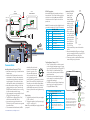
6. Install any other components required for func-
tionality such as speakers, etc. If installing a new
system with Speaker/Mic SM7000 use Fig. 2.3 as
a wiring reference.
However, if connecting to an existing system us-
ing a microphone or speaker that is not a NEXEO
component such as a DM5 microphone, or SP10
speaker, you must also use the IB7000 to make
these components compatible. Use Fig. 3.1 as a
wiring reference and see “Component Notes.”
7. Route and terminate all additional component
cables to the Base Station using the wiring refer-
ences in this guide. Consult the store’s IT person-
nel when connecting to the network router.
8. Terminate the Base Station power supply and
connect to outlet. The Base Station turns on.
9. On the Base Station UI, follow the onscreen In-
stallation Wizard to configure and test the system.
Fig. 2.1
Note: If you accidentally exit the Installation Wiz-
ard and need to return to it. LOG IN to the system,
go to SYSTEM, then the ADVANCED tab and select
“Installation” from the drop-down menu. Tap the
“Start Installation Wizard” button.
10. Critical Step: The Installation Wizard prompts
you to use a paired headset switched into Recep-
tion Location Mode. You will need to walk all ar-
eas of the store where the headset will be used to
ensure a good and continuous signal. The Boom
LED at the tip of the Headset microphone flashes
different colors to indicate areas with strong or
weak reception. This color-coded range is shown
in Fig. 2.2.
Reception/Signal
Strength
NEXEO Headset
Boom LED
VERY STRONG
STRONG
MODERATE
WEAK
NO SIGNAL
Re-pair the Headset if there
are no colors on the Boom LED
Fig. 2.2
Note: Depending on the size and layout of the
store, some stores may require more than one
Remote Transceiver to provide good coverage.
11. Test audio levels between the headsets and the
drive-thru ordering points, adjust accordingly
using the volume controls on the Base Station UI
12. Once the optimal location for the Remote Trans-
ceivers has been verified. Secure all the loosely
mounted system components.
Remote
XCVR 4
Remote
XCVR 3
Remote
XCVR 2
Remote
XCVR 1
Ethernet
DC +
DC -
GND
Micro
USB
J200
J600
J201 J800 J801 J802
J805
J804
J803
J2003
J3000
J4501 J4500
J1400
J3200
J3400
J3600
J3800
1
1
1
1
1 1 1
1
1
1
1
Serial
Debug
USB
J?301
J?300
J1
RELAY |
LOOPPLC
1
1
1
BCKP
SPKR
1 2 3 1 2
1 2 3 4 5
BK SPKR (+) - 5
BK SPKR (-) - 4
NO - 3
COM - 2
NC -1
POS - 1
NEG - 2
IN 1 - 1
IN 2 - 2
GND- 3
HME
SM7000
SPEAKER/MIC REAR VIEW
LOOP
CONNECTION
1 2 3
BK SPKR (+) - 5
BK SPKR (-) - 4
NO - 3
COM - 2
NC -1
POS - 1
NEG - 2
IN 1 - 1
IN 2 - 2
GND- 3
HME
1 2
3 4
Base Station
opened
PCBA
To NETWORK ROUTER
For CLOUD CONNECTION
48 V
BASE STATION
POWER SUPPLY
To REMOTE
TRANSCEIVER REAR
SM7000
SPEAKER/MIC REAR VIEW
LOOP
CONNECTION
RT7000 TRANSCEIVER
Front View
NOTE: Shield
must be
terminated
to GND
This Way
Up
DC+ GND DC-
13. Use cable ties to bundle and strain relief the ca-
bles exiting the Base Station to one of the cross-
bars on the rear housing.
14. Close the Base Station. The system is now ready
for use. 1 2 3 4
HME
WALL OUTLETAC70 BATTERY CHARGER
Front/Top View
POWER ADAPTER
Note: Only use the HME approved Power Adapter provided
Charging
Ports (x4)
on top
Storage
Ports (x4)
on side
6
7
8
9
10
11
12
13
14

© 2020 HM Electronics, Inc. All rights reserved. 3
Headset
Sensor
Headset
Pairing
Ring
Headset
Pairing
Ring
Headset
Pairing
Ring
Swirling Green
Pairing in progress
Solid Blue: Sensor
idle until headset is
sensed
Solid Green: Pairing
successful. Begin
using headset
Swirling Red: Pairing
unsuccessful. Try again
BASE STATION
Fig. 3.2
Fig. 3.3
Headset (AIO HS7000):
1. Install a charged
battery into the
headset (if not
already installed)
and press the power
button to turn on
(see Fig. 3.2). The
status LED blinks
green and red.
2. Pair the headset by
holding the keypad
side of the headset
against the Headset
Pairing Ring (solid
blue circle) on the
Base Station (see
Fig. 3.3). Pairing
begins automatically as soon as the headset is
sensed.
3. When the Headset Pairing Ring turns solid green,
pairing is successful (see note if pairing fails). The
Headset status LED also turns solid green.
4. Choose your position on the Base Station Home
screen and begin using the headset.
Note: If pairing fails (assuming the
headset is on, and the headset battery is
fully charged), try again. Hold the headset
steadily centered and flush against the
Headset Pairing Ring (headset movement
and distance from the Pairing Ring can
cause pairing errors).
HME
Power
Button
Battery
HEADSET
Front View
Lane 1 Lane 2
Volume Up/Unmute
Volume Down/Mute
Action Group Chat
Battery Release
Button
Remote
XCVR 4
Remote
XCVR 3
Remote
XCVR 2
Remote
XCVR 1
Ethernet
DC +
DC -
GND
Micro
USB
J200
J600
J201 J800 J801 J802
J805
J804
J803
J2003
J3000
J4501 J4500
J1400
J3200
J3400
J3600
J3800
1
1
1
1 1 1
1
1
1
1
Serial
Debug
USB
J?301
J?300
J1
1 2 3 4 5
BK SPKR +
BK SPKR -
I.D.
GND
N.C.
HME
SS7000
SPEAKER REAR VIEW
RELAY |DM5 MIC | SPKR
LOOPPLC
1
1
1
BCKP
SPKR
1 2 3 1 2
1 2 3 4 5 1 2 3 4 5 6 7
1 2 3
BK SPKR (+) - 5
BK SPKR (-) - 4
NO - 3
COM - 2
NC -1
POS - 1
NEG - 2
IN 1 - 1
IN 2 - 2
GND- 3
HME
DM5
MIC
NOTE: Shield
must be
terminated
to GND
DC+ GND DC-
1 2
3 4
Base Station
opened
PCBA
To NETWORK ROUTER
For CLOUD CONNECTION
48 V
BASE STATION
POWER SUPPLY
To REMOTE
TRANSCEIVER REAR
To REMOTE
TRANSCEIVER REAR
IB7000
REAR VIEW
LOOP
CONNECTION
RT7000 TRANSCEIVER
Front View
Fig. 3.1
IB7000 Connections:
Mount the IB7000 inside the speaker post close to
the speaker/mic. This will help minimize audio hum
and noise. As a result, do not mount the IB7000
inside the store as this will position it too far from
speaker/mic.
Note: PLC connections require the shield/drain to be
grounded (connected to pin 3 of the PLC connector).
DM5 MIC | SPKR
Pin # Label Description/wire color
1 Mic + Ext. Microphone positive (Red)
2 Mic - Ext. Microphone negative (Black)
3 GND Mic Shield (must be terminated)
4 I.D. 1-WIRE I/F (Red)
5 GND Ground (Black)
6 Spkr - Speaker negative (White)
7 Spkr + Speaker positive (Green)
Component notes
Installing the Remote Transceiver (RT7000):
• Mount the transceiver high in a central location to
headset usage.
• Maximize line of sight between the transceiver
and headsets in an area free from obstructions
and equipment/materials that can interfere with
signal propagation. These include walls, large
metal appliances, hoods, and backsplashes, etc.
• Mount the transceiver vertically on a wall in the
upright position (see arrow on Transceiver rear).
Do NOT mount horizontally such as on a ceiling,
this will reduce the transceiver’s range.
• Signal propagation is strongest directly in front of
the Transceiver and then to the sides.
• The RT7000 uses an Ethernet (Cat5 or Cat6)
cable. Do not exceed 1000’ (304 m).
• Large premises may require more than one
Transceiver. Up to four Transceivers are supported
by one Base Station.
• Once connected to the Base Station, the LED in
The Smart Battery Charger (AC70):
• The AC70 can be placed on a desk or mounted
on the wall (use the template on page 4 if mount-
ing on a wall). Position the Smart Charger (AC70)
within 10 feet (3 m) of the Base Station if you
wish to monitor your battery status via the Base
station Home screen.
• The batteries may have depleted during transit
and/or storage so we recommend you begin
charging them immediately.
• The LEDs on the Smart Charger indicate charge
status, there is one for each port (see Smart
Charger LED Reference Table).
Smart Charger LED Reference Table
Color Status/Description
Blue Charger on, Port empty
Green Flashing = Charging
Solid = Fully charged
Red
Red/
Yellow
Flashing = Unrecognized battery
Solid = Dead battery, replace battery
Flashing Red & Yellow (alternating)= Fault
condition
the middle of the circle on the
transceiver front illuminates to
indicate it is turned on. One
of the outer LEDs (numbered
1 to 4) around the circle also
turns on (depending on which
port the Transceiver is connected to on the Base
Station). This outer LED will initially flash as the
Transceiver scans for available channels before
turning solid green once a channel is found (on
the Base Station HOME screen, the Transceivers
indicator is yellow while scanning before turning
green).
Power Supply:
1. Terminate the positive wire of the power supply to
J1 (DC + terminal).
2. Terminate the negative wire of the power supply
to J1 (DC - terminal, pin 2).
Note: Only use the HME power supply provided with
your system.
1 2
3 4

© 2020 HM Electronics, Inc. All rights reserved.
4
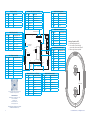
NEXEO BASE STATION PCBA
Remote
Module 1
Remote
Module 2
Remote
Module 3
Remote
Module 4
Ethernet
Telephone
Interface
Timer Greet
Veh Detect 1
Timer Greet
Veh Detect 2
Veh Detect
Inputs
Alert
Inputs
Remote
Switches
Early
Warnings
Power
In
DC +
DC -
GND
Micro
USB
J200
J600
J201 J800 J801 J802
J805
J804
J803
J2003
J3000
J4501 J4500 J1400
SW2001
J3200
J3400
J3600
J3800
1
1
1
1
1 1 1
1
1
1
1
Serial
Debug
USB
J1301
J1300
J1
Reset button to
reboot system
J600 (Ceiling Speakers)
Pin # Label Description/wire color
1 Ceiling Spkr1 + Speaker 1 positive
2 Ceiling Spkr1 - Speaker 1 negative
3 GND Ground
4 Ceiling Spkr2 + Speaker 2 positive
5 Ceiling Spkr2 - Speaker 2 negative
6 GND Ground
J4500 & J4501 (Spkr/Mic Interface)
Pin # Label Descptn/color
1 Spkr/Mic PL + Red to PLC IN1 - 1
2 Spkr/Mic PL - Black to PLC IN2 - 2
3 Shield Shield to PLC GND - 3
4 Spkr/Mic PL +
5 Spkr/Mic PL -
6 Shield
J803 (Early Warning Inputs)
Pin # Label Description/wire color
1 Early Warn In 1
2 GND Ground
3 N.C. Not used
4 Early Warn In 2
5 GND Ground
J804 (Remote Switch Inputs)
Pin # Label Description/wire color
1 GND Ground
2 Speed Team In 1
3 Operator In
4 Speed Team In 2
5 GND Ground
J805 (Alert/Alert Switch Inputs)
Pin # Label Description/wire color
1 Switch In 1
2 Switch In 2
3 Switch In 3
4 GND Ground
5 Switch In 4
6 Switch In 5
7 Switch In 6
8 GND Ground
Fig. 4.1
J201 (Telephone Interface)
Pin # Label Description/wire color
1 Tel Audio In
2 Tel Power +12V
3 Tel Off Hook
4 Tel PTT
5 Tel Ring
6 Tel Active
7 Ground
8 Tel Audio Out
J200 (Line In/Out)
Pin # Label Descptn/color
1 Line In
2 GND Ground
3 N.C.
4 Line Out
5 GND Ground
J800 and J801 (Lane 1 & 2 Timer)
Pin # Label Description/wire color
1 Greet Out
2 GND Ground
3 N.C. Not used
4 A talk Headset Lane 1/2 button
5 GND Ground
6 Rly Com Veh Det Out
7 Rly N.O. Veh Det Out
8 Rly N.C. Veh Det Out
HM ELECTRONICS, INC.
2848 Whiptail Loop, Carlsbad, CA 92010 USA
Phone: 1-800-848-4468
Fax: 858-552-0172
Website: www.hme.com
Email: [email protected]
The HME logo and product names are registered
trademarks of HM Electronics, Inc.
A copy of this guide and additional information can
be found by scanning this QR code.
J802 (Vehicle Detect Inputs)
Pin # Label Description/wire color
1 +12 V Power
2 GND Ground
3 Veh Det In 1 Vehicle Detect input
4 N.C. Not used
5 Veh Det In 2 Vehicle Detect 2 input
6 GND Ground
2”
(50.8 mm)
Mounting Template for AC70
1. Hold template against wall,
2. Use a marker to punch through
paper at the crosses to mark the wall.
3. Mount using hardware provided.

© 2020 HM Electronics, Inc. All rights reserved. 5
REGULATORY COMPLIANCE
Applicant Name: HM Electronics, Inc.
Applicant Address: 2484 Whiptail Loop, Carlsbad CA 92010, United States
Manufacturer Name: HM Electronics, Inc.
Manufacturer Address: 2484 Whiptail Loop, Carlsbad CA 92010, United States
Country of Origin: USA
Brand: HME
Caution: All products are compliant with regulatory requirements detailed in this document when the user follows all
installation instructions and operating conditions per HME specifications.
Caution: Use of accessories and peripherals other than those recommended by HME may void the product’s compliance
as well as the user’s authority to operate the equipment.
Caution: All products are designed for use with the standard, integral or dedicated (external) antenna(s) that are shipped
together with the equipment. Any product changes or modifications will invalidate all applicable regulatory certifications
and approvals.
Caution: The use of software or firmware not supported/provided by HME products may result that the equipment is no
longer compliant with the regulatory requirements.
Warning: The power adaptor is the equipment’s disconnection device. The power outlet must be
located nearby the equipment and its access must be easy.
FCC NOTICE
This device complies with Part 15 of the FCC rules. Operation is subject to the following two conditions: (1) This device
may not cause harmful interference, and (2) This device must accept any interference received, including interference that
may cause undesired operation.
NOTE: This equipment has been tested and found to comply with the limits for a Class A digital device, pursuant to Part
15 of the FCC rules. These limits are designed to provide reasonable protection against harmful interference when the
equipment is operated in a commercial environment. This equipment generates, uses and can radiate radio frequency
energy and, if not installed and used in accordance with the instruction manual, may cause harmful interference to radio
communication. Operation of this equipment in a residential area is likely to cause harmful interference, in which case the
user will be required to correct the interference at his own expense.
Changes or modifications not expressly approved by HME could void the user’s authority to operate this equipment.
FCC/IC/EC RF EXPOSURE WARNING
This product complies with FCC/IC/EC radiation exposure limits set forth for an uncontrolled environment.
Produits HME sont conformes aux limites IC d’exposition aux rayonnements définies pour un environnement non contrôlé.
This product may not be co-located or operated in conjunction with any other antenna or transmitter.
Cet appareil et son antenne (s) ne doit pas être co-localisés ou fonctionnement en association avec une autre antenne ou
transmetteur.
To comply with FCC/IC/EC RF exposure requirements, this unit must be installed and operate at least 20 cm (8 inches)
from any person.
Produits HME doivent être installés et utilisés avec distance minimum de 20cm entre le radiateur et votre corps.
INDUSTRY CANADA COMPLIANCE STATEMENT
Avis de conformité à la réglementation d’Industrie Canada
Cet appareil est conforme aux CNR d’Industrie Canada applicables aux appareils radio exempts de licence. L’exploitation
est soumise aux deux conditions suivantes:
(1) cet appareil ne doit pas provoquer d’interféence, et
(2) cet appareil doit accepter toute interféence radioéectrique subie, mêe si l’interféence est susceptible d’en comprom-
ettre le fonctionnement.
Cet éetteur exempt de licence est éuipéd’une antenne intéré. Cet éetteur exempt de licence n’est pas autoriséàfonctionner
avec une autre antenne.
Cet appareil et son antenne (s) ne doit pas être co-localisés ou fonctionnement en association avec une autre antenne ou
transmetteur.
Cet appareil numérique de la class[A] est conforme à la norme NMB-003 du Canada.
This Class[A] digital device complies with Canadian ICES-003.
KOREAN NOTICE
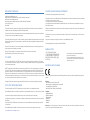
EUROPEAN UNION (CE MARK)
The CE marking indicates compliance with the following directives and standards, whenever applicable to the product in
question.
Directives:
- Radio Equipment Directive 2014/53/EU
- Electromagnetic Compatibility Directive 2014/30/EU
- Low Voltage Directive 2014/35/EU
- RoHS Directive 2011/65/EU and 2015/863/EU
Standards:
- EN55022/EN55032
- EN55024/ EN55035
- IEC/EN62368-1
- EN300328
- EN301489
- EN50581
Warning: This is a Class A product. In a domestic environment this product may cause radio interference in which case
the user may be required to take adequate measures.
Class A equipment (commercial broadcasting and
communication equipment)
This device has been tested for conformity for us in a
work environment. In a domestic environment, radio
interference may occur.

© 2020 HM Electronics, Inc. All rights reserved.
6
WASTE ELECTRICAL AND ELECTRONIC EQUIPMENT (WEEE)
The European Union (EU) WEEE Directive (2012/19/EU) places an obligation on producers (manufacturers, distributors
and/or retailers) to take-back electronic products at the end of their useful life. The WEEE Directive covers most HME
products being sold into the EU as of August 13, 2005. Manufacturers, distributors and retailers are obliged to finance
the costs of recovery from municipal collection points, reuse, and recycling of specified percentages per the WEEE require-
ments.
INSTRUCTIONS FOR DISPOSAL OF WEEE BY USERS IN THE EUROPEAN UNION
The symbol shown below is on the product or on its packaging which indicates that this product was put on the market
after August 13, 2005 and must not be disposed of with other waste. Instead, it is the user’s responsibility to dispose of
the user’s waste equipment by handing it over to a designated collection point for the recycling of WEEE. The separate
collection and recycling of waste equipment at the time of disposal will help to conserve natural resources and ensure that
it is recycled in a manner that protects human health and the environment. For more information about where you can
drop off your waste equipment for recycling, please contact your local authority, your household waste disposal service or
the seller from whom you purchased the product.
-
 1
1
-
 2
2
-
 3
3
-
 4
4
-
 5
5
-
 6
6


dans d''autres langues
- English: HME 7001 Installation guide
Documents connexes
-
HME NEXEO|HDX Crew Communication Platform Guide d'installation
-
-
HME AC70 Mode d'emploi
-
HME RT7000 REMOTE TRANSCEIVER Guide d'installation
-
-
HME EOS HD Operation Instructions Manual
-
-
-
-
