Foster MILANO ISLAND 36" 2454 900 Installation Instructions Manual
- Catégorie
- Hottes
- Taper
- Installation Instructions Manual
Ce manuel convient également à

Models covered by this instructions:
Notice d’instruction pour les modèles:
2454 900 - 2455 900
*** BEFORE INSTALLATION ***
ENSURE THERE IS NO VISIBLE OR HIDDEN DAMAGE SUSTAINED DURING SHIPPING
*** AVANT L’INSTALLATION ***
S’ASSURER QUE LES PRODUITS N’ONT SUBI AUCUN DOMMAGE PENDANT LE TRANSPORT
*** SHIPPING DAMAGE ***
MUST BE REPORTED WITHIN 5 DAYS OF RECEIPT
*** DOMMAGES DE TRANSPORT ***
DOIVENT ÊTRE NOTIFIÉS DANS LES 5 JOURS SUIVANT LA RÉCEPTION
INSTALLATION INSTRUCTIONS
INSTALLATION INSTRUCTIONS
CARE AND USE MANUAL FOR:
NOTICE D’UTILISATION ET D’ENTRETIEN POUR:
ISLAND RANGE HOODS
HOTTES ÎLOT
INSTALLATION
INSTRUCTIONS
CARE AND USE MANUAL FOR:
BUILT-IN HOODS
Models covered by this
instruction:
2458 900 (SU901)
*** BEFORE INSTALLATION
***
ENSURE THERE IS NO VISIBLE OR HIDDEN DAMAGE
SUSTAINED
DURING
SHIPPING
*** SHIPPING DAMAGE
***
MUST BE REPORTED WITHIN 5 DAYS OF RECEIPT
2458 900
HOOD MILANO ISLAND 36” 2454 900
HOOD MILANO ISLAND 48” 2455 900

WARNING
Thank you for purchasing a Foster Range Hood.
Please read all the instructions in this manual before
installing the appliance.
Save these instructions for future reference.
Only use this appliance as an exhaust ventilation system for the removal of
cooking vapors. DO NOT use to expel ammable substances or any other
materials or vapors.
The installation procedures in this manual are intended for qualied instal-
lers, service technicians or persons with similar qualied background.
DO NOT attempt to install this appliance yourself.
Ensure that electrical power is turned o at source before commencing in-
stallation. All electrical wiring must be properly installed, insulated and
grounded and conform to all applicable codes and standards.
Make sure all existing duct work is clean of grease build up, or duct work
should be replaced, if necessary, to avoid the possibility of a grease re.
Check all joints on ductwork to ensure proper connection and all joints
should be properly taped. Be careful when cutting through ceilings or walls
not to damage any hidden pipes or electrical wiring. Ensure your kitchen has
sucient air return vents to replace the exhausted air.
Fan ducts should always be vented to the outside of your home and never
into spaces within walls, ceilings, lofts or attics. Only use rigid, smooth steel
for ducting. The exhaust point of the blower requires a 6” round connec-
tion.
2

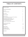
TABLE OF CONTENTS
3
BEFORE YOU BEGIN 4
MINIMUM AND MAXIMUMS 4
DUCTING 4
Duct Run Calculation 5
ELECTRICAL 5
Electrical Supply 5
INSTALLATION 6
Structural preparation for the hood fan installation 6
Fixing the Main Support Bracket 6
Attaching the range hood to the ceiling 7
Connecting Electricity and Ducting 8
Re-Circulating Requirements 8
Schematic of Classical Island Components 9
OPERATING PROCEDURES 11
General Advice 11
Functions 11
MAINTENANCE 12
Cleaning the Filter 12
Cleaning the Hood 12
Light Bulb Replacement 13
WARRANTY 14

4
BEFORE YOU BEGIN: It is advisable to test
run the range hood before installation.
BEFORE STARTING – please read this en-
tire document and ensure you are fully
conversant with the require-ments and
limitations. These units weigh approxi-
mately 125lbs and therefore require a
minimum of two people to install.
BEFORE YOU BEGIN
The manufacturer declines all responsi-
bility in the event of failure to observe the
instructions given here for installation,
maintenance and suitable operation of
the product. The manufacturer further
declines all responsibility for injury due
to negligence and the warranty of the
unit automatically expires due to impro-
per maintenance and/or installation.
MINIMUM AND MAXIMUMS
Min length of power unit structure with
deector connected = 36.6”
Min length of power unit without de-
ector = 32”.
Max length of power unit structure = 48”.
Recommended height from cook top to
underside of hood = 30” for gas, 25” for
electric.
Use the shortest most direct ductwork
route possible. Only use metal ducting
- plastic ducting is generally not permit-
ted by code. Do not use exible metal
ducting as the ridges of the ducting cau-
se severe air turbulence and will signi-
cantly reduce the eciency of any hood
-THIS TYPE OF DUCTING WILL REDUCE
EFFICIENCY BY 50%.
Vent hoods may interrupt the proper ow
of exhaust gases from re-places, gas
furnaces and gas water heaters. To mini-
mize the risk of drawing these lethal ga-
ses back into the home please follow the
heating equipment manufacturers safety
standards and guidelines. Refer to NFPA
and ASHRAE for additional information.
DUCTING
If vented externally, 6” / 150mm round
ducting must be available for the hood
through the ceiling, in line with the cen-
tral vertical axis of the range hood.
This unit must have it’s own ductwork.
Do not under any circumstances vent this
unit into any other ductwork or exhaust
ducting in the building.
PLEASE NOTE THAT THE DUCT OUTLET ON
THE TOP OF THE POWER UNIT IS OFF SET
FROM CENTRE AND THEREFORE AN ADJU-
STABLE 6” ROUND BEND WILL BE REQUIRED
TO LINE THE EXHAUST OUTLET WITH THE
6” HOLE IN THE CEILING MOUNT BRACKET.

Duct Run Calculation.
The maximum duct run before eecting
the performance of the hood is 100’. Cal-
culate your duct run by measuring linear
feet and adding the elbows, transitions
and caps based on the table below.
5
Maximum Run
6” or 3 1/4 x 10” duct 100 FT
Deduct
Each 90 elbow used 15FT
Each 45 elbow used 9FT
Each 6” or 3 1/4 x 10” duct
Transition used 1FT
Each 3’1/4 x 10” to 6”
Transition used 5FT
Side Wall with damper 30FT
Roof Cap 30FT
Electrical Supply.
This appliance requires 120V/60Hz,
3amp electrical supply – ensure an ap-
propriately qualied person completes
the electrical hook-up. The connection
point for the electrical supply is at the top
of the unit, therefore the electrical supply
must be run down from the ceiling alon-
gside the ductwork.
All electrical and venting hook-ups must
be in place before commencing installa-
tion of the hood-fan.
ELECTRICAL
WARNING: All electrical work must be
performed by a qualied electrician.
Please ensure that the appropriate electri-
cal codes or prevailing local building co-
des and ordinances are adhered to.
Ensure that the electricity supply is di-
sconnected at source. Do not use an ex-
tension cord or adapter plug with this
appliance.
This appliance must be grounded. Con-
nect to a properly grounded branch
circuit, protected by a 15 amp circuit
breaker.

6
Do not switch on the lights with the hood
at on any surface as the in-tense heat will
burn the surface and destroy the lamps.
Connect a power supply to the unit and test
all functions.
Installation of the island hood consists
of xing the ceiling Bracket A substantial
members in the ceiling. The bracket must
be xed to the frame by screwing through
the ceiling into the heavy members insi-
de the ceiling. This is critically important
as the entire hood fan hangs from this
position, and ceiling board alone will
not support the weight of the hood fan.
Discard the plastic wall plugs supplied for
xing the bracket to the ceiling – these are
not appropriate for North American struc-
tures.
Fixing the Main Support Brackets
Using Bracket “A” as a template mark the
ceiling where the xing screws “A” will be
positioned – remember the correct orien-
tation from above. Attach bracket “A” to
the ceiling permanently. If re-circulating,
attach the deector to Bracket “A” before
xing it to the ceiling – refer schematic on
page 5.
The 2 brackets for the support of the chim-
ney (Part A) is to be installed to Bracket A
with the screws. Fix the structure on the
ceiling by inserting the 2 dowels.
INSTALLATION
Structural Preparation for the Hood
Fan Installation.
The island hood weighs approximately 125
lbs. It is therefore imperative that a sub-
stantial structure is prepared in the ceiling
to attach the range hood to. Ideally block
o an area of at least 12”x12” between the
ceiling joists using 2x4’s. Allow for a hole
through the center of this blocking of at
least 6” in diameter through which to pass
the ductwork and electrical cable.
The underside of the hood must not be
closer than 30” from the cook-top and
ideally not higher than 32”above the
cook-top. It is strongly recommended, at
this point, that calculations and measure-
ments be made and all planning and hei-
ghts be nalized. You will need to t the
appropriate length of ducting to the hood
fan before installing it to the ceiling.
Planning should consist of a test assem-
bly of the power unit and telescoping
structure before attempting to mount
everything to the ceiling. By following
this test assembly you will be able to -
nalize the correct length of the assembly
before mounting it to the ceiling.
Test assembly should include actually
attaching the following items together
– refer schematic of components and
“Fixing the main support brackets”
below – Brackets A, B, C, power unit and
deector if re-circulating.
This is also a good time to test the electrical
functioning of the hood before it is instal-
led. Before switching on the light or lights,
ensure the tape holding the globes in place
has been removed.
The globes gets extremely hot and will very
quickly burn the tape and discolor the glo-
bes irreparably.

Fix Bracket “C” to the power unit with the
nuts and washers supplied (Items “A” on
the schematic on page 5). Please ensure
that the bracket is installed as shown to
enable full ac-cess to the square plastic
black box and the metal electrical junc-
tion box. Slide Bracket “B” over Bracket
“C” (once again ensure full access to the
plastic and electrical boxes is main-tai-
ned) and x it in place, at the previou-
sly calculated length using the machi-
ne screws denoted by items “B” on the
schematic on page 5.
Check that the plastic aps at the exhaust
outlet for the fan move freely and have not
become jammed during shipping or whilst
working with the power unit. Connect an
appropriate length of ducting to the unit.
Do not x the ducting to the outlet with
screws - use DUCT TAPE.
Stand the assembled structure on a clean
soft surface. Ensure the underside of the
hood does not get scratched and slide
the chimneys of the assembled structure
from the top down as per the schematic
on page 5. Ensure that the holes for -
xing the decorative chimney are correct-
ly orientated with the holes at the top of
bracket A.
Attaching the Range Hood to the Ceiling.
The entire structure that has been pre-
assembled above, must now be hoisted
up to the ceiling. A few things have to
happen at once here: the slots (as di-
scussed below) need to be engaged and
the ductwork must make connection with
the length of ductwork on the structure.
7
This will require two strong people –do
not attempt this step on your own. Brac-
ket “B” has slots, position C per Diagram
“A” (refer to page 5), at the top that will
receive the spring clips located on Bracket
“A” –THIS IS A TEMPORARY HOLD ONLY
–DO NOT RELY SOLELY ON THESE CLIPS
TO HOLD THE HOOD UP – THEY WON’T.
Once “hooked” by the spring clips imme-
diately secure the structure with the ma-
chine screws at point “E” on the schematic
on page 5 – this must be done imme-
diately and should not be skipped. Rai-
se the upper chimney to the ceiling and
x it to the bracket “A” with the screws
supplied “D”.
Ensure the entire structure is sturdy - se-
rious injury, death and MAJOR damage
could result should the unit not be well
connected to the frame structure within
the ceiling.
This is of utmost importance – do not go any
further until this has been tested and double
checked – the installer has sole responsibili-
ty for the safe installation of this product.
Attaching the Range Hood to the Ceiling.
The entire structure that has been pre-
assembled above, must now be hoisted
up to the ceiling. A few things have to
happen at once here: the slots (as discus-
sed below) need to be engaged and the
ductwork must make connection with the
length of ductwork on the structure.

This will require two strong people –do
not attempt this step on your own. Brac-
ket “B” has slots, position C per Diagram
“A” (refer to page 5), at the top that will
receive the spring clips located on Brac-
ket “A” –THIS IS A TEMPORARY HOLD
ONLY –DO NOT RELY SOLELY ON THESE
CLIPS TO HOLD THE HOOD UP – THEY
WON’T. Once “hooked” by the spring
clips immediately secure the structure
with the machine screws at point “E” on
the schematic on page 5 – this must be
done immediately and should not be
skipped.
Ensure the entire structure is sturdy- se-
rious injury, death and MAJOR damage
could result should the unit not be well
connected to the frame structure within
the ceiling.
This is of utmost importance – do not go
any further until this has been tested and
double checked – the installer has sole
responsibility for the safe installation of
this product.
Once the entire structure has been xed
to the ceiling slide the chimneys on the
assembled structure from the bottom up
as per the schematic on page 5. And x
the chimneys with the screws supplied.
Raise the upper chimney to the ceiling
and x it to the bracket “A” with the
screws supplied “D”.
Connecting Electricity and Ducting.
Make sure power is turned o at the
source. Make the electrical connection.
Test the functioning of the hood. Slide
the upper chimney into place and attach
with the machine screws provided to
Bracket “A”.
Re-Circulating Requirements.
Fit the carbon lter after the installation is
complete – these t in behind the alumi-
num grease lter.
A short length of ductwork must be con-
nected from the exhaust outlet up to the
deector (must be purchased with hood).
The deector, after attaching part B with
screws E connects to the top of Bracket
“A” and forces the air out through the
grills on the side of the chimney section
back into the room. (see diagram C).
8

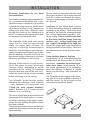
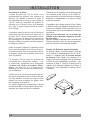
SCHEMATIC OF MODULAR ISLAND COMPONENTS
9
Diagram c
Bracket
Deector
Part B
Deector attaches to ceiling mount bracket when island hood is installed in re-circu-
lating mode and the air that has passed through the fat and carbon lters is returned
to the room via a short length of 6” round ductwork attached to the power unit and
deector.

10
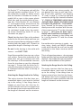
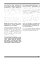
Diagram b – Securing Bracket “A” to “B”
Please note – this is critically important – do not rely on the spring clips.
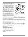
Diagram A – Main Assembly

11
FUNCTION
A: Light ON/OFF button
B: Blower Speed 1 (low) or OFF
C: Blower Speed 2 (medium)
D: Blower Speed 3 (high)
E: Blower Speed 4 (intensive)
F: 10 Minute Timer
OPERATING PROCEDURES
Read all the instructions before opera-
ting the appliance. Save these instruc-
tions for future reference.
General Advice.
Ensure that the grease lters are in place.
Without these components, operating
blowers could catch on to hair, ngers
and loose clothing. Keep fan, lters and
surfaces clean of grease and fat. Always
turn hood fan ON when cooking. NEVER
leave cooking unattended.
NEVER dispose cigarette ashes, ignitable
substances or any foreign objects into
blowers.
Cooking that generates ame is not re-
commended as this hood is equipped
with a thermal overload that will shut
down the motor if it senses excessive
heat. When frying, oil in the pan can ea-
sily overheat and ignite. Heat oil slowly
in an appropriately sized pot (covering
the entire burner) to reduce the risk of
boiling over and burning.
In the event of a range top grease re,
observe the following:
Switch OFF the range hood. Turn o
the cook top then smother ames with
a close tting lid, cookie sheet or other
metal tray. If the ames do not go out
immediately.
EVACUATE AND CALL THE FIRE DEPART-
MENT.
Never pick up a aming pan – you may
be burned. DO NOT USE WATER inclu-
ding wet dishcloths or towels, as a vio-
lent steam explosion may occur.

Cleaning the Hood.
Cleaning of the internal parts should be
done with a clean damp (not excessively
wet) cloth together with regular household
detergent. The external stainless steel ele-
ments should be cleaned with a good qua-
lity foaming stainless steel cleaner. Read
the manufacturers directions. Generally
they recommend that the foam be sprayed
onto a clean dry cloth and then applied to
the stainless steel. Allow the foam to react
on the surface for a few minutes and then
wipe with a clean dry cloth.
On the surfaces that are exposed directly
to heat from the cook-top, it is advisable
to clean these on a regular basis to avoid
the marks from becoming baked on.
Do not under any circumstances use an
abrasive type cleaner as this will scratch
and damage the stainless steel nish.
Glass components should be cleaned with
a product such as Windex.
MAINTENANCE
The hood-fan should provide many
years of trouble free service provided it
is maintained properly.
Cleaning the Filter.
Clean the grease lter either by careful-
ly hand washing, (so as not to dama-
ge the lter design) or, preferably in a
dishwasher. Depending on use, the l-
ters should be cleaned at least every two
weeks in a dishwasher.
If a carbon lter has been tted this
must be replaced at least every 6 mon-
ths as a minimum. Depending on coo-
king style and nature of cooking (greasy
foods, fry’s, curries etc) would probably
require more frequent replacement – if
odors start to manifest themselves when
cooking it is time to replace the carbon
lter . We suggest you retain a spare set.
These can be ordered from the supplier
of your range hood.
Filter requires washing indicator: after
30 hours of use, all the buttons will li-
ght up to remind you that the grease lter
should be cleaned. Follow the instruc-
tions for cleaning lters in this booklet.
Once the grease lters have been cleaned
and replaced, reset by pressing the timer
button (F). Do not rely solely on this indi-
cator. Generally, the grease lter should
be washed on a regular basis to avoid
grease lter res.
The blower should be turned on for ap-
proximately 5 minutes before cooking
in order to establish air currents upward
through the hood. Use the low speeds
for normal use and the higher speeds for
strong odors and fumes.
12

Light Replacement.
Turn blower and lights o. Make sure the
lights are cool.
Do not remove the entire xture (so-
cket) as this is very dicult to reinstall.
Visually inspect the light xture and esta-
blish whether the unit has a smooth or
“toothed” metal ring.
If smooth remove the glass blocking ring
by prying out with a sharp, soft instru-
ment such as a toothpick.
Steel instruments will scratch the surface.
Be careful that the lens does not fall out.
If “toothed”, place the tip of your nger
between the lens and the ring. Making
your way around the ring, gently pull
outwards until a point is found where the
ring pulls o .
Replace the appropriate bulb. Check par-
ts brochure or specication sheets on
our website. Wipe both sides of the glass
whilst it is out.
13

14
GENERAL CONDITIONS OF GUARANTEE
WHAT IS COVERED:
FOSTER guarantees its products for a period of 24 months from the date of original purchase
by nal customer, in both EU countries and countries outside the EU where recognized. The
purchase must be veried with a valid receipt issued by the dealer (receipt, invoice or delivery
note) that identies the purchased product, date of purchase and / or delivery of the same.
The buyer must report any esthetical defect within the rst month of purchase of the product.
The warranty covers manufacturing defects to all components except for the external piping
and / or any accessories.
WHAT IS NOT COVERED:
• Damage caused during installation of the product (reversing doors, removing screws or
brackets, adjusting feet, burners, etc.)
• Damage derived from the connection of the power, gas, water and/or electricity supply.
• Damage to knobs, handles, plastic parts, removable panels, lamps, glass parts and exter
nal rubber tubes.
• Damaged caused from accident, alteration, misuse, abuse, re, ood, acts of God, impro
per installation or use of products not approved by Foster.
• Damage to external components on which the consumer may intervene directly during
use and / or maintenance, and which may be subject to wear.
• The formation of rust and stains on the steel due to the use of unsuitable cleaning agents.
• Any functional defect indicated by the user and not conrmed during the process of veri
cation by the technician. In this case the intervention fee will be charged in full to the
consumer.
• Any parts that are Damaged from transportation not carried out by a Foster approved
carrier.
• Incorrect installation or maintenance, insucient or excessive electrical ow, plumbing
or gas abnormalities, insuciency of the chimneys, and poor fuel quality.
• Failure to follow the Foster instruction manual.
• Repair by unauthorized personnel.
• This warranty applies to appliances used in residential application; it does not cover
their use in commercial situations, which are not allowed for this product.
• Travel fees and associated charges incurred when the product is installed in a location
with limited or restricted access (i.e., isolated geographic regions located beyond 50
miles from the nearest Foster dealer).
• Also not included are service visits to:
a) Educate the customer in the proper use and care of the product.
b) Correct the installation. The customer is responsible for providing electrical wiring and/or
gas installation and other connecting facilities.
c) Reset circuit breakers or replace home fuses.

15
Should the appliance be sold by the original purchaser during the warranty period, the new
owner continues to be protected until the expiration date of the original purchaser’s warranty
period.
During the warranty period, FOSTER will replace, or repair free of charge, all components that
are defective in origin, leaving unchanged the deadline and the warranty acquired at the time
of purchase. The repair is free of charge provided it is carried out by an authorized FOSTER
Technical Assistance Centre.
If the equipment is repaired at one of the Authorised Service Centres indicated by the manu-
facturer and in the case of replacement of the product, shipping will be free of charge. In cases
where repair at home is declined, transport to and from the assistance centre will not be paid
for or provided by FOSTER.
Once the warrantee time has elapsed, the warranty becomes void and assistance will be made
by debiting the cost of the replaced parts, and the costs of labour and transportation, according
to the rates in force.
Authorized technicians will be sent in due time by FOSTER, with the desire of oering the best
service available.
FOSTER is not liable for any damages, direct or indirect, caused to people, objects and pets for
failure to follow all the instructions given in the instruction booklet and from damages resulting
from the forced suspension of the use thereof.
FOSTER will not be liable for damages arising from any repairs made by unqualied sta un-
trained by the manufacturer.
This warranty applies to appliances used in residential application; it does not cover their use
in commercial situations.
This warranty is for products purchased and retained in the 50 states of the U.S.A., the
District of Columbia and the following provinces of Canada: Quebec, Ontario, Alberta, and
British Columbia.
FOSTER DOES NOT ASSUME ANY RESPONSILITY FOR INCIDENTAL OR CONSEQUENTIAL DAMAGES.
Some states do not allow the exclusion or limitation of incidental or consequential damages, so
the above limitation or exclusion may not apply to you. This warranty gives you specic legal
rights and you may also have other rights which may vary from state to state or province to
province.
Foster Service Center
7575 E Redield Rd #129, Scottsdale, AZ 85260
Telephone (888) 639-6001
E-mail: [email protected]
Fax: (480)998-7877

INSTRUCTIONS IMPORTANTES POUR
LA SÉCURITÉ
Merci d’avoir choisi une Hotte de Cuisine Foster.
Veuillez lire attentivement toutes les instructions
avant l’installation et l’utilisation de l’appareil.
Conservez ces instructions an de pouvoir les con-
sulter au besoin.
Cet appareil est destiné à la ventilation générale seulement. NE L’UTILISEZ
PAS pour évacuer des vapeurs ou des substances dangereuses ou explosi-
ves.
Conez l’installation et les réparations uniquement à un professionnel, con-
formément aux normes de sécurité en vigueur.
N’ESSAYEZ PAS d’installer cet appareil par vous-même.
Avant l’installation veillez que l’appareil soit hors tension.
Tout le câblage électrique doit être correctement installé, isolé de mise à la
terre conformément aux codes et aux normes applicables.
Assurez-vous que les conduits d’évacuation sont propres et libres d’accu-
mulation de graisses ou remplacez les conduits pour éviter de provoquer un
incendie.
Vériez que tous les joints du conduit sont bien xés et scellés. Faites atten-
tion lors des travaux de maçonnerie de ne pas endommager des tuyaux ou
câbles électriques. Assurez-vous que votre cuisine est équipée de bouches
de ventilation qui évacuent l’air vicié.
Le conduit de ventilation doit toujours terminer à l’extérieur et jamais dans
des espaces clos, plafonds ou greniers. Pour le conduit utilisez seulement
des éléments rigides en acier lisse.
La sortie de la souante nécessite d’un conduit rond de 6”.
16

TABLE DES MATIÈRES
AVANT DE COMMENCER 18
MINIMUM ET MAXIMUM 18
CONDUIT 18
Calcul Longueur Conduit 19
ÉLECTRICITÉ 19
Alimentation Électrique 19
INSTALLATION 20
Préparation Placement de la Hotte 20
Fixation Étrier de Support Principal 20
Fixation de la Hotte au Plafond 21
Branchement Électrique et Conduit 22
Mode Recyclage 22
Schéma des Composants de la Hotte Îlot Classique 23
PROCÉDURES D’UTILISATION 25
Recommandations Générales 25
Fonctions 25
ENTRETIENT 26
Nettoyage des Filtres 26
Nettoyage de la Hotte 26
Replacement lumière 27
GARANTIE 31
17

AVANT DE COMMENCER : On recommande de
vérier le fonctionnement de la hotte avant
son installation.
AVANT DE COMMENCER – lisez attentivement
cette notice an d’avoir les connaissances requi-
ses pour utiliser ce produit. Ce produit pèse env.
125lbs et nécessite donc un minimum de deux
personnes pour son installation.
AVANT DE COMMENCER
Le fabricant décline toute responsabilité en
cas de dommages causés par un non respect
des instructions d’installation, d’utilisation et
d’entretien contenues dans cette notice. Le
fabricant décline toute responsabilité causée
par négligence et la garantie cesse automa-
tiquement en cas de mauvais entretien et/ou
installation du produit.
MINIMUM ET MAXIMUM
Longueur minimale de la structure du groupe
d’alimentation avec déecteur = 36.6”
Longueur minimale du groupe d’alimentation
sans déecteur = 32”
Longueur maximale de la structure du groupe
d’alimentation = 48”
Distance recommandée entre la table de cuis-
son et la partie inférieure de la hotte = 30”
pour table de cuisson gaz, 25” pour table de
cuisson électrique.
Cherchez la voie la plus directe vers l’extérieur.
Utilisez seulement des tuyaux rigides en métal
- les tuyaux en plastiques sont interdit par le
code. N’utilisez pas des conduits métalliques
exibles, du moment que le bord du con-
duit peut provoquer des fortes turbulences et
réduire considérablement le rendement de la
hotte - CE TYPE DE CONDUIT RÉDUIT LE REN-
DEMENT DU 50%.
Les hottes peuvent empêcher la bonne éva-
cuation des fumées des cheminées, des fours
et des chaue-bains à gaz. An de minimiser
le risque que ces gaz mortels peuvent retour-
ner dans la maison, observez les normes de
sécurité et les directives en vigueur.
Consultez les normes NFPA et ASHRAE pour
plus d’informations.
CONDUIT
Si votre hotte à une évacuation d’air vers l’ex-
térieur, le conduit qui passe par le plafond
doit mesurer 6” / 150mm et être en ligne
avec l’axe centrale de la hotte.
Cet appareil doit avoir son propre con-
duit. La hotte ne doit pas être raccordée à
d’autres conduits d’évacuation de combu-
stion présents dans votre immeuble.
SI LA SORTIE DU CONDUIT DE LA PARTIE
SUPÉRIEURE DU GROUPE ALIMENTATION N’EST
PAS CENTRÉE, UTILISEZ UN COUDE ROND RÉ-
GLABLE DE 6” POUR ALIGNER LA SORTIE D’AIR
AVEC LE TROU DE 6” DANS LE SUPPORT DE
MONTAGE A PLAFOND.
18

Calcul Longueur Conduit
La longueur maximale du conduit qui n’inue
pas sur le rendement de la hotte est de 100”.
Calculez la longueur du conduit en mesurant
les pieds linéaires et en ajoutant les coudes,
les raccords et les bouchons selon le schéma
suivant.
Langueur maximale
6” ou 31/4x10” conduit 100 FT
Chaque coude 90 nécessite 15FT
Chaque coude 45 nécessite 9FT
Chaque 6” ou 31/4x10” conduit
Raccord nécessite 1FT
Chaque 3’1/4x10” à 6”
Raccord nécessite 5FT
Paroi latérale avec clapet anti retour 30FT
Sortie toit 30FT
Alimentation Électrique.
Cet appareil nécessite 120V/60Hz, une ali-
mentation de 3amp – faites eectuer le bran-
chement électrique par une personne qualiée.
La connexion pour l’alimentation électrique
se trouve au sommet de l’appareil, par con-
séquent, le courant doit descendre le long du
conduit.
Avant d’installer la hotte, tous les travaux de
branchement électrique et d’évacuation des
fumées doivent être eectués.
ÉLECTRICITÉ
ATTENTION : Tous les travaux électriques
doivent être eectués par un électricien
qualié.
An d’assurer la qualité des travaux de con-
struction et d’électricité observez les normes
en vigueur.
Assurez-vous que l’alimentation électrique
est coupée. Evitez d’utiliser une rallonge ou
un adaptateur pendant cette opération.
Cet appareil doit être mis à la terre et le cir-
cuit doit être protégé par un disjoncteur de
15 amp.
19

N’allumez pas les lumières avec la hotte appuyée
sur n’importe quelle surface, car la chaleur in-
tense peut brûler la surface et briser les lampes.
Branchez un alimentateur à la hotte et testez
toutes les fonctions.
L’installation de la hotte consiste à xer l’étrier
à plafond A dans les éléments résistants qui se
trouvent au plafond. L’étrier doit être xé à la
structure avec des vis et aux éléments résistants
du plafond.
Cela est très important, car le panneau de
plafond seul ne peut pas supporter le poids
de cette hotte.
Jetez les chevilles en plastique pour la xation de
l’étrier au plafond, car ils ne sont pas appropriés
pour les structures de l’Amérique du Nord.
Fixation des Étriers de Support Principaux
En utilisant l’étrier A comme gabarit, marquez
sur le plafond le positionnement des vis de -
xation A – rappelez-vous la correcte position
du dessous. Fixez l’étrier A au plafond. Si la
hotte est en mode recyclage, xez le déecteur
à l’étrier A avant l’installation au plafond – voir
schéma à la page 5. Fixez les 2 étriers pour le
support de la cheminée (élément A) à l’étrier A
avec les vis. Fixez l’appareil au plafond par les
2 chevilles.
INSTALLATION
Placement de la Hotte.
La hotte îlot pèse env. 125 lbs. Donc, il est
indispensable de préparer une structure au
plafond sur laquelle accrocher la hotte. Il
est préférable de circonscrire une surface de
12”x12” entre les poutrelles du plafond en
utilisant 2x4’s. Prévoir un trou d’un diamètre
min. de 6” à travers lequel passent le conduit
et le câblage.
La distance entre le dessous de la hotte et la
table de cuisson doit mesurer au moins 30” et
pas plus de 32”. Nous recommandons forte-
ment, à ce point, de faire tous les calcules et
les mesurages et de naliser les plans et les
hauteurs. Reliez le conduit à la hotte avant de
l’installer au plafond.
Avant de monter l’appareil au plafond, testez
le bon fonctionnement de la hotte et la struc-
ture télescopique. Ainsi vous pouvez mesurer
la longueur exacte de l’ensemble avant de la
xer au plafond.
Ce montage d’essai inclut le montage de
l’ensemble des composants suivants – voir
le schéma des composants et le paragraphe
« Fixation des Étriers de Support Princi-
paux » : les étriers A, B, C, le groupe d’ali-
mentation et, pour la hotte en mode recycla-
ge, le déecteur.
Vériez aussi le bon fonctionnement électri-
que avant d’installer la hotte. Avant d’allumer
la ou les lumières, assurez-vous que le ruban
adhésif qui tient ensemble les globes dans
leur logement a été enlevé.
Les globes deviennent extrêmement chauds
et peuvent brûler le ruban adhésif en endom-
mageant les globes de façon irréparable.
20
La page est en cours de chargement...
La page est en cours de chargement...
La page est en cours de chargement...
La page est en cours de chargement...
La page est en cours de chargement...
La page est en cours de chargement...
La page est en cours de chargement...
La page est en cours de chargement...
La page est en cours de chargement...
La page est en cours de chargement...
La page est en cours de chargement...
La page est en cours de chargement...
-
 1
1
-
 2
2
-
 3
3
-
 4
4
-
 5
5
-
 6
6
-
 7
7
-
 8
8
-
 9
9
-
 10
10
-
 11
11
-
 12
12
-
 13
13
-
 14
14
-
 15
15
-
 16
16
-
 17
17
-
 18
18
-
 19
19
-
 20
20
-
 21
21
-
 22
22
-
 23
23
-
 24
24
-
 25
25
-
 26
26
-
 27
27
-
 28
28
-
 29
29
-
 30
30
-
 31
31
-
 32
32


Foster MILANO ISLAND 36" 2454 900 Installation Instructions Manual
- Catégorie
- Hottes
- Taper
- Installation Instructions Manual
- Ce manuel convient également à
dans d''autres langues
- English: Foster MILANO ISLAND 36" 2454 900
