MENU SYSTEM MANUAL
HANDLEIDING MENUSYSTEEM
MANUEL D’UTILISATION ET DE PARAMETRAGE
MANUALE DI SISTEMA DEI MENU
MENÚ DEL MANUAL DEL SISTEMA

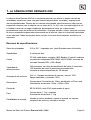
This product is marked with the CE symbol and indicates
compliance with all applicable directives.
Directive 89/336/EEC.
A “Declaration of Conformity” is held at Dedicated Micros Ltd.,
11 Oak Street, Swinton, Manchester, M27 4FL.

Contents
1. THE DENNARD 2060 DOME CAMERA 3
2. THE DENNARD 2040 DOME CAMERA 5
3. PROGRAMMABLE FEATURES 7
3.1 Preset Positions 7
3.2 Preset Position Titles 7
3.3 Tours 7
3.4 Real Time Clock 7
3.5 Alarm Response 7
3.6 Bottom Flip 8
3.7 Camera Mode 8
3.8 Digital Zoom Extension 8
3.9 Dome Selection Cursor 8
3.10 Text Positioning and Selection 8
3.11 Joystick Range 8
3.12 Host polling 8
3.13 Error Reporting 9
3.14 Activity light 9
3.15 User Timeout 9
3.16 Set Video Amplification 9
3.17 Privacy mode 9
4. OPERATION WITH A CONTROL PANEL 10
4.1 Dome Menu Structure with Dennard controllers 10
4.2 Main Menu 11
4.2.1 Go to Preset or Start Tour 11
4.2.2 PIN number entry 12
4.3 Supervisor Menu 15
4.3.1 Store/Edit Preset 15
4.3.2 Store/Edit Tour 16
4.3.3 Alarm Setup 17
Dennard 2040 / 2060 Menu System Manual Page. 1

4.3.4 Supervisor Options 19
4.3.5 Enter New PIN 22
4.3.6 Privacy Zone Setup 22
4.4 Technician Menu 23
4.4.1 Camera set up 23
4.4.2 Enable/Disable options 24
4.4.3 Joystick control 24
4.4.4 Miscellaneous Services 25
4.4.5 Enter New PIN 26
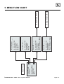
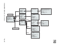
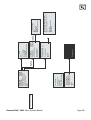
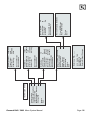
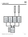
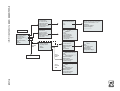
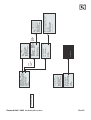
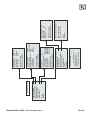
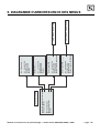
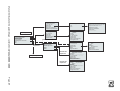
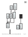
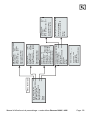
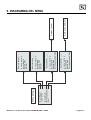
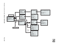
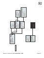
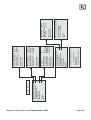
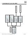
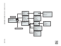
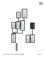
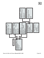
5. MENU FLOW CHART 27
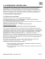
6. ALTERNATIVE CONTROLLERS 31
6.1 Dedicated Micros Digital Sprite 2 31
6.1.1 Up the coax control 31
6.1.2 RS485 control 32
6.2 Baxall / Vista controllers 32
6.3 Dennard dtx1000/dc 33
6.4 Building Block Video TX1000/DC 34
6.5 Dennard dtx400/dc 35
6.6 Building Block Video TX400DC 36
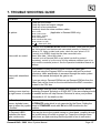
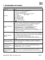
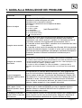
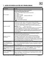
7 TROUBLE SHOOTING GUIDE 37
Dennard 2040 / 2060 Menu System Manual Page. 2

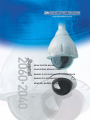
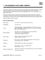
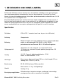
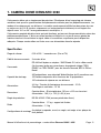
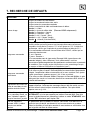
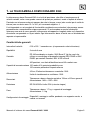
1. THE DENNARD 2060 DOME CAMERA
The Dennard 2060 Dome Camera is a precision unit, offering a wide variable speed range, together
with a large pre-set memory for positions, tours and alarm responses. It has a switchable
colour/monochrome camera (colour-only on indoor units) with an 18:1 or 26:1 zoom lens plus x 4
digital enhancement.
The unit has a comprehensive set of features as standard, which can be tailored for individual
preferences. These can be accessed through an internally generated set of menus overlaid on the
video signal if the controller does not have a suitable layout. Each Dome Camera is delivered with a
separate weatherproof power supply.
Outline Specification:
Dennard 2040 / 2060 Menu System Manual Page. 3
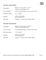
Speed range 0.05 to 300° / second max (both Pan and Tilt)
Repeatability 5 minutes of arc
Control
RS 485 half duplex or simplex, 9600 Baud OR ‘Up the coax’ using
built in DEN PANEL or BAX PANEL protocol converter for Dennard,
BBV & DM or Baxall controls
Storage capacity
200 positions, with identifying title of up to 20 characters
100 tours of up to 16 preset positions
100 deep alarm response memory
Power Supply
24Va.c, Camera & control electronics:-10VA
Heater & blower unit:-10VA
Dimensions
Dome Camera: 150mm diameter hemisphere x 230mm overall
Power Supply: 165L x 135W x 95H.
Protection BS EN 60529 to level IP66 (no water ingress)
Weight
Dome Camera: 1.7 kg + mounting bracket
Power Supply: 1.3 kg
Mounting Configurations
Ceiling mount, pendant mount, wall bracket, corner mount, snowdrop
& tile mounts available

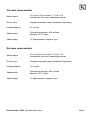
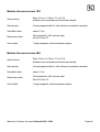
18X zoom camera module
26X zoom camera module
Dennard 2040 / 2060 Menu System Manual Page. 4
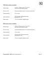
Optical range
4.1mm to 73.8mm zoom; F1.4 to F3.0
Auto-focus with manual override
Privacy zones 24 programmable zones (8 on screen at any time)
Video sensitivity 0.7 lux colour
Video resolution
768 horizontal x 494 vertical pixels
More than 470 TVL
Video output 1.0v p-p composite, negative synch
Optical range
3.5mm to 91.0mm zoom; F1.6 to F3.8
Auto-focus with manual override
Privacy zones 24 programmable zones (8 on screen at any time)
Video sensitivity 1.0 lux colour
Video resolution
768 horizontal x 494 vertical pixels
More than 470 TVL
Video output 1.0v p-p composite, negative synch

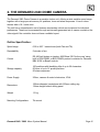
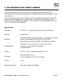
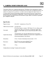
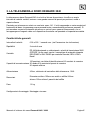
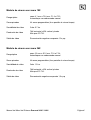
2. THE DENNARD 2040 DOME CAMERA
The Dennard 2040 Dome Camera is a precision indoor unit, offering a wide variable speed range,
together with a large pre-set memory for positions, tours and alarm responses. It has a colour
camera with a 18:1 zoom lens.
The unit has a comprehensive set of features as standard, which can be tailored for individual
preferences. These can be accessed through an internally generated set of menus overlaid on the
video signal if the controller does not have a suitable layout.
Outline Specification:
Dennard 2040 / 2060 Menu System Manual Page. 5
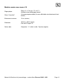
Speed range 0.05 to 300° / second max (both Pan and Tilt)
Repeatability 5 minutes of arc
Control
RS 485 half duplex or simplex, 9600 Baud OR 'Up the coax' using
built in DEN PANEL or BAX PANEL protocol converter for Dennard,
BBV & DM or Baxall controls
Storage capacity
100 positions with identifying title of up to 20 characters
50 tours of up to 16 preset positions
50 alarm responses
Power Supply 24Va.c, camera & control electronics; 10VA
Dimensions
150mm diameter hemisphere with 220mm ceiling ring
110mm height behind ceiling panel
Weight 1.5 kg
Mounting Configurations Tile mount.

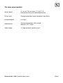
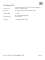
18X zoom camera
Dennard 2040 / 2060 Menu System Manual Page. 6
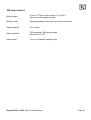
Optical range
4.1mm to 73.8mm optical zoom; F1.4 to F3.0
Auto focus with manual override
Privacy zones 24 programmable zones with 8 on screen at any time
Video sensitivity 3 Lux colour
Video resolution
768 horizontal x 494 vertical pixels
More than 470 TVL
Video output 1.0v p-p composite, negative sync

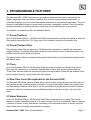
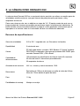
3. PROGRAMMABLE FEATURES
The Dennard 2040 / 2060 Camera's have a number of features which can be selected by the
System Supervisor when the dome is installed. Any of these can be altered subsequently, or
cancelled altogether, to give the best operational responses for any particular application. They are
invoked or cancelled through on-screen menu structures, described in section 4, and the settings
are then retained in non-volatile memory so that they are not affected by a loss of power.
The features, and what they offer, are described below:
3.1 Preset Positions
Up to 200 (Dennard 2060) or 100 (Dennard 2040) positions can be stored and recalled at any time.
Each position stores the Pan, Tilt, Zoom, and Focus positions as well as the position title.
3.2 Preset Position Titles
Each preset position title can have up to 20 alphanumeric characters to identify the associated
position uniquely. The default title position lies at the top left hand corner of the video picture, left
justified, but this can be altered if required.
The preset position titles only appear at the position they identify: any movement from that position
will remove them.
3.3 Tours
Up to 100 (Dennard 2060) or 50 (Dennard 2040) tours can be stored and recalled at any time.
Each tour can contain up to 16 positions together with a ‘Dwell’ time at each position plus the
‘Travel Time’ that the dome unit must take to reach the next position. When the last position in the
tour is reached, the tour ‘loops’ back to the first position.
3.4 Real Time Clock (Not applicable to the Dennard 2040)
The Dennard 2060 dome camera is fitted with a real time clock to provide time and date marks for
the operator and the recording system if required. A range of selectable formats can provide time
and date displays and the unit is able to use the information to provide enhanced alarm functions
where the reaction to an alarm can be modified depending on the time of day or the day of the
week.
3.5 Alarm Response
Up to 100 (Dennard 2060) or 50 (Dennard 2040) Alarm responses can be stored. Each alarm
response creates a specified reaction to an alarm number. This is a very powerful feature, allowing
a number of domes, or any other device conforming to the Dennard protocol, to invoke a pre-set
alarm action from one single loop broadcast command.
Dennard 2040 / 2060 Menu System Manual Page. 7

3.6 Bottom Flip
The dome will automatically pan through 180 degrees as fast as possible when tilted fully down so
that it is possible to follow a person or car, moving directly underneath the dome, with only a single
joystick direction to consider.
3.7 Camera Mode
The camera in both Dennard 2060 and Dennard 2040 can be switched between colour and
monochrome mode. In the Dennard 2060 it can be selected as colour/mono in which case it will
automatically switch to mono when the light level is insufficient for good quality colour pictures.
3.8 Digital Zoom Extension
The camera system allows an extension of the optical zoom by selecting more of the central part of
the picture and expanding this to fill the frame. This feature is selectable.
3.9 Dome Selection Cursor
The menu structure itself, and the choices and selections offered, are searched and invoked by a
single cursor or flashing character and the direction in which this moves depends on the particular
control panel in use. The direction of movement can be reversed separately for horizontal and
vertical movement if required.
3.10 Text Positioning and Selection
All text can be positioned where it is wanted, replaced with default text (eg: Position 31, or Sector
18), or removed as required.
3.11 Joystick Range
Even if the control panel has a wide range proportional joystick output, the dome has such a wide
speed range that both a fast and a slow speed range are needed to realise the full performance
(provided of course that the control panel in question has a facility to invoke these separately).
The slow speed range is simply the same as the fast speed range following the same in-built
correlation law, but divided by a constant. This constant can be set between 2 and 128.
3.12 Host polling
When the dome is configured for communication using RS485 protocols it can be set to check its
communication link at regular intervals. If a continuous data stream is expected from the controller,
enabling Host Polling will get the dome to report a communications error if nothing is received for 5
seconds. Normally, this setting is disabled.
Dennard 2040 / 2060 Menu System Manual Page. 8

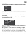
3.13 Error Reporting
The dome constantly monitors its own health and is able to indicate that a problem has occurred by
a flashing square in the top right hand corner of the transmitted picture. The cause can
subsequently be requested when convenient. Alternatively, the unit can display the error text
instead of the flashing square.
3.14 Activity light
A green LED provides some diagnostic help when first switching the dome on and also indicates
when command signals are received. As it may be visible externally it can be switched on or off.
3.15 User Timeout
There is a possibility that the dome may be left pointing at an unhelpful scene and, for whatever
reason, ‘forgotten’. To cater for this eventuality, two settings have the specific function of acting to
prevent this happening. These are Preset 001 and Tour 001.
A time delay can be set between 1 and 999 seconds and a default response to the timeout being
reached also defined. If the time is exceeded after any joystick/key entry Pan and Tilt input at the
Control Panel then the default action will occur.
If a delay time of 0 is set, no default action will occur and the unit will wait indefinitely for the next
user input.
If a dome menu screen is left waiting for an input for more than 3 minutes then the system times
out and the dome resumes its previous activity.
3.16 Set Video Amplification
This facility allows the video gain to be adjusted from the normal setting, with four levels available.
Video lift can be tuned on or off and is normally set to the Off position.
3.17 Privacy mode
It is sometimes desirable to prevent operators from viewing certain areas. To meet this requirement
the Privacy mode allows black patches to be set up to cover these areas.
The size of the patch overlaid is the size of the monitor view at whatever zoom setting is used.
When zooming out, the patch reduces in size so that it only covers the original area.
Dennard 2040 / 2060 Menu System Manual Page. 9

4. OPERATION WITH A CONTROL PANEL
NB: This will vary between control panels. Please refer to the Controller manual.
The Dome Camera's are open protocol devices. Consequently, there are several different
manufacturers’ controllers available to drive it. All of the many features offered by the dome are
programmed from one of three menu structures. Each controller will have individual control
configurations which make it essential that the user reads the controller manual to ascertain which
button activation gives access to the menu features. Section 6 gives these functions for several
popular controllers.
The following instructions will guide you through the menu structure when using the Dome & PSU
(with address set to No. 253… DEN PANEL) controlled by either a Dennard dtx400dc or dtx1000dc
4.1 Dome Menu Structure with Dennard controllers
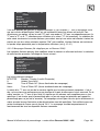
The Menus appear on the screen when activated by the following commands:
Note that the ‘shift’ key must be held down while the selection is made.
On activation, the menu will appear on the monitor screen against the normal video scene
background with a cursor on the left hand edge. A choice is made by positioning the cursor over the
desired feature and operating an “ACCEPT” button(s) which, for the Dennard controllers, is as
follows:-
For Dennard dtx1000dc, hold the preset button and press CAMERA SELECT 1
For Dennard dtx 400dc, press preset 1 button
Dennard 2040 / 2060 Menu System Manual Page. 10
Dennard dtx1000dc
access
Dennard dtx400dc
access
User Menu shift wash shift 1
Supervisor Menu (password required) shift wipe shift 2
Technicians Menu (password required) shift autopan shift 3

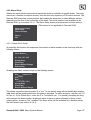
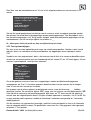
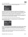
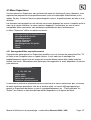
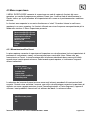
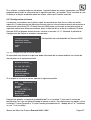
4.2 Main Menu
When called, the Main Menu screen will display the following options, against a camera display
background, with a cursor at the left hand edge:
Using the joystick, or direction arrow keys, move up or down the list to select the feature required
then press the appropriate key(s) to accept/select it. If ‘Exit’ is chosen the menu is cleared and no
other action is taken by the dome.
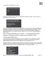
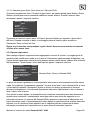
4.2.1 Go to Preset or Start Tour
These selections allow the operator to recall the full range of stored Preset positions and Tours,
even if the control panel has neither the numerical range nor general ability to do so.
Note that this screen only allows existing preset positions and tours to be accessed. To set
up new presets or tours, see section 4.3.1 or 4.3.2
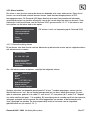
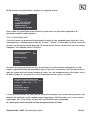
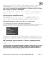
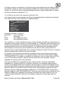
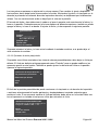
The display will prompt for the required numerical entry with the following subsidiary menu:
The cursor can be moved across the numerical line, using the joystick or control buttons, until the
desired number is reached. The characters will flash their position in turn and, as soon as one is
selected with the ACCEPT button(s), will be displayed in the _ _ _ part of the display.
Leading zeros need not be entered (eg 001 may be entered simply as ‘1’) but the entry must be
within range, eg 001 - 250 for Presets and 001 - 100 for Tours (Dennard 2060) and 001 - 100 for
Presets and 001 - 50 for Tours (Dennard 2040). Entries outside the range will cause an ‘Illegal
Entry’ message to flash, and the entry must be cleared and re-entered.
When the digits have been selected, Accept Entry will invoke that choice and the screen will
automatically clear to the desired camera position.
Dennard 2040 / 2060 Menu System Manual Page. 11
Go to Preset
Start Tour
Technician Menu
Supervisor Menu
Exit
Preset Number___ (orTourNumber)
0123456789
Accept Entry
Clear Entry
Return

To change the choice, ‘Clear Entry’ will start the process again.
Note that Preset number 1 and Tour number 1 should be allocated to the most common or
important views. These values are the ones to which the dome automatically returns
following a power cut if no operator is in attendance. See the section on power fail, sec
4.4.2.
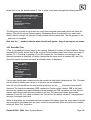
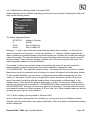
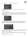
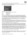
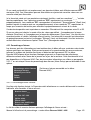
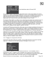
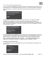
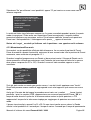
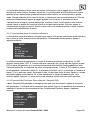
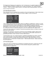
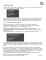
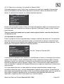
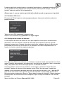
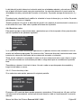
4.2.2 PIN number entry
When the Technician or Supervisor menu is called the following screen appears. The password
or PIN Number is keyed in using the same method as used with previous entries.
The cursor is run across the numerical line, using the joystick or control buttons, until the desired
number is reached. The characters will flash their position in turn and as soon as one is selected
with the ACCEPT button(s) it will be displayed in the _ _ _ _ part of the display.
When all four digits have been selected, Accept Entry will invoke that choice and the screen will
automatically change to the selected menu i.e. the Technician or Supervisor menu.
Dennard 2040 / 2060 Menu System Manual Page. 12
Enter PIN____
0123456789
Accept Entry
Clear Entry
Cancel

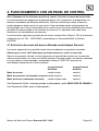
THE FACTORY SET PASSWORDS (PINs), WHICH CAN BE
CHANGED BY THE TECHNICIAN OR SUPERVISOR IN THEIR
RESPECTIVE MENUS, ARE PRINTED BELOW.
TO PREVENT UNAUTHORISED CHANGES BEING MADE TO
SETTINGS OR STORED CAMERA POSITIONS, IT IS ADVISED
THAT PIN NUMBERS ARE KEPT IN A SAFE PLACE.
IF IT IS FELT NECESSARY, CUT THIS PAGE OUT OF THE
MANUAL.
Dennard 2040 / 2060 Menu System Manual Page. 13
To gain access to the Supervisor Menu, enter PIN as ‘1111’
To gain access to the Technician Menu, enter PIN ‘9999’

THIS PAGE IS INTENTIONALLY LEFT BLANK
Dennard 2040 / 2060 Menu System Manual Page. 14

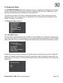
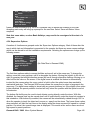
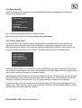
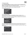
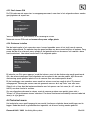
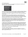
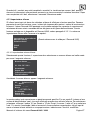
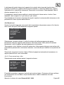
4.3 Supervisor Menu
The SUPERVISOR MENU allows the supervisor not only to duplicate the operator menu functions,
but also to programme Preset positions (with their identifying title) and Tours. Additionally, cursor
setting and text positioning and selection are accessed here.
The functions are split into a series of underlying menus in ‘layers’. When returning from most
underlying menus, the overlying menu is re-presented. The functions which are less likely to be
needed lie deeper in the structure.
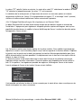
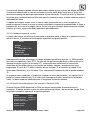
The Supervisor Menu displays:
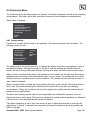
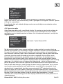
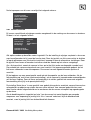
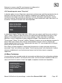
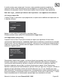
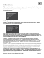
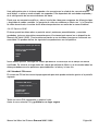
4.3.1 Store/Edit Preset
The first option enables the supervisor to define a view (including pan, tilt and zoom settings) and
store it for future recall. Note that storing a Preset requires that the desired camera view is already
visible when this screen is entered. Selecting this option calls up the following underlying screens.
Selecting the preset number is achieved as with the previous numerical entry screens. When the
number is accepted, a new display will allow the supervisor to give this position a name (such as
‘Main Gate’ or ‘Front Door’) or use the default names stored in the dome software. The screen will
prompt with:
Edit Preset Text -
Yes
No
Preset Number___
0123456789
Accept Entry
Clear Entry
Return Without Change
Delete Preset
Store/Edit Preset
Store/Edit Tour
Alarm Setup
Supervisor Options
Change PIN
Privacy Zone Setup
Return
Exit
Dennard 2040 / 2060 Menu System Manual Page. 15

Select ‘No’ to use the default names or ‘Yes’ to enter a new name through the following screen.
The title choice is made as usual with the cursor and accepted when ready (which will store the
chosen Title with the stored Preset position). Backspace allows a correction to be made while
‘Return without change’ will store the Preset position with the default title. The title appears in the _
_ space as it is compiled.
Note that the ‘_’ symbols indicate where the title will appear - they do not appear on-screen
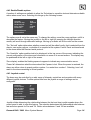
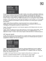
4.3.2 Store/Edit Tour
A Tour is a predefined journey taken by the camera, between a number of Preset positions. Before
accessing this facility, ensure that all the required Preset positions have been stored, as shown in
section 4.3.1. Choosing to program a Tour first requires the Tour Number to be entered in an
identical procedure to selecting a Position (except that the range must lie between 001 and 100).
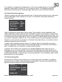
Once the number has been accepted, a subsidiary menu is displayed:
If a tour has already been established on this number its initial data is displayed as ‘Old’. This data
can be edited by adding new values or a new tour can be established.
Here the entry format follows the now-familiar procedure but the _ _ _ characters have specific
functions: The first three characters, PPP, represent a Preset position number. ‘DD’ is the dwell
time that the camera must spend stationary at that position and ‘SS’ represents the time that the
camera must take to reach the next position in the tour. The times are entered as seconds,
between 01 and 99. If no value is entered, the Tour will use the default values of 2 seconds dwell
time and 3 seconds travel time.
When all characters are completed and then accepted, the display clears the entry ready to receive
the next position information and the ‘Item’ counter is incremented. When all entries are complete,
select the ‘Store Tour’ instruction.
Dennard 2040 / 2060 Menu System Manual Page. 16
ABCDEFGHIJKLMNOPQRSTUVWX
YZabcdefghijklmnopqrstuv
wxyz0123456789:/*=+.-
Backspace
Return Without Change
Accept Entry
____________
Item ___intour___
PPPDDTT
Old_______
New_______
0123456789
Accept Entry
Clear Entry
Return Without Change
Store Tour

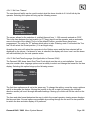
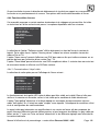
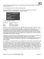
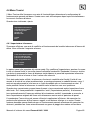
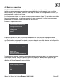
4.3.3 Alarm Setup
Alarms are inputs into the dome which require the dome to undertake a specific action. They may
come from a number of external sources, such as door entry systems or PIR motion sensors. The
Dennard 2060 dome has a clock function that enables the supervisor to select different actions
depending on the time of day or the day of the week. This clock function is not available in the
Dennard 2040, go to section 4.3.3.1. The Alarm Setup screen provides access to three options:
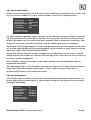
4.3.3.1 Alarm Action Setup
On selecting this function the supervisor must select an alarm number in the usual way with the
following screen:
Accepting the Alarm number brings up the following screen:
This allows a specified preset position P or tour T to be stored, along with its identification number
‘nnn’ which will be implemented when the alarm is activated. To select an option, use the code ‘01’
for Tour or ‘10’ for Preset (the 1 under the P or T selects its use; 11 is invalid). Accepting the entry
will increment the alarm number allowing all inputs to have an action allocated to them or their
existing action, shown as ‘Old’, modified. The alarm action will be sustained for a duration set by
the user timeout (see section 4.3.4.1).
Dennard 2040 / 2060 Menu System Manual Page. 17
Alarm Action Setup
Mask Alarm
Select Holidays
Return
Exit
Alarm Number___
01234567890
Accept Entry
Clear Entry
Return Without Change
Delete Alarm
Alm___Select P or T
PTnnn
Old____
New____
0123456789
Accept Entry
Clear Entry
Return Without Change
(This screen is not applicable to Dennard 2040)

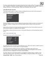
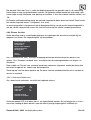
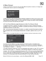
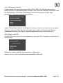
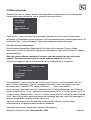
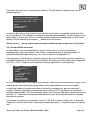
4.3.3.2 Mask Alarms (Not Applicable to Dennard 2040)
Alarm responses can be modified, depending on when they are activated. Selecting this facility will
bring up the following screen:
The letters displayed indicate:
MTWTFSS Monday to Sunday
H Holiday
hhmm Time of ‘Mask On’
hhmm Time of ‘Mask Off’
Entering a ‘1’ under a day of the week means that the alarms will be masked – i.e. they will not
cause a response from the dome – on that day. Similarly, a ‘1’ under the Holiday means that the
alarm is masked on specified holidays (note that the setting for a holiday will override the setting for
a day of the week). The mask will operate throughout the days selected unless a mask on and off
time are entered. This is achieved through numerical entry of the time using the 24hr clock. The
mask temporarily disables all connected alarms.
For example, if motion sensors have been connected into the dome but are only required to
operate outside of normal working hours they can be masked by entering the code
‘1111100008301800’. This masks the alarms on Mon – Fri between 08.30 a.m and 6 p.m. Outside
these times, and at the weekends and on holidays, the dome will respond to the alarms as desired.
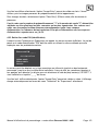
To add complete flexibility, up to ten levels of configuration are available, indicated by the ‘Item
number’ on the screen. As each entry is accepted the number increments until the full action is
saved. Secondary levels allow different masking times to be selected on different days. In the
example above, it may be that the building closes early on Friday. To achieve the different times,
the first code (item) would be modified to ‘1111000008301800’ and a second item code entered as
‘0000100008301400’. Now, the first mask only applies from Monday to Thursday while the second
level masks the alarms on Fridays, between 8.30 a.m. and 2 p.m. More complex masks can be built
up using the same logic for more variations.
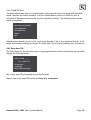
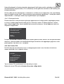
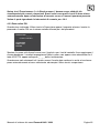
4.3.3.3 Select Holidays (Not Applicable to Dennard 2040)
Up to 15 days can be programmed in as holidays, to cover periods such as Christmas or Bank
Holidays, when the alarm action may require modification. When the option is selected the following
screen is displayed:
Dennard 2040 / 2060 Menu System Manual Page. 18
Item___ofAlarm Mask
PTWTFSSHhhmmhhmm
Old______________
New____
0123456789
Accept Entry
Clear Entry
Return Without Change
Save and Return
__________
La page est en cours de chargement...
La page est en cours de chargement...
La page est en cours de chargement...
La page est en cours de chargement...
La page est en cours de chargement...
La page est en cours de chargement...
La page est en cours de chargement...
La page est en cours de chargement...
La page est en cours de chargement...
La page est en cours de chargement...
La page est en cours de chargement...
La page est en cours de chargement...
La page est en cours de chargement...
La page est en cours de chargement...
La page est en cours de chargement...
La page est en cours de chargement...
La page est en cours de chargement...
La page est en cours de chargement...
La page est en cours de chargement...
La page est en cours de chargement...
La page est en cours de chargement...
La page est en cours de chargement...
La page est en cours de chargement...
La page est en cours de chargement...
La page est en cours de chargement...
La page est en cours de chargement...
La page est en cours de chargement...
La page est en cours de chargement...
La page est en cours de chargement...
La page est en cours de chargement...
La page est en cours de chargement...
La page est en cours de chargement...
La page est en cours de chargement...
La page est en cours de chargement...
La page est en cours de chargement...
La page est en cours de chargement...
La page est en cours de chargement...
La page est en cours de chargement...
La page est en cours de chargement...
La page est en cours de chargement...
La page est en cours de chargement...
La page est en cours de chargement...
La page est en cours de chargement...
La page est en cours de chargement...
La page est en cours de chargement...
La page est en cours de chargement...
La page est en cours de chargement...
La page est en cours de chargement...
La page est en cours de chargement...
La page est en cours de chargement...
La page est en cours de chargement...
La page est en cours de chargement...
La page est en cours de chargement...
La page est en cours de chargement...
La page est en cours de chargement...
La page est en cours de chargement...
La page est en cours de chargement...
La page est en cours de chargement...
La page est en cours de chargement...
La page est en cours de chargement...
La page est en cours de chargement...
La page est en cours de chargement...
La page est en cours de chargement...
La page est en cours de chargement...
La page est en cours de chargement...
La page est en cours de chargement...
La page est en cours de chargement...
La page est en cours de chargement...
La page est en cours de chargement...
La page est en cours de chargement...
La page est en cours de chargement...
La page est en cours de chargement...
La page est en cours de chargement...
La page est en cours de chargement...
La page est en cours de chargement...
La page est en cours de chargement...
La page est en cours de chargement...
La page est en cours de chargement...
La page est en cours de chargement...
La page est en cours de chargement...
La page est en cours de chargement...
La page est en cours de chargement...
La page est en cours de chargement...
La page est en cours de chargement...
La page est en cours de chargement...
La page est en cours de chargement...
La page est en cours de chargement...
La page est en cours de chargement...
La page est en cours de chargement...
La page est en cours de chargement...
La page est en cours de chargement...
La page est en cours de chargement...
La page est en cours de chargement...
La page est en cours de chargement...
La page est en cours de chargement...
La page est en cours de chargement...
La page est en cours de chargement...
La page est en cours de chargement...
La page est en cours de chargement...
La page est en cours de chargement...
La page est en cours de chargement...
La page est en cours de chargement...
La page est en cours de chargement...
La page est en cours de chargement...
La page est en cours de chargement...
La page est en cours de chargement...
La page est en cours de chargement...
La page est en cours de chargement...
La page est en cours de chargement...
La page est en cours de chargement...
La page est en cours de chargement...
La page est en cours de chargement...
La page est en cours de chargement...
La page est en cours de chargement...
La page est en cours de chargement...
La page est en cours de chargement...
La page est en cours de chargement...
La page est en cours de chargement...
La page est en cours de chargement...
La page est en cours de chargement...
La page est en cours de chargement...
La page est en cours de chargement...
La page est en cours de chargement...
La page est en cours de chargement...
La page est en cours de chargement...
La page est en cours de chargement...
La page est en cours de chargement...
La page est en cours de chargement...
La page est en cours de chargement...
La page est en cours de chargement...
La page est en cours de chargement...
La page est en cours de chargement...
La page est en cours de chargement...
La page est en cours de chargement...
La page est en cours de chargement...
La page est en cours de chargement...
La page est en cours de chargement...
La page est en cours de chargement...
La page est en cours de chargement...
La page est en cours de chargement...
La page est en cours de chargement...
La page est en cours de chargement...
La page est en cours de chargement...
La page est en cours de chargement...
La page est en cours de chargement...
La page est en cours de chargement...
La page est en cours de chargement...
La page est en cours de chargement...
La page est en cours de chargement...
La page est en cours de chargement...
La page est en cours de chargement...
La page est en cours de chargement...
La page est en cours de chargement...
La page est en cours de chargement...
La page est en cours de chargement...
La page est en cours de chargement...
La page est en cours de chargement...
La page est en cours de chargement...
La page est en cours de chargement...
La page est en cours de chargement...
La page est en cours de chargement...
La page est en cours de chargement...
La page est en cours de chargement...
La page est en cours de chargement...
La page est en cours de chargement...
La page est en cours de chargement...
La page est en cours de chargement...
La page est en cours de chargement...
La page est en cours de chargement...
La page est en cours de chargement...
La page est en cours de chargement...
La page est en cours de chargement...
La page est en cours de chargement...
La page est en cours de chargement...
La page est en cours de chargement...
La page est en cours de chargement...
La page est en cours de chargement...
La page est en cours de chargement...
La page est en cours de chargement...
La page est en cours de chargement...
La page est en cours de chargement...
La page est en cours de chargement...
La page est en cours de chargement...
La page est en cours de chargement...
La page est en cours de chargement...
La page est en cours de chargement...
La page est en cours de chargement...
-
 1
1
-
 2
2
-
 3
3
-
 4
4
-
 5
5
-
 6
6
-
 7
7
-
 8
8
-
 9
9
-
 10
10
-
 11
11
-
 12
12
-
 13
13
-
 14
14
-
 15
15
-
 16
16
-
 17
17
-
 18
18
-
 19
19
-
 20
20
-
 21
21
-
 22
22
-
 23
23
-
 24
24
-
 25
25
-
 26
26
-
 27
27
-
 28
28
-
 29
29
-
 30
30
-
 31
31
-
 32
32
-
 33
33
-
 34
34
-
 35
35
-
 36
36
-
 37
37
-
 38
38
-
 39
39
-
 40
40
-
 41
41
-
 42
42
-
 43
43
-
 44
44
-
 45
45
-
 46
46
-
 47
47
-
 48
48
-
 49
49
-
 50
50
-
 51
51
-
 52
52
-
 53
53
-
 54
54
-
 55
55
-
 56
56
-
 57
57
-
 58
58
-
 59
59
-
 60
60
-
 61
61
-
 62
62
-
 63
63
-
 64
64
-
 65
65
-
 66
66
-
 67
67
-
 68
68
-
 69
69
-
 70
70
-
 71
71
-
 72
72
-
 73
73
-
 74
74
-
 75
75
-
 76
76
-
 77
77
-
 78
78
-
 79
79
-
 80
80
-
 81
81
-
 82
82
-
 83
83
-
 84
84
-
 85
85
-
 86
86
-
 87
87
-
 88
88
-
 89
89
-
 90
90
-
 91
91
-
 92
92
-
 93
93
-
 94
94
-
 95
95
-
 96
96
-
 97
97
-
 98
98
-
 99
99
-
 100
100
-
 101
101
-
 102
102
-
 103
103
-
 104
104
-
 105
105
-
 106
106
-
 107
107
-
 108
108
-
 109
109
-
 110
110
-
 111
111
-
 112
112
-
 113
113
-
 114
114
-
 115
115
-
 116
116
-
 117
117
-
 118
118
-
 119
119
-
 120
120
-
 121
121
-
 122
122
-
 123
123
-
 124
124
-
 125
125
-
 126
126
-
 127
127
-
 128
128
-
 129
129
-
 130
130
-
 131
131
-
 132
132
-
 133
133
-
 134
134
-
 135
135
-
 136
136
-
 137
137
-
 138
138
-
 139
139
-
 140
140
-
 141
141
-
 142
142
-
 143
143
-
 144
144
-
 145
145
-
 146
146
-
 147
147
-
 148
148
-
 149
149
-
 150
150
-
 151
151
-
 152
152
-
 153
153
-
 154
154
-
 155
155
-
 156
156
-
 157
157
-
 158
158
-
 159
159
-
 160
160
-
 161
161
-
 162
162
-
 163
163
-
 164
164
-
 165
165
-
 166
166
-
 167
167
-
 168
168
-
 169
169
-
 170
170
-
 171
171
-
 172
172
-
 173
173
-
 174
174
-
 175
175
-
 176
176
-
 177
177
-
 178
178
-
 179
179
-
 180
180
-
 181
181
-
 182
182
-
 183
183
-
 184
184
-
 185
185
-
 186
186
-
 187
187
-
 188
188
-
 189
189
-
 190
190
-
 191
191
-
 192
192
-
 193
193
-
 194
194
-
 195
195
-
 196
196
-
 197
197
-
 198
198
-
 199
199
-
 200
200
-
 201
201
-
 202
202
-
 203
203
-
 204
204
-
 205
205
-
 206
206
-
 207
207


Dedicated Micros 2060 Le manuel du propriétaire
- Taper
- Le manuel du propriétaire
- Ce manuel convient également à
dans d''autres langues
- italiano: Dedicated Micros 2060 Manuale del proprietario
- español: Dedicated Micros 2060 El manual del propietario
- Nederlands: Dedicated Micros 2060 de handleiding
Documents connexes
-
Dedicated Micros 2060 PTZ Dome Mode d'emploi
-
Dedicated Mircros Dennard 2060 Le manuel du propriétaire
-
-
-
-
Dedicated Micros Digital Sprite 2 Guide d'installation
-
-
-
Dedicated Mircros 2025 Infra-Red LED Illuminator Guide d'installation
-