Spectrum Controls 2080sc-NTC Le manuel du propriétaire
- Taper
- Le manuel du propriétaire

User’s Manual Pub. 0300331-02 Rev. A
Micro800TM 4-Channel Universal
Thermistor Input Module
Catalog Number: 2080sc-NTC

ii 2080sc-NTC 4-Channel Universal Thermistor Input Module
User’s Manual Pub 0300331-02 Rev. A
Important Notes
1. Please read all the information in this owner’s guide before installing the
product.
2. The information in this owner's guide applies to hardware Series A and
firmware version 1.1 or later.
3. This guide assumes that the reader has a full working knowledge of the
relevant processor.
Notice
The products and services described in this owner's guide are useful in a wide
variety of applications. Therefore, the user and others responsible for applying
the products and services described herein are responsible for determining their
acceptability for each application. While efforts have been made to provide
accurate information within this owner's guide, Spectrum Controls, Inc. assumes
no responsibility for the accuracy, completeness, or usefulness of the information
herein.
Under no circumstances will Spectrum Controls, Inc. be responsible or liable for
any damages or losses, including indirect or consequential damages or losses,
arising out of either the use of any information within this owner's guide or the
use of any product or service referenced herein.
No patent liability is assumed by Spectrum Controls, Inc. with respect to the use
of any of the information, products, circuits, programming, or services referenced
herein.
The information in this owner's guide is subject to change without notice.
Limited Warranty
Spectrum Controls, Inc. warrants that its products are free from defects in
material and workmanship under normal use and service, as described in
Spectrum Controls, Inc. literature covering this product, for a period of 1 year.
The obligations of Spectrum Controls, Inc. under this warranty are limited to
replacing or repairing, at its option, at its factory or facility, any product which
shall, in the applicable period after shipment, be returned to the Spectrum
Controls, Inc. facility, transportation charges prepaid, and which after
examination is determined, to the satisfaction of Spectrum Controls, Inc., to be
thus defective.
This warranty shall not apply to any such equipment which shall have been
repaired or altered except by Spectrum Controls or which shall have been subject
to misuse, neglect, or accident. In no case shall the liability of Spectrum
Controls, Inc. exceed the purchase price. The aforementioned provisions do not
extend the original warranty period of any product which has either been repaired
or replaced by Spectrum Controls, Inc.

User’s Manual Pub 0300331-02 Rev. A
Table of Contents
IMPORTANT NOTES ................................................................................................................................................. II
NOTICE ..................................................................................................................................................................... II
LIMITED WARRANTY ................................................................................................................................................ II
TABLE OF CONTENTS ............................................................................................................................................... III
PREFACE .................................................................................................................................................................. IV
MODULE OVERVIEW........................................................................................................................... 1-1
SECTION 1.1 GENERAL DESCRIPTION .......................................................................................................................... 1-1
1.1.1 What is it? ............................................................................................................................................. 1-1
1.1.2 How does it connect mechanically? ....................................................................................................... 1-1
1.1.3 How does it connect via software? ........................................................................................................ 1-1
1.1.4 How does it indicate normal function? .................................................................................................. 1-1
SECTION 1.2 ......................................................................................................................................................... 1-2
SECTION 1.3 \ ENVIRONMENT AND ENCLOSURE............................................................................................................ 1-2
SECTION 1.4 PREVENT ELECTROSTATIC DISCHARGE ....................................................................................................... 1-4
SECTION 1.5 PARTS LIST .......................................................................................................................................... 1-4
SECTION 1.6 HARDWARE FEATURES ........................................................................................................................... 1-5
SECTION 1.7 MODULE POWER SPECIFICATIONS ............................................................................................................. 1-6
SECTION 1.8 MODULE CHASSIS EARTH GROUND.......................................................................................................... 1-6
INSTALLATION AND WIRING .............................................................................................................. 2-1
SECTION 2.1 INSERT MODULE INTO CONTROLLER ......................................................................................................... 2-1
SECTION 2.2 CONFIGURATION TAGS ........................................................................................................................... 2-3
SECTION 2.3 NEW CONFIG TRIGGER (S1_CFG_TRIGGER) .............................................................................................. 2-4
SECTION 2.4 CONFIGURATION BITS (S1_CFG_CH_N_PARMS[0])................................................................................... 2-4
SECTION 2.5 DATA FORMAT ..................................................................................................................................... 2-5
2.5.1 EU×1 ..................................................................................................................................................... 2-5
2.5.2 EU×10 ................................................................................................................................................... 2-5
2.5.3 Raw Proportional .................................................................................................................................. 2-5
2.5.4 Equation................................................................................................................................................ 2-5
SECTION 2.6 ADD THE NTC TO CCW ......................................................................................................................... 2-7
SECTION 2.7 MODULE ID......................................................................................................................................... 2-9
2.7.1 Module Error Register (MOD_STATUS) ................................................................................................ 2-10
SECTION 2.8 2080SC-NTC EXAMPLE STRUCTURED TEXT .............................................................................................. 2-13
SECTION 2.9 TECHNICAL ASSISTANCE ........................................................................................................................ 2-16
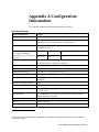
APPENDIX A CONFIGURATION INFORMATION ..................................................................................................... A-1
HAZARDOUS LOCATION CONSIDERATIONS .................................................................................................................... A-4
ENVIRONNEMENTS DANGEREUX ................................................................................................................................ A-5
INDEX ..................................................................................................................................................................... I-1

iv 2080sc-NTC 4-Channel Universal Thermistor Input Module
User’s Manual Pub. 0300331-02 Rev. A
Preface
Read this preface to familiarize yourself with the rest of the manual. This preface
covers the following topics:
• Who should use this manual
• How to use this manual
• Rockwell Automation technical support
• Documentation
• Conventions used in this manual
Who Should
Use This Manual
Use this manual if you are responsible for designing, installing, programming, or
troubleshooting control systems that use Allen-Bradley I/O and/or compatible
controllers, such as CompactLogix and ControlLogix.
How to Use
This Manual
As much as possible, we organized this manual to explain, in a task-by-task
manner, how to install, configure, program, operate, and troubleshoot a control
system using the Micro800™ 2080sc-NTC 4-Channel Universal Thermistor
Input Module.
Rockwell
Automation
Technical
Support
For technical support, please contact your local Rockwell Automation
TechConnect Office for all Spectrum products. Contact numbers are as follows:
• USA 1-440-646-6900
• United Kingdom 01-908-635-230
• Australia 1-800-809-929
• Mexico 001-888-365-8677
• Brazil 55-11-3618-8800
• Europe +49-211-41553-630
or send an email to support@spectrumcontrols.com

2080sc-NTC 4-Channel Universal Thermistor Input Module v
User’s Manual Pub 0300331-02 Rev. A
Documentation
If you would like a .PDF version of a manual, you can download a free electronic
version at www.spectrumcontrols.com.
Conventions
Used in This
Manual
The following conventions are used throughout this manual:
• Bulleted lists (like this one) provide information not procedural steps.
• Numbered lists provide sequential steps or hierarchical information.
• Italic type is used for emphasis.
• Bold type identifies headings and sub-headings:
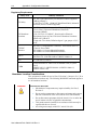
WARNING
Identifies information about practices or circumstances that can lead to
personal injury or death, property damage, or economic loss. Attentions
help you to identify a hazard, avoid a hazard, and recognize the
consequences.
ATTENTION
Actions ou situations risquant d’entraîner des blessures pouvant être
mortelles, des dégâts matériels ou des pertes financières. Les messages
« Attention » vous aident à identifier un danger, à éviter ce danger et en
discerner les conséquences.
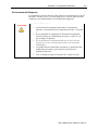
NOTE
Identifies information that is critical for successful application and
understanding of the product.

vi 2080sc-NTC 4-Channel Universal Thermistor Input Module
User’s Manual Pub. 0300331-02 Rev. A

User’s Manual Pub. 0300331-02 Rev. A
Module Overview
Section 1.1
General
Description
1.1.1 What is it?
The Micro800™ 2080sc-NTC 4-Channel Analog Input Module is a
thermistor/resistance input module designed for use for use with Rockwell
Automation Micro800™ systems. This module is optimized for Negative
Temperature Coefficient (NTC) thermistors for temperature measurement. The
module interfaces with the controller via an Asynchronous Parallel Interface
(API) which it shares with other plug-in peripherals in the controller. Power is
provided across the same connector used to implement the API.
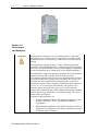
1.1.2 How does it connect mechanically?
The module plugs into any spare plug-in slot on the PLC. A 40-pin connector
provides the connection between the controller and the module.
Thermistor/Resistance input connections are connected to the module via a 12-
pin terminal block on the module.
1.1.3 How does it connect via software?
The exchange of data between the module and controller is used to communicate
module configuration, status and digitized samples from the four analog inputs.
Other types of exchanges also occur across the API. These exchanges include
reset commands by the controller, interrupts from the module to the controller,
module status queries by the controller, configuration changes and other
associated communications.
The plug-in module contains memory with specific locations holding
configuration, status, and channel values accessible to the controller as register
locations.
1.1.4 How does it indicate normal function?
The module has a single green LED which is ON for normal operation and blinks
in the case of a fault detected by the module.
The 2080sc-NTC module uses a 20-bit, Sigma-Delta, analog-to-digital converter
to achieve 16-bit resolution. All inputs have fault tolerance and ESD protection
to avoid damage to circuitry on the board.
The module operates in normal run mode when installed in a Micro800 controller
chassis and is powered on and is designed to operate 24 hours a day, 7 days a
week, for a period of years.

1-2 Chapter 1: Module Overview
User’s Manual Pub. 0300331-02 Rev. A
Section 1.2
Environment
and Enclosure
WARNING
This equipment is intended for use in a Pollution Degree 2 industrial
environment, in overvoltage Category II applications (as defined in IEC
publication 60664-1), at altitudes up to 2000 meters (6562 feet) without
derating.
This equipment is considered Group 1, Class A industrial equipment
according to IEC/CISPR Publication 11. Without appropriate precautions,
there may be potential difficulties ensuring electromagnetic compatibility
in other environments due to conducted as well as radiated disturbance.
This equipment is supplied as open-type equipment. It must be mounted
within an enclosure that is suitably designed for those specific
environmental conditions that will be present and appropriately designed
to prevent personal injury resulting from accessibility to live parts. The
enclosure must have suitable flame-retardant properties to prevent or
minimize the spread of flame, complying with a flame spread rating of 5
VA, V2, V1, V0 (or equivalent) if non-metallic. The interior of the
enclosure must be accessible only by the use of a tool. Subsequent
sections of this publication may contain additional information regarding
specific enclosure type ratings that are required to comply with certain
product safety certifications.
In addition to this publication, see:
• Industrial Automation Wiring and Grounding Guidelines, Allen-
Bradley publication 1770-4.1, for additional installation
requirements.
• NEMA Standards publication 250 and IEC publication 60529, as
applicable, for explanations of the degrees of protection provided
by different types of enclosure.

Chapter 1: Module Overview 1-3
User’s Manual Pub. 0300331-02 Rev. A
ATTENTION
Cet équipement est prévu pour fonctionner en environnement industriel
avec une pollution de niveau 2, dans des applications de surtension de
catégorie II (telles que définies dans la publication 60664-1 de la CEI) et à
une altitude maximum de 2000 m sans déclassement.
Cet équipement est considéré comme étant un équipement industriel du
Groupe 1, classe A selon CEI/CISPR 11. En l’absence de précautions
appropriées, des problèmes de compatibilité électromagnétique peuvent
survenir dans des environnements résidentiels et dans d’autres
environnement en raison de perturbations conduites et rayonnées.
Cet équipement est fourni en tant qu’équipement de type « ouvert ». Il doit
être installé à l’intérieur d’une armoire fournissant une protection adaptée
aux conditions d’utilisation ambiantes et suffisante pour éviter toute
blessure pouvant résulter d’un contact direct avec des composants sous
tension.
L’armoire doit posséder des propriétés ignifuges capables d’empêcher ou
de limiter la propagation des flammes, correspondant à un indice de
propagation de 5VA, V2, V1, V0 (ou équivalent) dans le cas d’une armoire
non métallique.
L’accès à l’intérieur de l’armoire ne doit être possible qu’à l’aide d’un
outil. Cette armoire doit permettre des connexions d’alimentation par un
système de câblage de Classe I, Division 2, conformément au code
électrique national (NEC). Certaines sections de la présente publication
peuvent comporter des recommandations supplémentaires portant sur les
indices de protection spécifiques à respecter pour maintenir la conformité à
certaines normes de sécurité.
En plus de cette publication, consultez:
• La publication Rockwell Automation 1770-4.1, « Industrial
Automation Wiring and Grounding Guidelines », pour d’autres
critères d’installation.
• La publication 250 de la norme NEMA ou la publication 60529 de
la CEI, selon le cas, pour obtenir une description des indices de
protection que fournissent les différents types d’armoires.

1-4 Chapter 1: Module Overview
User’s Manual Pub. 0300331-02 Rev. A
Section 1.3
Prevent
Electrostatic
Discharge
WARNING
Electrostatic discharge can damage integrated circuits or semiconductors if
you touch bus connector pins. Follow these guidelines when you handle
the module:
• Touch a grounded object to discharge static potential.
• Wear an approved wrist-strap grounding device.
• Do not touch connectors or pins on component boards.
• Do not touch circuit components inside the module.
• If available, use a static-safe workstation.
• When not in use, keep the module in its static-shield box.
ATTENTION
Cet équipement est sensible aux décharges électrostatiques, lesquelles
peuvent entraîner des dommages internes et nuire à son bon
onctionnement.
Conformez-vous aux directives suivantes lorsque vous manipulez cet
équipement:
• Touchez un objet mis à la terre pour vous décharger de toute
électricité statique éventuelle.
• Portez au poignet un bracelet antistatique agréé.
• Ne touchez pas les connecteurs ni les broches figurant sur les
cartes des composants.
• Ne touchez pas les circuits internes de l’équipement.
• Utilisez si possible un poste de travail antistatique.
• Lorsque vous n’utilisez pas l’équipement, stockez-le dans un
emballage antistatique.
NOTE
To comply with the CE Low Voltage Directive (LVD), all connected
I/O must be powered from a source compliant with the following:
Safety Extra Low Voltage (SELV) or Protected Extra Low Voltage
(PELV).
Section 1.4
Parts List
Your package contains one Micro800 Universal Thermistor Input Module,
installation screws, and one Quick Start Guide.
You can choose to wire the plug-in before inserting it into the controller or wire
it once the module is secured in place.

Chapter 1: Module Overview 1-5
User’s Manual Pub. 0300331-02 Rev. A
WARNING
• This equipment is considered Group 1, Class A industrial
equipment according to IEC/CISPR 11. Without appropriate
precautions, there may be difficulties with electromagnetic
compatibility in residential and other environments due to
conducted and radiated disturbance.
• Be careful when stripping wires. Wire fragments that fall into the
controller could cause damage. Once wiring is complete, make
sure the controller is free of all metal fragments before removing
the protective debris strip.
• Do not wire more than 2 conductors on any single terminal.
• If you insert or remove the plug-in module while power is on, an
electrical arc can occur. This could cause an explosion in
hazardous location installations. Be sure that power is removed or
the area is nonhazardous before proceeding.
• Do not insert or remove the plug-in module while power is
applied; otherwise, permanent damage to equipment may occur.
ATTENTION
• Cet équipement est considéré comme étant un équipement
industriel du Groupe 1, classe A selon CEI/CISPR 11. En
l’absence de precautions appropriées, des problèmes de
compatibilité électromagnétique peuvent survenir dans des
environnements résidentiels et dans d’autres environnements en
raison de perturbations conduites et rayonnées.
• Soyez vigilant en dénudant les fils. Tout fragment de fil tombé
dans l’automate risquerait de le détériorer. Une fois le câblage
terminé, veillez à ce que l’automate ne présente aucun copeau de
métal avant de retirer la bande de protection.
• Ne câblez pas plus de 2 conducteurs sur une même borne.
• L’insertion ou le retrait du module enfichable sous tension peut
provoquer un arc électrique, susceptible de provoquer une
explosion dans un environnement dangereux. Assurez-vous que
l’alimentation est coupée ou que l’environnement est classé non
dangereux avant de poursuivre.
• N’insérez pas et ne retirez pas le module enfichable quand
l’équipement est sous tension, au risque de provoquer des
dommages irrémédiables à l’équipement.
Section 1.5
Hardware Features
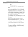
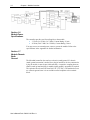
The module plugs into, and communicates with, a controller in the Micro800
family. The only exchange of data between the controller and the Plug-In Module
is through the API. The Plug-In Module shares the parallel bus with other plug-in
peripherals in the controller.
The block diagram for the plug-in module interface is shown below:

1-6 Chapter 1: Module Overview
User’s Manual Pub. 0300331-02 Rev. A
Section 1.6
Module Power
Specifications
The controller provides two Power Supplies to the module:
• 3.3 Volts (3.0 V Min, 3.6 V Max), Current Rating: 30 mA
• 24 Volts (20.4 V Min, 26.4 V Max), Current Rating: 30 mA
You may not use an external power source to power the module. Refer to the
specifications in the Appendix for further information.
Section 1.7
Module Chassis
Earth
Ground
The Micro800 controller does not have a chassis (earth) ground. If a chassis
(earth) ground connection is needed for a plug-in module or devices connected to
a plug-in module, it must be provided externally. A capacitive coupling between
chassis (earth) ground and plug-in module signal ground is acceptable if required.
The capacitor must be rated for least 500 VAC (707 VDC). The module does not
use a chassis ground since it is not available on the backplane or the terminal
block.

User’s Manual Pub. 0300331-02 Rev. A
Installation and Wiring
Section 2.1
Insert Module
into Controller
Follow the instructions to insert and secure the plug-in module to the controller.
WARNING
Electrostatic discharge can damage integrated circuits or semiconductors if
you touch bus connector pins. Follow these guidelines when you handle
the module:
• Touch a grounded object to discharge static potential.
• Wear an approved wrist-strap grounding device.
• Do not touch connectors or pins on component boards.
• Do not touch circuit components inside the module.
• If available, use a static-safe workstation.
• When not in use, keep the module in its static-shield box.
ATTENTION
Cet équipement est sensible aux décharges électrostatiques, lesquelles
peuvent entraîner des dommages internes et nuire à son bon
onctionnement.
Conformez-vous aux directives suivantes lorsque vous manipulez cet
équipement:
• Touchez un objet mis à la terre pour vous décharger de toute
électricité statique éventuelle.
• Portez au poignet un bracelet antistatique agréé.
• Ne touchez pas les connecteurs ni les broches figurant sur les
cartes des composants.
• Ne touchez pas les circuits internes de l’équipement.
• Utilisez si possible un poste de travail antistatique.
• Lorsque vous n’utilisez pas l’équipement, stockez-le dans un
emballage antistatique.

2-2 Chapter 2: Installation and Wiring
User’s Manual Pub. 0300331-02 Rev. A
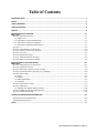
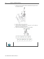
1. Position the plug-in module with the terminal block facing the front of
the controller as shown:
2. Snap the module into the module bay.
3. Using a screwdriver, tighten the 10…12 mm (0.39…0.47 in.) M3 self-
tapping screw to torque specifications.
4. Follow the wiring diagrams below to wire the module:
NOTE
IRET0 to IRET3 are reserved for a later date.

Chapter 2: Installation and Wiring 2-3
User’s Manual Pub. 0300331-02 Rev. A
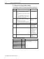
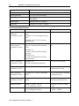
Section 2.2
Configuration
Tags
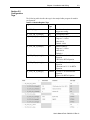
The following table describes the tags in the sample ladder program for module
configuration:
Table 2-1. Module Register Tags
Register
Data
Type
Comments
S1_CFG_Trigger INT Transition from 0 to non-zero to
trigger new config.
S1_CFG_CH_n_Parms[0] INT Configuration Bits
S1_CFG_CH_n_Parms[1] INT Maximum Range (default 19016)
Degrees C ×100 or
ohms div 10
Default: 19016
S1_CFG_CH_
n
_Parms[2]
INT
Minimum Range
Degrees C ×100 or
ohms div 10
Default: 0
S1_CFG_CH_n_String[0] STRING -COEFF-A for Steinhart-Hart
Equation
-BETA for BETA Equation
S1_CFG_CH_n_String[1] STRING -COEFF-B for Steinhart-Hart
Equation
-Resistance at 25 ºC for BETA
Equation
S1_CFG_CH_n_String[2]
STRING
-COEFF-C for Steinhart-Hart
Equation
Ignored for BETA Equation

2-4 Chapter 2: Installation and Wiring
User’s Manual Pub. 0300331-02 Rev. A
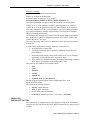
Section 2.3
New Config Trigger
(S1_CFG_Trigger)
This register is used as a trigger to the module that the configuration needs to be
applied. You first modify all of the configuration parameters, and then trigger the
new configuration.
To trigger, the register must first be set to zero for a minimum of 300 ms. A non-
zero value is then placed into the register to initiate the trigger. The non-zero
value should remain for a minimum of 300 ms before setting the register back to
zero. Only a transition from 0 to non-zero will cause a new configuration event.
These time delays are used to ensure the module has enough time to detect the
transition. It may be possible to trigger a new configuration below these
minimum values but this is not recommended.
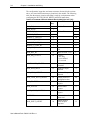
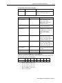
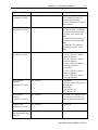
Section 2.4
Configuration Bits
(S1_CFG_CH_n_Parms[0])
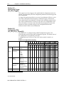
The 2080sc-NTC is configured using 8 SINT configuration registers. The
following table describes the module configuration registers. The default value of
the configuration is represented by zeroes (0).
A configuration error will be set if any of the values marked <unused> are
passed.
Table 2-2. Configuration Assembly
Bits 15 14 13 12 11 10 9 8 7 6 5 4 3 2 1 0
MSB
LSB
7 6 5 4 3 2 1 0 7 6 5 4 3 2 1 0
Ch0
Config.
2×
Bytes
Channel
Enable
Enable
Disable
0
1
Filter
Frequency
17 Hz
4 Hz
60 Hz
240 Hz
470 Hz
<unused>
0
0
0
0
1
1
0
0
1
1
0
×
0
1
0
1
0
×
Data
Format1
Engr. ×1
Engr. ×10
Raw/Proportional
<unused>
0
0
1
1
0
1
0
1
Linearization
Equation
Resistance
Steinhart-Hart
Raw Proportional
<unused>
0
0
1
1
0
1
0
1
Unused × × × × × × × ×
1 See Data Format.

Chapter 2: Installation and Wiring 2-5
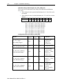
User’s Manual Pub. 0300331-02 Rev. A
Bits 15 14 13 12 11 10 9 8 7 6 5 4 3 2 1 0
MSB LSB
7 6 5 4 3 2 1 0 7 6 5 4 3 2 1 0
Ch1
Config.
2×
Bytes
Data structure the same as channel 0 above
Ch2
Config.
2×
Bytes
Data structure the same as channel 0 above
Ch3
Config.
2×
Bytes
Data structure the same as channel 0 above
Section 2.5
Data Format
2.5.1 EU×1
This displays the measured readings in their natural integer form. Due to the
measurement range and 16-bit data size, the highest resolution that can be
displayed for resistance is 10 ohms. Temperatures will have two decimal places
of resolution.
For resistance, it will be in the range from 0 to 32767 which represents resistance
in ohms divided by ten (0 to 327.67 kohms).
For temperature, it will display in the range from +32767 to -32768 (+327.67
degrees C to -327.68 degrees C). The displayed values are clipped at the user-
defined Maximum and Minimum parameters (defined below).
2.5.2 EU×10
This display format is the same as EU ×1 but divided by 10.
2.5.3 Raw Proportional
The Raw Proportional Data Format uses the Maximum and Minimum user-
defined values as its end points and scale relative to them. The Maximum Range
is represented by +32767 while the Minimum Range is -32768 to give a full 16-
bit span.
The output is scaled relative to those two user-defined values. When Equation is
set to Resistance, you enter appropriate resistance values for the Maximum and
Minimum parameters. For the other Equation settings, you enter appropriate
temperature values for the Maximum and Minimum parameters.
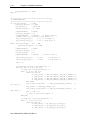
2.5.4 Equation
BETA
If the Equation is set to BETA, the COEFF-A/BETA string contains the BETA
parameter. The COEFF-B/R@25C string contains the resistance at 25 ˚C.

2-6 Chapter 2: Installation and Wiring
User’s Manual Pub. 0300331-02 Rev. A
COEFF-C string will be ignored.
Temperature in Kelvin is determined by the following formula:
1
=1
+1
ln
Where:
B = User-supplied BETA parameter
R0 = User-supplied resistance at room temperature (T0).
T0 = (constant) Room temperature (25˚ C) in Kelvin (298.15).
R = Measured resistance.
After solving for T, it is then converted to Celsius: T - 273.15
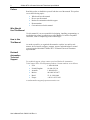
Steinhart-Hart
If the Equation is set to Steinhart-Hart, all three COEFF strings are used.
The module uses the following formula to determine temperature:
1
=+ln()+(ln())
Where:
A, B, C = Coefficients from thermistor specification.
R = Measured resistance
T = Temperature in Kelvin.
The final result is then converted to degrees Celsius: T - 273.15
The above formula images were copied from Wikipedia:
http://en.wikipedia.org/wiki/Thermistor
Resistance
If the Equation is set to Resistance, all COEFF strings are ignored and only the
actual measured resistance is displayed.
Maximum Range (S1_CFG_CH_n_Parms[1])
Minimum Range (S1_CFG_CH_n_Parms[2])
Since this module provides general purpose measurements, it is necessary to
know the maximum and minimum displayed values to allow for status processing
of over and under range as well as Raw Proportional. The thermistor type will
determine what the optimal displayed values are. The displayed reading will be
clipped to these values. By default, Maximum Range is set to 19016, Minimum
Range is set to 0.
The value is a signed, 16-bit integer. It represents temperature in degrees Celsius
multiplied by 100 when the Equation is not set to Resistance.
If the Equation is set to Resistance, the values represent ohms divided by 10.
The Maximum cannot be not be equal to, or less than, the Minimum. An invalid
configuration is set in that case.
This format allows for temperature spans from +327.67 C to -327.68 C. Setting
extreme values does not guarantee measurement within that range.
Negative Resistance values are not valid.
Temperature example:
Enter 8000 for 80.00 C as the Maximum.
Enter -2000 for -20.00 C as the Minimum.

Chapter 2: Installation and Wiring 2-7
User’s Manual Pub. 0300331-02 Rev. A
Resistance example:
Enter 10000 for 100 Kohms as the Maximum.
Enter 1 for 10 ohms as the Minimum.
Resistance spans are from 0 to 327,670 ohms.
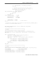
String Parameters (COEFF-A/BETA, COEFF-B/R@25C, C)
These string parameters are ignored when the Equation is set to Resistance.
COEFF-A serves as the parameter for BETA when Equation is set to BETA.
COEFF-B serves as the parameter for R@25C when Equation is set to BETA.
Due to the limitation of CCW, it is not possible to use a raw floating point data
type in the configuration. Instead, strings are used. The strings are in standard
IEEE 754 floating point format.
The Steinhart-Hart coefficients presented in the thermistor datasheet are entered
here. In the case of a BETA configured thermistor, only COEFF-A/BETA and
COEFF-B/R at 25 C are used.
The size of the string may be up to 16 characters. It is not necessary to terminate
with NULL.
A valid floating point number string is formed by a succession of:
• An optional plus or minus sign.
• A sequence of numeric digits, optionally containing a single decimal-
point character.
• An optional exponent part, which itself consists of an 'e' or 'E' character
followed by an optional sign and a sequence of digits.
• There shall be no characters following the floating point string (including
white space). All characters in the string must be valid.
The following are examples of acceptable entries:
• 1234
• -1234
• 1234.456
• -123.45
• 0.1234E-03
• -23.062E+12 (E or e may be used)
Invalid strings are rejected, and an invalid configuration bit is set in
MOD_STATUS register.
The following are invalid examples:
• a1234 Alpha character.
• 1234 Space after digit.
• 0 . 2 Space between characters.
• 0.123-E03 invalid expression. Correct entry is 0.123E-03
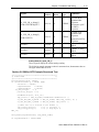
Section 2.6
Add the NTC to CCW
The 2080sc-NTC is configured for CCW (Connected Components Workbench)
using the PLUGIN_READ and PLUGIN_WRITE instructions for generic plug-in
modules.

2-8 Chapter 2: Installation and Wiring
User’s Manual Pub. 0300331-02 Rev. A
The configuration, input data, and status structures discussed in the sections
above, are stored at different memory locations in the module. The following
table lists the memory location offset that is used for each parameter when
configuring the PLUGIN_READ, WRITE, and INFO instructions.
Table 2-3. Parameter Offset for Module Block (0×00 [0] to 0×1F [31])
Parameter
Offset
(Dec)
Comments
Default
MOD_ID_LO 0 Module ID 195
MOD_ID_HI
1
0
VENDOR_ID_LO 2 Vendor ID 58
VENDOR_ID_HI
3
0
PRODUCT_TYPE_LO 4 10
PRODUCT_TYPE_HI 5 0
PRODUCT_CODE_LO 6 80
PRODUCT_CODE_HI 7 0
MOD_REV_LO 8 Minor revision, 1-
255
1
MOD_REV_HI
9
Major revision, 1-127
1
MOD_IRQ_STATUS 10 0: parity,
1: RA only,
2: user-defined,
3-7: reserved
0
CONTROLLER_STATUS
11
Read-only, written by
controller
0
MOD_NUM_INPUT 12 Number of Input
channels
4
MOD_NUM_OUTPUT 13 Number of Output
channels
0
MOD_CONF_DATA_OFFSET 14 Starting address of
configuration data
80
MOD_FEATURE 15 Module feature
register
32
MOD_STATUS
16
Module status
register
0
MODE_MODE_CONTROL 17 Module mode control
register
RESERVED 18 to 23 Returns value of zero
when read
MOD_INPUT_OFFSET 24
Starting address
offset of Input
Registers
32
La page est en cours de chargement...
La page est en cours de chargement...
La page est en cours de chargement...
La page est en cours de chargement...
La page est en cours de chargement...
La page est en cours de chargement...
La page est en cours de chargement...
La page est en cours de chargement...
La page est en cours de chargement...
La page est en cours de chargement...
La page est en cours de chargement...
La page est en cours de chargement...
La page est en cours de chargement...
La page est en cours de chargement...
La page est en cours de chargement...
La page est en cours de chargement...
La page est en cours de chargement...
La page est en cours de chargement...
-
 1
1
-
 2
2
-
 3
3
-
 4
4
-
 5
5
-
 6
6
-
 7
7
-
 8
8
-
 9
9
-
 10
10
-
 11
11
-
 12
12
-
 13
13
-
 14
14
-
 15
15
-
 16
16
-
 17
17
-
 18
18
-
 19
19
-
 20
20
-
 21
21
-
 22
22
-
 23
23
-
 24
24
-
 25
25
-
 26
26
-
 27
27
-
 28
28
-
 29
29
-
 30
30
-
 31
31
-
 32
32
-
 33
33
-
 34
34
-
 35
35
-
 36
36
-
 37
37
-
 38
38


Spectrum Controls 2080sc-NTC Le manuel du propriétaire
- Taper
- Le manuel du propriétaire
dans d''autres langues
Documents connexes
-
Spectrum Controls 2080sc-IF4U Le manuel du propriétaire
-
-
-
-
-
-