Spectrum Controls 2080sc-IF4U Le manuel du propriétaire
- Taper
- Le manuel du propriétaire

User’s Manual Pub. 0300255-02 Rev. A
Micro800TM 4-Channel
Universal Analog Module
Catalog Number: 2080sc-IF4U

ii 2080-IF4U 4-Channel Universal Analog Module
User’s Manual Pub. 0300255-02 Rev. A
Important Notes
1. Please read all the information in this owner’s guide before installing the
product.
2. The information in this owner's guide applies to hardware Series A and
firmware version 1.1 or later.
3. This guide assumes that the reader has a full working knowledge of the
relevant processor.
Notice
The products and services described in this owner's guide are useful in a wide
variety of applications. Therefore, the user and others responsible for applying
the products and services described herein are responsible for determining their
acceptability for each application. While efforts have been made to provide
accurate information within this owner's guide, Spectrum Controls, Inc. assumes
no responsibility for the accuracy, completeness, or usefulness of the information
herein.
Under no circumstances will Spectrum Controls, Inc. be responsible or liable for
any damages or losses, including indirect or consequential damages or losses,
arising out of either the use of any information within this owner's guide or the
use of any product or service referenced herein.
No patent liability is assumed by Spectrum Controls, Inc. with respect to the use
of any of the information, products, circuits, programming, or services referenced
herein.
The information in this owner's guide is subject to change without notice.
Limited Warranty
Spectrum Controls, Inc. warrants that its products are free from defects in
material and workmanship under normal use and service, as described in
Spectrum Controls, Inc. literature covering this product, for a period of 1 year.
The obligations of Spectrum Controls, Inc. under this warranty are limited to
replacing or repairing, at its option, at its factory or facility, any product which
shall, in the applicable period after shipment, be returned to the Spectrum
Controls, Inc. facility, transportation charges prepaid, and which after
examination is determined, to the satisfaction of Spectrum Controls, Inc., to be
thus defective.
This warranty shall not apply to any such equipment which shall have been
repaired or altered except by Spectrum Controls or which shall have been subject
to misuse, neglect, or accident. In no case shall the liability of Spectrum
Controls, Inc. exceed the purchase price. The aforementioned provisions do not
extend the original warranty period of any product which has either been repaired
or replaced by Spectrum Controls, Inc.

User’s Manual Pub. 0300255-02 Rev. A
Table of Contents
IMPORTANT NOTES ................................................................................................................................................. II
NOTICE ..................................................................................................................................................................... II
LIMITED WARRANTY ................................................................................................................................................ II
TABLE OF CONTENTS ............................................................................................................................................... III
PREFACE .................................................................................................................................................................. IV
MODULE OVERVIEW........................................................................................................................... 1-1
SECTION 1.1 GENERAL DESCRIPTION .......................................................................................................................... 1-1
SECTION 1.2 ENVIRONMENT AND ENCLOSURE .............................................................................................................. 1-2
SECTION 1.3 PREVENT ELECTROSTATIC DISCHARGE ....................................................................................................... 1-4
SECTION 1.4 PARTS LIST .......................................................................................................................................... 1-4
SECTION 1.5 HARDWARE FEATURES ........................................................................................................................... 1-5
SECTION 1.6 MODULE POWER SPECIFICATIONS ............................................................................................................ 1-6
SECTION 1.7 MODULE CHASSIS EARTH GROUND.......................................................................................................... 1-6
INSTALLATION AND WIRING .............................................................................................................. 2-1
SECTION 2.1 INSERT MODULE INTO CONTROLLER ......................................................................................................... 2-1
SECTION 2.2 CONFIGURING THE MODULE .................................................................................................................... 2-3
SECTION 2.3 MODULE INPUT DATA ............................................................................................................................ 2-5
SECTION 2.4 ADD THE IF4U TO CCW ......................................................................................................................... 2-7
SECTION 2.5 TECHNICAL ASSISTANCE ........................................................................................................................ 2-11
APPENDIX A CONFIGURATION INFORMATION ..................................................................................................... A-1
INDEX .................................................................................................................................................................... I-7

iv 2080-IF4U 4-Channel Universal Analog Module
User’s Manual Pub. 0300255-02 Rev. A
Preface
Read this preface to familiarize yourself with the rest of the manual. This preface
covers the following topics:
•Who should use this manual
•How to use this manual
•Rockwell Automation technical support
•Documentation
•Conventions used in this manual
Who Should
Use This Manual
Use this manual if you are responsible for designing, installing, programming, or
troubleshooting control systems that use Allen-Bradley I/O and/or compatible
controllers, such as CompactLogix and ControlLogix.
How to Use
This Manual
As much as possible, we organized this manual to explain, in a task-by-task
manner, how to install, configure, program, operate, and troubleshoot a control
system using the Micro800™ 2080sc-IF4U 4-Channel Universal Analog Module.
Rockwell
Automation
Technical
Support
For technical support, please contact your local Rockwell Automation
TechConnect Office for all Spectrum products. Contact numbers are as follows:
•USA 1-440-646-6900
•United Kingdom 01-908-635-230
•Australia 1-800-809-929
•Mexico 001-888-365-8677
•Brazil 55-11-3618-8800
•Europe +49-211-41553-630
or send an email to support@spectrumcontrols.com
Documentation
If you would like a .PDF version of a manual, you can download a free electronic
version at www.spectrumcontrols.com
Conventions
Used in This
Manual
The following conventions are used throughout this manual:
•Bulleted lists (like this one) provide information not procedural steps.
•Numbered lists provide sequential steps or hierarchical information.
•Italic type is used for emphasis.
•Bold type identifies headings and sub-headings:

2080-IF4U 4-Channel Universal Analog Module v
User’s Manual Pub. 0300255-02 Rev. A
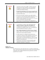
WARNING
Identifies information about practices or circumstances that can lead to
personal injury or death, property damage, or economic loss. Attentions
help you to identify a hazard, avoid a hazard, and recognize the
consequences.
ATTENTION
Actions ou situations risquant d’entraîner des blessures pouvant être
mortelles, des dégâts matériels ou des pertes financières. Les messages
« Attention » vous aident à identifier un danger, à éviter ce danger et en
discerner les conséquences.
NOTE
Identifies information that is critical for successful application and
understanding of the product.

vi 2080-IF4U 4-Channel Universal Analog Module
User’s Manual Pub. 0300255-02 Rev. A

User’s Manual Pub. 0300255-02 Rev. A
Module Overview
Section 1.1
General
Description
The 2080sc-IF4UV2 Universal Analog Input Module is a four-point universal
analog input module for use with Rockwell Automation Micro800™ systems.
This module measures analog inputs on up to four concurrent channels of
current, voltage and thermocouples and/or up to two channels of 4-wire RTD and
resistance measurements. The 2080sc-IF4UV2 module uses a 20-bit Sigma-Delta
analog-to-digital converter to achieve 16-bit resolution. All inputs have fault
tolerance and ESD protection to avoid damage to circuitry on the board.
The module plugs into any spare plug-in slot on the PLC. A 40-pin connector
provides the connection between the controller and the module. The module
interfaces with the controller via an Asynchronous Parallel Interface (API). The
module shares this parallel bus with other peripherals in the controller.
The exchange of data between the module and controller is used to communicate
module configuration, status and digitized samples from the four analog inputs.
Other types of exchanges also occur across the API. These exchanges include
reset commands by the controller, interrupts from the module to the controller,
module status queries by the controller, configuration changes and other
associated communications.
Power is provided across the backplane connector used to implement the API.
Analog input signals are connected to the module via a 12-pin terminal block on
the module.
The module provides the following functions:
• Use any combination of input types at one time.
• Is individually programmable for each channel.
• Is easy to configure using CCW programming software.
• Has channel-selectable filtering for fastest analog update time and noise
rejection.
• Has cold junction compensation included for thermocouples.
• Has accuracy comparable with dedicated analog modules.
• Provides 3-wire support for RTDs.
The I/O module operates in normal run mode when installed in a Micro800
controller chassis and is powered on. The I/O module is designed to operate 24
hours a day 7 days a week for a period of years with only periodic shutdowns for
maintenance.

1-2 Chapter 1: Module Overview
User’s Manual Pub. 0300255-02 Rev. A
The unit may be operated attended or unattended.
Section 1.2
Environment
and Enclosure
WARNING
This equipment is intended for use in a Pollution Degree 2 industrial
environment, in overvoltage Category II applications (as defined in IEC
publication 60664-1), at altitudes up to 2000 meters (6562 feet) without
derating.
This equipment is considered Group 1, Class A industrial equipment
according to IEC/CISPR Publication 11. Without appropriate precautions,
there may be potential difficulties ensuring electromagnetic compatibility
in other environments due to conducted as well as radiated disturbance.
This equipment is supplied as open-type equipment. It must be mounted
within an enclosure that is suitably designed for those specific
environmental conditions that will be present and appropriately designed
to prevent personal injury resulting from accessibility to live parts. The
enclosure must have suitable flame-retardant properties to prevent or
minimize the spread of flame, complying with a flame spread rating of 5
VA, V2, V1, V0 (or equivalent) if non-metallic. The interior of the
enclosure must be accessible only by the use of a tool. Subsequent
sections of this publication may contain additional information regarding
specific enclosure type ratings that are required to comply with certain
product safety certifications.
In addition to this publication, see:
• Industrial Automation Wiring and Grounding Guidelines, Allen-
Bradley publication 1770-4.1, for additional installation
requirements.
NEMA Standards publication 250 and IEC publication 60529, as
applicable, for explanations of the degrees of protection provided by
different types of enclosure.

Chapter 1: Module Overview 1-3
User’s Manual Pub. 0300255-02 Rev. A
WARNING
Cet équipement est prévu pour fonctionner en environnement industriel
avec une pollution de niveau 2, dans des applications de surtension de
catégorie II (telles que définies dans la publication 60664-1 de la CEI) et à
une altitude maximum de 2000 m sans déclassement.
Cet équipement est considéré comme étant un équipement industriel du
Groupe 1, classe A selon CEI/CISPR 11. En l’absence de précautions
appropriées, des problèmes de compatibilité électromagnétique peuvent
survenir dans des environnements résidentiels et dans d’autres
environnement en raison de perturbations conduites et rayonnées.
Cet équipement est fourni en tant qu’équipement de type « ouvert ». Il doit
être installé à l’intérieur d’une armoire fournissant une protection adaptée
aux conditions d’utilisation ambiantes et suffisante pour éviter toute
blessure pouvant résulter d’un contact direct avec des composants sous
tension.
L’armoire doit posséder des propriétés ignifuges capables d’empêcher ou
de limiter la propagation des flammes, correspondant à un indice de
propagation de 5VA, V2, V1, V0 (ou équivalent) dans le cas d’une armoire
non métallique.
L’accès à l’intérieur de l’armoire ne doit être possible qu’à l’aide d’un
outil. Cette armoire doit permettre des connexions d’alimentation par un
système de câblage de Classe I, Division 2, conformément au code
électrique national (NEC). Certaines sections de la présente publication
peuvent comporter des recommandations supplémentaires portant sur les
indices de protection spécifiques à respecter pour maintenir la conformité à
certaines normes de sécurité.
En plus de cette publication, consultez:
• La publication Rockwell Automation 1770-4.1, « Industrial
Automation Wiring and Grounding Guidelines », pour d’autres
critères d’installation.
• La publication 250 de la norme NEMA ou la publication 60529 de
la CEI, selon le cas, pour obtenir une description des indices de
protection que fournissent les différents types d’armoires.

1-4 Chapter 1: Module Overview
User’s Manual Pub. 0300255-02 Rev. A
Section 1.3
Prevent
Electrostatic
Discharge
WARNING
Electrostatic discharge can damage integrated circuits or semiconductors if
you touch bus connector pins. Follow these guidelines when you handle
the module:
• Touch a grounded object to discharge static potential.
• Wear an approved wrist-strap grounding device.
• Do not touch connectors or pins on component boards.
• Do not touch circuit components inside the module.
• If available, use a static-safe workstation.
When not in use, keep the module in its static-shield box.
WARNING
Cet équipement est sensible aux décharges électrostatiques, lesquelles
peuvent entraîner des dommages internes et nuire à son bon
onctionnement.
Conformez-vous aux directives suivantes lorsque vous manipulez cet
équipement:
• Touchez un objet mis à la terre pour vous décharger de toute
électricité statique éventuelle.
• Portez au poignet un bracelet antistatique agréé.
• Ne touchez pas les connecteurs ni les broches figurant sur les
cartes des composants.
• Ne touchez pas les circuits internes de l’équipement.
• Utilisez si possible un poste de travail antistatique.
Lorsque vous n’utilisez pas l’équipement, stockez-le dans un
emballage antistatique.
Section 1.4
Parts List
Your package contains one Micro800 Universal Analog Input Plug-in Module,
installation screws, and one Quick Start Guide.
You can choose to wire the plug-in before inserting it into the controller or wire
it once the module is secured in place.

Chapter 1: Module Overview 1-5
User’s Manual Pub. 0300255-02 Rev. A
WARNING
• This equipment is considered Group 1, Class A industrial
equipment according to IEC/CISPR 11. Without appropriate
precautions, there may be difficulties with electromagnetic
compatibility in residential and other environments due to
conducted and radiated disturbance.
• Be careful when stripping wires. Wire fragments that fall into the
controller could cause damage. Once wiring is complete, make
sure the controller is free of all metal fragments before removing
the protective debris strip.
• Do not wire more than 2 conductors on any single terminal.
• If you insert or remove the plug-in module while power is on, an
electrical arc can occur. This could cause an explosion in
hazardous location installations. Be sure that power is removed or
the area is nonhazardous before proceeding.
• Do not insert or remove the plug-in module while power is
applied; otherwise, permanent damage to equipment may occur.
WARNING
• Cet équipement est considéré comme étant un équipement
industriel du Groupe 1, classe A selon CEI/CISPR 11. En
l’absence de precautions appropriées, des problèmes de
compatibilité électromagnétique peuvent survenir dans des
environnements résidentiels et dans d’autres environnements en
raison de perturbations conduites et rayonnées.
• Soyez vigilant en dénudant les fils. Tout fragment de fil tombé
dans l’automate risquerait de le détériorer. Une fois le câblage
terminé, veillez à ce que l’automate ne présente aucun copeau de
métal avant de retirer la bande de protection.
• Ne câblez pas plus de 2 conducteurs sur une même borne.
• L’insertion ou le retrait du module enfichable sous tension peut
provoquer un arc électrique, susceptible de provoquer une
explosion dans un environnement dangereux. Assurez-vous que
l’alimentation est coupée ou que l’environnement est classé non
dangereux avant de poursuivre.
• N’insérez pas et ne retirez pas le module enfichable quand
l’équipement est sous tension, au risque de provoquer des
dommages irrémédiables à l’équipement.
Section 1.5
Hardware Features
The module plugs into, and communicates with, a controller in the Micro800
family. The only exchange of data between the controller and the Plug-In Module
is through the API. The Plug-In Module shares the parallel bus with other
peripherals in the controller.

1-6 Chapter 1: Module Overview
User’s Manual Pub. 0300255-02 Rev. A
The block diagram for the Plug-In Module interface is shown below:
Section 1.6
Module Power
Specifications
The controller provides two Power Supplies to the module:
• 3.3 Volts (3.0 V Min, 3.6 V Max), Current Rating: 30 mA
• 24 Volts (20.4 V Min, 26.4 V Max), Current Rating: 30 mA
You may not use an external power source to power the module. Refer to the
specifications in the Appendix for further information.
Section 1.7
Module Chassis
Earth
Ground
The Micro800 controller does not have a chassis (earth) ground. If a chassis
(earth) ground connection is needed for a Plug-In Module or devices connected
to a Plug-In Module, it must be provided externally. A capacitive coupling
between chassis (earth) ground and Plug-In module signal ground is acceptable if
required. The capacitor must be rated for least 500 VAC (707 VDC). The
IF4UV2 module does not use a chassis ground since it is not available on the
backplane or the terminal block.

User’s Manual Pub. 0300255-02 Rev. A
Installation and Wiring
Section 2.1
Insert Module
into Controller
Follow the instructions to insert and secure the plug-in module to the controller.
WARNING
Electrostatic discharge can damage integrated circuits or semiconductors if
you touch bus connector pins. Follow these guidelines when you handle
the module:
• Touch a grounded object to discharge static potential.
• Wear an approved wrist-strap grounding device.
• Do not touch connectors or pins on component boards.
• Do not touch circuit components inside the module.
• If available, use a static-safe workstation.
• When not in use, keep the module in its static-shield box.
WARNING
Cet équipement est sensible aux décharges électrostatiques, lesquelles
peuvent entraîner des dommages internes et nuire à son bon
onctionnement.
Conformez-vous aux directives suivantes lorsque vous manipulez cet
équipement:
• Touchez un objet mis à la terre pour vous décharger de toute
électricité statique éventuelle.
• Portez au poignet un bracelet antistatique agréé.
• Ne touchez pas les connecteurs ni les broches figurant sur les
cartes des composants.
• Ne touchez pas les circuits internes de l’équipement.
• Utilisez si possible un poste de travail antistatique.
• Lorsque vous n’utilisez pas l’équipement, stockez-le dans un
emballage antistatique.

2-2 Chapter 2: Installation and Wiring
User’s Manual Pub. 0300255-02 Rev. A
4. Position the plug-in module with the terminal block facing the front of
the controller as shown:
5. Snap the module into the module bay.
6. Using a screwdriver, tighten the supplied, self-tapping screw to torque
specifications.
7. Follow the wiring diagrams below to wire the module:

Chapter 2: Installation and Wiring 2-3
User’s Manual Pub. 0300255-02 Rev. A
Section 2.2
Configuring
the Module
The 2080sc-IF4U is configured using 8 SINT configuration registers. The
following table describes the module configuration registers:
Bits 15 14 13 12 11 10 9 8 7 6 5 4 3 2 1 0
MSB
LSB
7 6 5 4 3 2 1 0 7 6 5 4 3 2 1 0
Ch0
Config.
2× Bytes
Channel
Enable
Enable
Disable
0
1
Filter
Frequency
17 Hz
4 Hz
60 Hz
240 Hz
470 Hz
0
0
0
0
1
0
0
1
1
0
0
1
0
1
0
Input Type 4-20 mA 0 0 0 0
0-20 mA 0 0 0 1
±10 V 0 0 1 0
0-10 V 0 0 1 1
0-5 V 0 1 0 0
±100 mV 0 1 0 1
±50 mV 0 1 1 0
Type J
TC
0 1 1 1
Type K
TC
1 0 0 0
Type T
TC
1 0 0 1
Type E
TC
1 0 1 0
100 Pt
385
1 0 1 1
1000 Pt
385
1 1 0 0
100 Pt
3916
1 1 0 1
1000 Pt
3916
1 1 1 0
0-3000
Ohms
1 1 1 1
Type R
TC1
1 0 0 0 0
Undefined
Bits
× ×

2-4 Chapter 2: Installation and Wiring
User’s Manual Pub. 0300255-02 Rev. A
Bits 15 14 13 12 11 10 9 8 7 6 5 4 3 2 1 0
MSB LSB
7 6 5 4 3 2 1 0 7 6 5 4 3 2 1 0
Data
Format1
Engr. ×1
Engr. ×10
0
0
0
1
Temp.
Units
Degrees C
Degrees F
0
1
2/3/4 Wire
RTD,
ignored for
R ranges.
3-Wire
(Default)
4-wire
with lead
2-wire
0
0
1
0
1
0
CJC Enable Enable
Disable
0
1
Ch1
Config.
2× Bytes
Data structure the same as channel 0 above
Ch2
Config.
2× Bytes
Data structure the same as channel 0 above
Ch3
Config.
2× Bytes
Data structure the same as channel 0 above
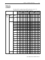
Table 2-2. Data Format
Input Type Input Value Condition EU ×1 EU ×10
E Thermocouple
1000.00 °C
High Range
10000
1000
-270.00 °C Low Range -2700 -270
J Thermocouple
1200.00 °C
High Range
12000
1200
-210.00 °C Low Range -2100 -210
K Thermocouple 1370.00 °C High Range 13700 1370
-270.00 °C Low Range -2700 -270
T Thermocouple 400.00 °C High Range 4000 400
-270.00 °C Low Range -2700 -270
R Thermocouple 1768.00 °C High Range 17680 1768
0.00 °C
Low Range
0
0
100 Ω Pt 0.385 850.00 °C High Range 8500 850
1 Type R thermocouple is only available on modules running firmware version 1.3 or higher. See Table 2-2. Data
Format.

Chapter 2: Installation and Wiring 2-5
User’s Manual Pub. 0300255-02 Rev. A
Input Type Input Value Condition EU ×1 EU ×10
-200.00 °C
Low Range
-2000
-200
1000 Ω Pt 0.385 850.00 °C High Range 8500 850
-200.00 °C
Low Range
-2000
-200
100 Ω Pt 0.392 630.00 °C High Range 6300 630
-200.00 °C
Low Range
-2000
-200
1000 Ω Pt 0.392 630.00 °C High Range 6300 630
-200.00 °C Low Range -2000 -200
0..3000 Ω 3000.00 ohms High Range 30000 3000
0.00 ohms Low Range 0 0
±
50 mV
50.00 mVDC
High Range
5000
500
-50.00 mVDC Low Range -5000 -500
±100 mV 100.00 mVDC High Range 10000 1000
-100.00 mVDC Low Range -10000 -1000
0..5 V
5.00 VDC
High Range
5000
500
0.00 VDC Low Range 0 0
±
10 V
10.00 VDC
High Range
10000
1000
-10.00 VDC Low Range -10000 -1000
0..10 V 10.00 VDC High Range 10000 1000
0.00 VDC Low Range 0 0
4..20 mA 20.00 mA High Range 20000 2000
4.00 mA
Low Range
4000
400
0..20 mA 20.00 mA High Range 20000 2000
0.00 mA
Low Range
0
0
CJC 85.00 °C High Range 850 85
-25.00 °C
Low Range
-250
-25
Section 2.3
Module Input Data
There are four input registers used to report data values for each of the four
channels and one register to report CJC sensor temperature.
Table 2-3. Module Input Data
Bit
15
14
13
12
11
10
9
8
7
6
5
4
3
2
1
0
Ch0 Channel 0 Input Data
Ch1
Channel 1 Input Data
Ch2 Channel 2 Input Data
Ch3 Channel 3 Input Data

2-6 Chapter 2: Installation and Wiring
User’s Manual Pub. 0300255-02 Rev. A
Bit 15
14
13
12
11
10
9
8
7
6
5
4
3
2
1
0
CJC
CJC Temperature in degrees C
There are four input registers used to report data values for each of the four
channels and one register to report CJC sensor temperature.
Table 2-4. Open-Circuit Status
Bit 7 6 5 4 3 2 1 0
NU
NU
O_CJC
U_CJC
OC3
OC2
OC1
OC0
Bit 0 for channel 0 open wire.
Bit 1 for channel 1 open wire.
Bit 2 for channel 2 open wire.
Bit 3 for channel 3 open wire.
Bit 4 is for CJC under range indication.
Bit 5 is for CJC over range indication.
Bit 6 and Bit 7 are not used.
Table 2-5. Under/Over Range Status
Bit 7 6 5 4 3 2 1 0
O3
O2
O1
O0
U3
U2
U1
U0
Bit 0 is for channel 0 under range indication.
Bit 1 is for channel 1 under range indication.
Bit 2 is for channel 2 under range indication.
Bit 3 is for channel 3 under range indication.
Bit 4 is for channel 0 over range indication.
Bit 5 is for channel 1 over range indication.
Bit 6 is for channel 2 over range indication.
Bit 7 is for channel 3 over range indication.
Table 2-6. General Module Status
Bit Number
Description
Notes
0-1
These 2 bits define module
operation mode,
0: Idle: Module is ready to RUN,
and I/O is off.
1: RUN: Module is under RUN,
and I/O is on.
2: Error: Error happens, and I/O
is off.
3: Busy: Module is busy, cannot
go to RUN, and I/O is off.
2
This bit defines module user
interrupt mode,
0: User Interrupt is disabled.
1: User Interrupt is enabled.
The IF4U does not
support this
functionality; this bit
is always off (0).

Chapter 2: Installation and Wiring 2-7
User’s Manual Pub. 0300255-02 Rev. A
Bit Number Description Notes
3
Reserved
4 SW Error Trigger condition –
Watchdog timer
triggered.
5 ADC Error Trigger condition –
ADC
communication
stops or ADC has
not sampled data for
long period of time.
6 Calibration Error Trigger condition –
blank calibration or
calibration
checksum error.
7 Configuration Error Wrong bits set in
channel
configuration.
Section 2.4
Add the IF4U to CCW
The 2080sc-IF4U is configured for CCW (Connected Components Workbench)
using the PLUGIN_READ and PLUGIN_WRITE instructions for generic plug-in
modules.
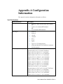
The configuration, input data, and status structures discussed in the sections
above, are stored at different memory locations in the module. The following
table lists the memory location offset for each parameter which is used when
configuring the PLUGIN_READ, WRITE, and INFO instructions.
Table 2-7. Parameter Offset
Parameter Offset (Dec) Comments
MOD_ID_LO 0 Module ID
MOD_ID_HI
1
VENDOR_ID_LO 2 Vendor ID
VENDOR_ID_HI
3
PRODUCT_TYPE_LO 4
PRODUCT_TYPE_HI 5
PRODUCT_CODE_LO 6
PRODUCT_CODE_HI 7
MOD_REV_LO
8
Minor revision, 1-255
MOD_REV_HI 9 Major revision, 1-127
MOD_STATUS
16
Module status register
(see Table 6)

2-8 Chapter 2: Installation and Wiring
User’s Manual Pub. 0300255-02 Rev. A
Parameter Offset (Dec) Comments
SYNC_DATA_LATCH
26
Writing 0×A5 to this register
triggers input data latch
CONFIG_IN0_LO
32
Channel Configuration
Registers
CONFIG_IN0_HI 33
CONFIG_IN1_LO 34
CONFIG_IN1_HI
35
CONFIG_IN2_LO 36
CONFIG_IN2_HI
37
CONFIG_IN3_LO 38
CONFIG_IN3_HI
39
INPUT_DATA_0_LO 48 Input Data
(Format is 16-bit signed
integer)
INPUT_DATA_0_HI
49
INPUT_DATA_1_LO 50
INPUT_DATA_1_HI
51
INPUT_DATA_2_LO 52
INPUT_DATA_2_HI
53
INPUT_DATA_3_LO 54
INPUT_DATA_3_HI
55
CJC_DATA_LO 56
CJC_DATA_HI 57
OC_STATUS 80 Open-circuit status
U_O_RANGE_STATUS 81 Under/over range status
The following sample program, written in structured text, demonstrates how to
configure the module in CCW:
u800Slot := 3; (* Slot number 3 for IF4U module. *)
ConfigArray[1] := 112; (*Ch0 Config LSB 112d for Type J TC *)
ConfigArray[2] := 0; (*Ch0 Config MSB *)
ConfigArray[3] := 16; (*Ch1 Config LSB 16d for 0-20mA *)
ConfigArray[4] := 0; (*Ch1 Config MSB *)
ConfigArray[5] := 48; (*Ch2 Config LSB 48d for 0-10Vdc *)
ConfigArray[6] := 0; (*Ch2 Config MSB *)
ConfigArray[7] := 240; (*Ch3 Config LSB =240d for 0-3000 ohm X10
*)
ConfigArray[8] := 0; (*Ch3 Config MSB =0d for resistance *)
WriteConfig(true,u800Slot,32,8,ConfigArray); (* Write
the config. data to the module*)
ReadModStatus(true,u800Slot,16,1,IF4U_Slot3_ModStatus); (* Read
La page est en cours de chargement...
La page est en cours de chargement...
La page est en cours de chargement...
La page est en cours de chargement...
La page est en cours de chargement...
La page est en cours de chargement...
La page est en cours de chargement...
La page est en cours de chargement...
La page est en cours de chargement...
La page est en cours de chargement...
La page est en cours de chargement...
La page est en cours de chargement...
La page est en cours de chargement...
La page est en cours de chargement...
-
 1
1
-
 2
2
-
 3
3
-
 4
4
-
 5
5
-
 6
6
-
 7
7
-
 8
8
-
 9
9
-
 10
10
-
 11
11
-
 12
12
-
 13
13
-
 14
14
-
 15
15
-
 16
16
-
 17
17
-
 18
18
-
 19
19
-
 20
20
-
 21
21
-
 22
22
-
 23
23
-
 24
24
-
 25
25
-
 26
26
-
 27
27
-
 28
28
-
 29
29
-
 30
30
-
 31
31
-
 32
32
-
 33
33
-
 34
34


Spectrum Controls 2080sc-IF4U Le manuel du propriétaire
- Taper
- Le manuel du propriétaire
dans d''autres langues
Documents connexes
-
Spectrum Controls 2080sc-OW2IHC Le manuel du propriétaire
-
-
-
-
-
-
-
-