
Quick start guide for
Digital, Dual Digital
& Analogue Displays
English Français Deutsch Nederlands Espagñol Italiano

Quick start guide for Digital, Dual Digital & Analogue Displays
www.raymarine.com
Notice:
For full user documentation for the Micronet family and for other useful
infomation please refer to the CD-ROM supplied with your product, or to
the Raymarine website at www.raymarine.com.
Note:
Pour la documentation complète d'utilisation de la famille Micronet et pour
toute autre information utile, veuillez consulter le CD-Rom qui est fourni
avec votre produit ou bien consulter le site internet de Raymarine
www.raymarine.com
Hinweis:
Die komplette Dokumentation der Micronet-Familie und weitere nützliche
Informationen finden Sie auf der dem Produkt beiliegenden CD-ROM oder
auf der Internetseite www.raymarine.com
Opmerking:
Kijk voor de volledige informatie over de Micronet instrumenten familie op
de CD-ROM die bij uw product zit of op de website www.raymarine.com.
Nota:
Para documentación completa sobre la gama Micronet y otro tipo de
información útil, por favor consulte el CD-ROM suministrado con su
producto o visite la página web de Raymarine en www.raymarine.com.
Nota:
Per la documentazione completa sulla famiglia Micronet e altre
informazioni fare riferimento al CD-ROM fornito con il prodotto o al sito
Raymarine: www.raymarine.com

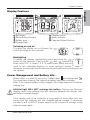
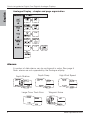
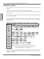
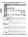
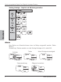
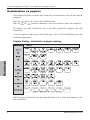
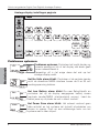
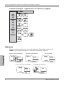
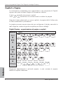
Display Features
1
www.raymarine.com
English
Display Features
Switching on and off
To switch the display on or off,press the
button and hold for two seconds
Backlighting
To adjust the display backlighting press and hold the
button for two seconds. Then use the and buttons to
select from OFF, or levels 1,2,3. To save power, setup can be
used to set individual displays to local backlight control;
otherwise the backlight function will set the backlight level for all displays on
the network.
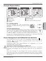
Power Management and Battery Life
Power status is shown by two icons : battery level and charge rate .
The more bars showing, the higher the battery level/rate of charge.
Note: If the internal battery is fully charged, the charge rate icon will always
indicate low.
Artificial light WILL NOT recharge the battery. Placing your Micronet
display close to an artificial light will seriously damage the display. Only
recharge in natural daylight.
If the displays are to be stored for a long period of time before next use
ensure that the batteries are fully charged before storage. If necessary
connect to a 9 to 30V DC power supply for 24 hrs prior to storage, using
external power leads.
Set Button
Setup Button Prompts
Battery level
Charge Rate
7
5
3
1
Chapter Button
Alarm Indicator
Page and Adjust Buttons
6
4
2

English
Quick start guide for Digital, Dual Digital & Analogue Displays
2www.raymarine.com
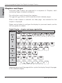
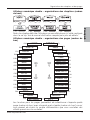
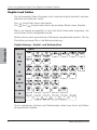
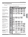
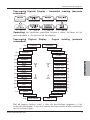
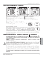
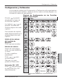
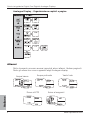
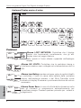
Chapters and Pages
Instrument Data screens are organised in a sequence of Chapters, each
containing Pages of related information.
The button scrolls through the chapters.
The and buttons scroll forward and back between pages.
When a new chapter is selected, the data page last selected for that
chapter is displayed
Pages can be hidden to configure the displays to your exact needs, see the
full user guides for details.
Digital Display - chapter and page organisation
Repeated pressing of the page buttons cycles the display through the pages
of the selected chapter.

Chapters and Pages
3
www.raymarine.com
English
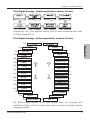
Dual Digital Display - chapter organisation (upper window)
Note: The user defined chapter is only displayed if it has been configured in
setup, see the full user guide for details
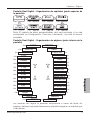
Dual Digital Display - page organisation (lower window)
The page buttons cycle the lower pane through all the available data pages
in turn, i.e any data page can be displayed together with any chapter.
TIME
SPEED P1
VMG P2
VMG WP P3
LOG P4
TRIP P
5
MAX SPD P
6
AVG SPD P
7
DEPTH P
8
MIN DEPTH P
9
MAX DEPTH P1
A SPDWIND P1
A ANG
WIND
P1
2
TRU SPD
WIND
P1
3
TRU ANG
WIND
P1
4
MAG TWDIR P15
BEAUF P16
LIFT P17
MAG HDG
P18
TACK
P19
SOG
P20
COG
P21
LAT
P22
LON
P23
BTW
P24
DTW
P25
XTE
P26
TTG
P27
SEA
P28
TIMER
P29
P30
DATE
P31
LOCK
P33
VOLTS
P32

Quick start guide for Digital, Dual Digital & Analogue Displays
4www.raymarine.com
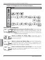
English
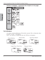
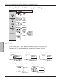
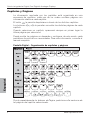
Analogue Display - chapter and page organisation
Alarms
A number of data alarms can be configured in setup. See page 5
Note: alarms are not supported by the Analogue display.
Depth Shallow Depth Deep High Wind Speed
Large Cross Track Error Waypoint Arrive

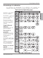
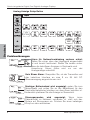
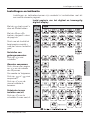
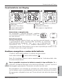
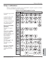
Setup and Calibration
5
www.raymarine.com
English
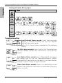
Setup and Calibration
Setup and Calibration displays are arranged in Chapters, each containing
a number of related Pages.
The button scrolls
through the Chapters.
The and
buttons scroll forward
and back between
pages.
Scroll to the chapter
heading page before
changing chapter
Resetting memory
values:
Press to reset.
Editing Values:
Within a page,press
to change a
setting.
The setting will flash.
Press or to
adjust the setting.
Press to save the
new setting
TogglingON/OFF
selections:
Press to toggle
between ON and OFF
Digital and Dual Digital Setup pages

Quick start guide for Digital, Dual Digital & Analogue Displays
6www.raymarine.com
English
Analogue Display Setup pages
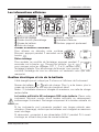
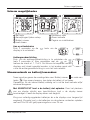
Troubleshooting
Lost Network Alarm sounds: check that the master
display is working correctly and that the affected
display(s) are within range.
Note: this is the only alarm supported by the analogue
display
No Volts alarm sounds: check that the Hull Transmitter and
Wireless (NMEA) interface are connected to a 9 to 30V DC
supply.
Low Battery Alarm sounds: go to Setup/Health and check
the battery level for the Hull Transmitter/Wireless (NMEA)
Interface/Wind Transmitter as indicated by the alarm display.
Charge or place in bright sunlight if required.
Power Save Alarm sounds: there is no data activity on the
network, the system will close down to save power. Press any
button to cancel.

Les informations affichées
1
www.raymarine.com
Français
Les informations affichées
Allumer et éteindre l'instrument
Pour allumer ou éteindre votre système
Micronet, appuyez pendant 2 secondes sur le
bouton
Rétro éclairage
Pour accéder au contrôle de l'éclairage, appuyez pendant 2
secondes sur la touche . Pressez les boutons et
pour naviguer entre les réglages OFF, 1, 2 et 3, pendant que
l'éclairage s'adapte. Pour économiser de l'énergie, vous pouvez
contrôler l'éclairage de tous les afficheurs ou seulement celui que vous
manipulez.
Gestion électrique et vie de la batterie
L'état énergétique est indiqué par 2 icônes sur l'afficheur de l'instrument:
Niveau de batterie et ratio de charge. Plus il y a de barres, plus le
niveau de la batterie ou son ratio de charge est élevé
Notez : Si la batterie interne est chargée au maximum, son ratio de charge
restera faible.
La lumière artificielle NE rechargera PAS votre batterie. Placer votre
instrument Micronet proche d'une lumière artificielle va sérieusement
endommager l'instrument. Recharger uniquement à la lumière naturelle du
jour.
Si les instruments sont conservés pendant une longue période sans
utilisation (Hivernage), vérifiez que les batteries sont chargées au maximum
avant stockage.
Si nécessaire, connectez à une alimentation 9-30 V pendant 24 h avant
stockage, en utilisant des prises de courant externes.
Bouton de réglage
Guides bouton paramétrage
Niveau de batterie
Ratio de charge
7
5
3
1
Bouton chapitre
Indicateur d’alarme
Boutons pages et ajustement
6
4
2

Quick start guide for Digital, Dual Digital & Analogue Displays
2www.raymarine.com
Français
Chapitres et pages
Les informations fournies par l'instrument sont organisées en "Chapitres et
Pages".
Utilisez la touche pour naviguer entres les chapitres.
Utilisez les touches et pour se déplacer entre les pages au sein
d'un chapitre
Une fois qu'un nouveau chapitre a été sélectionné, la dernière page utilisée
du chapitre apparaît.
Les pages peuvent être cachées pour vous permettre de configurer vos
afficheurs à vos propres besoins - Voir le manuel d'utilisation complet pour
plus de détails.
Afficheur numérique -organisation des chapitres et des pages
La sélection des chapitres et des pages est cyclique, et vous passez d'une
page à une autre du chapitre sélectionné en appuyant plusieurs fois sur les
boutons des pages.

Organisation des chapitres et des pages
3
www.raymarine.com
Français
Afficheur numérique double - organisations des chapitres (cadran
du haut)
Note :Le chapitre défini de l'utilisateur ne sera affiché que si il a été configuré
dans le set up- Voir le manuel d'utilisation complet pour plus de détails.
Afficheur numérique double - organisations des pages (cadran du
bas)
Les touches pour les pages permettent de sélectionner n'importe quelle
page (cadran du bas) avec n'importe quel chapitre (cadran du haut) ce qui
vous permet de choisir le couple d'informations que vous souhaitez voir
affiché quand vous le souhaitez.
TIME
SPEED P1
VMG P2
VMG WP P3
LOG P4
TRIP P5
MAX SPD P6
AVG SPD P7
DEPTH P8
MIN DEPTH P9
MAX DEPTH P1
0
A SPDWIND P11
A ANG
WIND
P12
TRU SPD
WIND
P13
TRU ANG
WIND
P14
MAG TWDIR P15
BEAUF P16
LIFT P17
MAG HDG
P18
TACK
P19
SOG
P20
COG
P21
LAT
P22
LON
P23
BTW
P24
DTW
P25
XTE
P26
TTG
P27
SEA
P28
TIMER
P29
P30
DATE
P31
LOCK
P33
VOLTS
P32

Quick start guide for Digital, Dual Digital & Analogue Displays
4www.raymarine.com
Français
Afficheur analogique - organisation des chapitres et des pages
Les alarmes
Un certain nombre d'alarmes d'information peuvent être configurées dans
le menu " set up ". Voir page 5
Note : les alarmes ne dépendent pas de l'afficheur analogique
Depth Shallow Depth Deep High Wind Speed
Large Cross Track Error Waypoint Arrive

Paramétrage et calibration
5
www.raymarine.com
Français
Paramétrage et calibration
Les afficheurs de paramétrage et de calibration sont organisés en
chapitres, dont chacun contient un nombre de pages lui correspondant.
Le bouton navigue
entre les chapitres.
Les boutons et
avancent et reculent
entre les pages.
Passez à la page
principale du chapitre
avant de changer de
chapitre.
Chapitre Mémoire
(Memory)
Pressez la touche
pour re-initialiser.
Pour ajuster un
paramètre
A l'intérieur d'une page,
pressez la touche .
Le paramètre va
clignoter.
les touches et
permettent de modifier la
valeur.
Pressez la touche
pour sauvegarder le
nouveau paramètre.
Boutons de sélection
ON/OFF
Pressez la touche
pour passer de ON à
OFF.
Digital and Dual Digital Setup pages

Quick start guide for Digital, Dual Digital & Analogue Displays
6www.raymarine.com
Français
Pages paramétrage de l'afficheur analogique
Détection des anomalies
Signal d'alarme sonore de perte de réseau: Vérifiez
que le " Master* " fonctionne correctement et que l'(s)
afficheur(s) affecté n'est pas éloigné de sa plage de
fonctionnement.
Note: c'est la seule alarme qui dépend de l'afficheur
analogique
Signal d'alarme absence de tension: vérifiez que l'émetteur
de coque et l'interface NMEA soient connectés à une
alimentation entre 9 et 30 V.
Signal d'alarme batterie basse: passez en mode
paramétrage/ chapitre " HEALTH " et vérifiez le niveau de
charge sur le transmetteur de coque, l'interface NMEA, ou la
girouette anémomètre, comme il est indiqué sur l'afficheur de
l'alarme. Rechargez la batterie ou exposez aux rayons du soleil
si nécessaire.
Signal d'alarme d'économie d'énergie: tIl n'y a pas de
transfert de données au travers du réseau. Le signal sonore
indique que les instruments vont s'éteindre tout seuls. Pour
maintenir la centrale allumée, appuyez sur un bouton pour
annuler l'alarme

Anzeigen-Eigenschaften
1
www.raymarine.com
Deutsch
Anzeigen-Eigenschaften
Ein- und Ausschalten
Um die Anzeigen ein- oder auszuschalten
betätigen und halten Sie die Knopf für zwei
Sekunden.
Hintergrundbeleuchtung
Um die Hintergrundbeleuchtung einzuschalten drücken und
halten sie die Taste für zwei Sekunden. Dann benutzen sie
die und Tasten um Aus, oder den Beleuchtungsgrad 1,
2 oder 3 zu wählen. Um Strom zu sparen stellen Sie bei jeder
Anzeige die Hintergrundbeleuchtung individuell ein. Ansonsten wird die
Beleuchtung für das gesamte System übernommen.
Power Management und Haltbarkeit der Batterien
Der Stromstatus wird von zwei Icons angezeigt: Batterielevel und
Laderate. . Je mehr Balken angezeigt werden, desto höher ist der
Ladestatus der Batterie.
Anmerkung: Wenn die interne Batterie voll aufgeladen ist, ist die
Laderateanzeige immer niedrig.
Künstliches Licht lädt die Batterien NICHT auf.
Wenn Sie Ihre Micronet-Anzeige nahe einer künstlichen Lichtquelle
platzieren beschädigen Sie Ihre Anzeige. Laden Sie nur mit natürlichem
Licht
Wenn die Anzeigen für eine längere Zeit verpackt aufbewahrt werden,
stellen Sie sicher, dass sie komplett aufgeladen sind. Wenn nötig schließen
Sie die Anzeigen an eine externe 9 bis 30 Volt DC Stromversorgung für 24
Stunden an.
Set-Knopf
Setup-Knopf
Batteriestatus
Laderate
7
5
3
1
Kapitelauswahl
Alarmindikator
Seiten und Einstellungs-Knopf
6
4
2

Quick start guide for Digital, Dual Digital & Analogue Displays
2www.raymarine.com
Deutsch
Kapitel und Seiten
Die Instrumenten Daten Anzeigen sind in mehrere Kapitel unterteilt, welches
mehrere Informationen bietet.
Der Knopf führt durch die Kapitel.
Die und Knöpfe leitet durch die einzelnen Seiten eines Kapitels
Wenn ein Kapitel ausgewählt ist wird die letzte Datenseite angezeigt, die
beim letzten Aufruf ausgewählt wurde.
Seiten können nach persönlichem Gebrauch ausgeblendet werden. Für die
Einstellung schauen Sie in die Betriebsanleitung.
Digital-Anzeige - Kapitel- und Seitenaufbau
Durch mehrfaches drücken der Seitenknöpfe rotiert man durch die Seiten
des gewählten Kapitels.

Kapitel- und Seitenaufbau
3
www.raymarine.com
Deutsch
Dual-Digital-Anzeige - Kapitelorganisation (oberes Fenster)
Anmerkung: Das "User defined" Kapitel wird nur dann angezeigt wenn dies
im Setup eingestellt ist.
Dual-Digital-Anzeige - Seitenorganisation (unteres Fenster)
Die Seitenknöpfe kreisen durch das untere Menü zur Anzeige aller
erhältlichen Daten, z.B. kann jede Datenseite zusammen mit jedem Kapitel
angezeigt werden.
TIME
SPEED P1
VMG P2
VMG WP P3
LOG P4
TRIP P5
MAX SPD P6
AVG SPD P7
DEPTH P8
MIN DEPTH P9
MAX DEPTH P10
A SPDWIND P11
A ANG
WIND
P12
TRU SPD
WIND
P13
TRU ANG
WIND
P14
MAG TWDIR P15
BEAUF P16
LIFT P17
MAG HDG
P18
TACK
P19
SOG
P20
COG
P21
LAT
P22
LON
P23
BTW
P24
DTW
P25
XTE
P26
TTG
P27
SEA
P28
TIMER
P29
P30
DATE
P31
LOCK
P33
VOLTS
P32

Quick start guide for Digital, Dual Digital & Analogue Displays
4www.raymarine.com
Deutsch
Untiefen Tiefen Hohe Windgeschwindigkeit
Querversetzung Waypoint erreichen
Analog-Anzeige - Kapitel und Seitenorganisation
Alarm
Eine Reihe von Alarmfunktionen kann im Setup eingestellt werden. Siehe
Seite 5.
Anmerkung: Alarme werden von der Analog-Anzeige nicht unterstützt.

Setup und Kalibrierung
5
www.raymarine.com
Deutsch
Setup und Kalibrierung
Setup und Kalibrierung sind in Kapitel unterteilt. Jedes beinhaltet eine Reihe
von Seiten.
Der Knopf scrollt
durch die Kapitel.
Die und
Knöpfe scrollen vor-
und rückwärts durch
die Seiten.
Scrollen Sie zu der
Hauptseite bevor Sie
zum nächsten Kapitel
wechseln.
Rücksetzen der
gespeicherten Werte:
Drücken Sie zum
Zurücksetzen.
Werte einstellen:
Innerhalb der Seite
drücken Sie um
die Einstellung zu
ändern.
Die Einstellung blinkt.
Drücken Sie oder
um die
gewünschten
Einstellung zu wählen.
Drücken Sie um
die Einstellung zu
speichern.
Zwischen EIN/AUS
wechseln:
Drücken Sie um
zwischen EIN und AUS
zu wechseln.
Digital und Dual-Digital Seiten

Quick start guide for Digital, Dual Digital & Analogue Displays
6www.raymarine.com
Deutsch
Analog-Anzeige Setup-Seiten
Problemlösungen
Alarm für Netzwerkverbindung verloren ertönt:
Stellen Sie sicher, dass das Hauptgerät eingeschaltet
ist und korrekt funktioniert. Stellen Sie zudem sicher,
dass die betroffenen Anzeigen in Reichweite sind.
Anmerkung: Dieser Alarm wird nur von der
Analoganzeige unterstützt.
Kein Strom Alarm: Überprüfen Sie, ob der Transmitter und
das kabellose Interface an eine 9 nis 30 Volt DC
Stromversorgung angeschlossen sind.
Niedriger Batteriestand wird angezeigt: gehen Sie zum
Setup/Health und prüfen Sie ob der Batterielevel für den
Transmitter/kabelloses Interface von dem Alarm betroffen ist.
Andersfalls platzieren Sie die Anzeige im Sonnenlicht.
Stromsparmodus wird angezeigt: Wenn keine
Datenaktivität im Netzwerk vorhanden ist, stellt sich das
System auf Stromsparen ein. Drücken Sie einen beliebigen
Knopf um dies aufzuheben.
La page charge ...
La page charge ...
La page charge ...
La page charge ...
La page charge ...
La page charge ...
La page charge ...
La page charge ...
La page charge ...
La page charge ...
La page charge ...
La page charge ...
La page charge ...
La page charge ...
La page charge ...
La page charge ...
La page charge ...
La page charge ...
La page charge ...
La page charge ...
-
 1
1
-
 2
2
-
 3
3
-
 4
4
-
 5
5
-
 6
6
-
 7
7
-
 8
8
-
 9
9
-
 10
10
-
 11
11
-
 12
12
-
 13
13
-
 14
14
-
 15
15
-
 16
16
-
 17
17
-
 18
18
-
 19
19
-
 20
20
-
 21
21
-
 22
22
-
 23
23
-
 24
24
-
 25
25
-
 26
26
-
 27
27
-
 28
28
-
 29
29
-
 30
30
-
 31
31
-
 32
32
-
 33
33
-
 34
34
-
 35
35
-
 36
36
-
 37
37
-
 38
38
-
 39
39
-
 40
40


dans d''autres langues
- italiano: Raymarine Micronet T110 Guida utente
- español: Raymarine Micronet T110 Guía del usuario
- Deutsch: Raymarine Micronet T110 Benutzerhandbuch
- Nederlands: Raymarine Micronet T110 Gebruikershandleiding
Autres documents
-
Magellan GPS 315 Le manuel du propriétaire
-
Standard Horizon CP180 CP300 Le manuel du propriétaire
-
Simrad IS42 Mode d'emploi
-
Simrad AP44 Mode d'emploi
-
Eurotherm LFS Mode d'emploi
-
Navman TRACKFISH 6600 Le manuel du propriétaire
-
-
-