
Clarity MX46HD and
MX55 LCD Video Wall
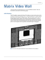
Quick Start Guide


Clarity Matrix Video Wall Installation Guide iii
Copyright © 1 Feb 2013 by Planar Systems, Inc. All rights reserved.
Contents of this publication may not be reproduced in any form without permission of Planar
Systems, Inc.
Trademark Credits
Windows™ is a trademark of Microsoft Corp.
Planar's Big Picture™ is a trademark of Planar Systems, Inc.
Planar’s EasyAxis™ is a trademark of Planar Systems, Inc.
All other names are trademarks or registered trademarks of their respective companies.
Disclaimer
The information contained in this document is subject to change without notice. Planar
Systems, Inc. makes no warranty of any kind with regard to this material. While every
precaution has been taken in the preparation of this manual, the Company shall not be liable
for errors or omissions contained herein or for incidental or consequential damages in
connection with the furnishing, performance, or use of this material.
Warranty and Service Plans
Planar warranty and service plans will help you maximize your investment by providing great
support, display uptime, and performance optimization. From post-sale technical support to
a full suite of depot services, our services are performed by trained Planar employees. When
you purchase a Planar product, you get more than a display, you get the service and support
you need to maximize your investment. To find the latest warranty and service information
regarding your Planar product, please visit http://www.planarcontrolroom.com/support
RoHS Compliance Statement
The Clarity Matrix Video Walls are fully RoHS compliant.
ADA Compliance Statement
The Clarity Matrix Video Walls are compliant with the Americans with Disabilities Act.
Part Number: 020-1220-00A

iv Clarity Matrix Video Wall Installation Guide

Clarity Matrix Video Wall Quick Start Guide i
Table of Contents
Introduction . . . . . . . . . . . . . . . . . . . . . . . . . . . . . . . . . . . . . . . . . . . . . . . . . . . . . . . . . . . . . . . . . . . . . . . . . . . . . . . . . . . . . . .1
Safety Information . . . . . . . . . . . . . . . . . . . . . . . . . . . . . . . . . . . . . . . . . . . . . . . . . . . . . . . . . . . . . . . . . . . . . . . . . . . . . . .2
Important Safety Instructions . . . . . . . . . . . . . . . . . . . . . . . . . . . . . . . . . . . . . . . . . . . . . . . . . . . . . . . . . . . . . . .2
Important EMC Information. . . . . . . . . . . . . . . . . . . . . . . . . . . . . . . . . . . . . . . . . . . . . . . . . . . . . . . . . . . . . . . . .3
European Union Disposal Information. . . . . . . . . . . . . . . . . . . . . . . . . . . . . . . . . . . . . . . . . . . . . . . . . . . . . . .4
Recommended Usage . . . . . . . . . . . . . . . . . . . . . . . . . . . . . . . . . . . . . . . . . . . . . . . . . . . . . . . . . . . . . . . . . . . . . . . . . . . .5
Burn-In Versus Temporary Image Retention . . . . . . . . . . . . . . . . . . . . . . . . . . . . . . . . . . . . . . . . . . . . . . . . .5
Normal Use Thermal Guidelines . . . . . . . . . . . . . . . . . . . . . . . . . . . . . . . . . . . . . . . . . . . . . . . . . . . . . . . . . . . . .6
System Architecture . . . . . . . . . . . . . . . . . . . . . . . . . . . . . . . . . . . . . . . . . . . . . . . . . . . . . . . . . . . . . . . . . . . . . . . . . . . . . .7
EasyAxis Mounts, General Description. . . . . . . . . . . . . . . . . . . . . . . . . . . . . . . . . . . . . . . . . . . . . . . . . . . . . . . . . . . . .8
Matrix Video Wall . . . . . . . . . . . . . . . . . . . . . . . . . . . . . . . . . . . . . . . . . . . . . . . . . . . . . . . . . . . . . . . . . . . . . . . . . . . . . . . . . .9
LCD Modules. . . . . . . . . . . . . . . . . . . . . . . . . . . . . . . . . . . . . . . . . . . . . . . . . . . . . . . . . . . . . . . . . . . . . . . . . . . . . . . . . . . . .9
LCD Mounting Structure. . . . . . . . . . . . . . . . . . . . . . . . . . . . . . . . . . . . . . . . . . . . . . . . . . . . . . . . . . . . . . . . . . . . . . . . 10
Off-Board Equipment and Components . . . . . . . . . . . . . . . . . . . . . . . . . . . . . . . . . . . . . . . . . . . . . . . . . . . . . . . . . 12
Quad Controller Module . . . . . . . . . . . . . . . . . . . . . . . . . . . . . . . . . . . . . . . . . . . . . . . . . . . . . . . . . . . . . . . . . . 12
Power Supply Module . . . . . . . . . . . . . . . . . . . . . . . . . . . . . . . . . . . . . . . . . . . . . . . . . . . . . . . . . . . . . . . . . . . . 13
Installing a Clarity Matrix LCD Video Wall. . . . . . . . . . . . . . . . . . . . . . . . . . . . . . . . . . . . . . . . . . . . . . . . . . . . . . . . 15
Before You Begin. . . . . . . . . . . . . . . . . . . . . . . . . . . . . . . . . . . . . . . . . . . . . . . . . . . . . . . . . . . . . . . . . . . . . . . . . . . . . . . 15
Tools/Equipment List . . . . . . . . . . . . . . . . . . . . . . . . . . . . . . . . . . . . . . . . . . . . . . . . . . . . . . . . . . . . . . . . . . . . . 15
Other Things You May Need . . . . . . . . . . . . . . . . . . . . . . . . . . . . . . . . . . . . . . . . . . . . . . . . . . . . . . . . . . . . . . 15
Plan Your Installation . . . . . . . . . . . . . . . . . . . . . . . . . . . . . . . . . . . . . . . . . . . . . . . . . . . . . . . . . . . . . . . . . . . . . 16
Prepare Your Installation Location. . . . . . . . . . . . . . . . . . . . . . . . . . . . . . . . . . . . . . . . . . . . . . . . . . . . . . . . . 18
Installation Checklist . . . . . . . . . . . . . . . . . . . . . . . . . . . . . . . . . . . . . . . . . . . . . . . . . . . . . . . . . . . . . . . . . . . . . . . . . . . 19
Unpacking and Checking Accessories . . . . . . . . . . . . . . . . . . . . . . . . . . . . . . . . . . . . . . . . . . . . . . . . . . . . . . . . . . . 19
Electronics Box . . . . . . . . . . . . . . . . . . . . . . . . . . . . . . . . . . . . . . . . . . . . . . . . . . . . . . . . . . . . . . . . . . . . . . . . . . . 20
LCD Module Box. . . . . . . . . . . . . . . . . . . . . . . . . . . . . . . . . . . . . . . . . . . . . . . . . . . . . . . . . . . . . . . . . . . . . . . . . . 21
Accessory Box(es). . . . . . . . . . . . . . . . . . . . . . . . . . . . . . . . . . . . . . . . . . . . . . . . . . . . . . . . . . . . . . . . . . . . . . . . . 22
Accessory Kit . . . . . . . . . . . . . . . . . . . . . . . . . . . . . . . . . . . . . . . . . . . . . . . . . . . . . . . . . . . . . . . . . . . . . . . . . . . . . 23
Optional Planar-Supplied Accessories . . . . . . . . . . . . . . . . . . . . . . . . . . . . . . . . . . . . . . . . . . . . . . . . . . . . . 25
Regulatory Information. . . . . . . . . . . . . . . . . . . . . . . . . . . . . . . . . . . . . . . . . . . . . . . . . . . . . . . . . . . . . . . . . . . . . . . . . . 27

Table of Contents
ii Clarity Matrix Video Wall Quick Start Guide

Clarity Matrix Video Wall Quick Start Guide 1
Introduction
The Clarity Matrix LCD Video Wall System uses cutting edge technology to provide a
video wall solution using commercial-grade 46” and 55” full high definition (FHD)
LCDs in a tiled application. The narrow-bezel results in a 5.7mm pixel-to-pixel gap
between images on adjacent panels in a video wall. Each LCD module is an HDTV
format with a 1920 x 1080 resolution. Each LCD module has a 3.6” installed depth and
has an aspect ratio of 1.77 (16:9). It accepts a wide range of input DVI signals from
VGA to UXGA.
The EasyAxisTM mounting system supports landscape and portrait orientation, free-
standing wall deployment and flying wall applications. Because the panels are self-
supporting, Clarity Matrix can support unlimited stacking height.
Caution: This manual is intended for use by qualified service persons and end users with
experience installing LCD displays.

Safety Information
2 Clarity Matrix Video Wall Quick Start Guide
Safety Information
This display was designed with safety in mind. If you don’t heed the safety warnings
and cautions, you could get hurt. The safety warnings are on stickers in various places
in and on the display.
Important Safety Instructions
1Read these instructions.
2Keep these instructions.
3Heed all warnings.
4Follow all instructions.
5Do not use any of the Clarity Matrix LCD Video Wall products near water.
6Clean the LCD screens with an LCD screen cleaner or LCD wipes.
7Do not install near any heat sources such as radiators, heat registers, stoves or
other apparatus (including amplifiers) that produce heat.
8Do not defeat the safety purpose of the polarized or grounding type plug. A
polarized plug has two blades with one wider than the other. A grounding type
plug has two blades and a third grounding prong. The wide blade or the third
prong is provided for your safety. When the provided plug does not fit into your
outlet, consult an electrician for the replacement of the obsolete outlet.
9Protect the power cord from being walked on or pinched particularly at plugs,
convenience receptacles and the point where they exit from any of the Clarity
Matrix LCD Video Wall products.

Safety Information
Clarity Matrix Video Wall Quick Start Guide 3
10 Only use the attachments/accessories specified by the manufacturer.
11 Unplug all Clarity Matrix LCD Video Wall products during lightning storms or
when unused for long periods of time.
12 You must follow all National Electrical Code regulations. In addition, be aware of
local codes and ordinances when installing your system.
13 Refer all servicing to qualified service personnel. Servicing is required when any
of the Clarity Matrix LCD Video Wall products have been damaged in any way,
such as the AC power cord or plug is damaged, liquid has been spilled or objects
have fallen into a product, the products have been exposed to rain or moisture,
do not operate normally or have been dropped.
14 Keep the packing material in case the equipment should ever need to be
shipped.
15 Wall mounts must be secure. The wall must be strong enough to hold all LCD
modules, brackets and cables. Each MX46HD weighs about 39lbs (17.7kg) and
each MX55 LCD module weighs about 50lbs (23kg). With protective optically
bonded glass, the MX46HD LCD module weighs about 49lbs (22.2kg) and the
MX55 LCD module weighs about 65lbs (29kg).
16 Slight pressure on the LCD will cause distortion of the image. Heavier pressure
will cause permanent damage. Clarity Matrix Video Walls should be mounted
where viewers cannot touch the screen or insert small objects in the openings
that will create hazards by contacting bare conductive parts.
Caution: The front polarizer is soft and subject to scratches from sharp objects.
17 The polarizer is a thin sheet of film laminated to the outside layer of glass on the
LCD screen. Take care when handling items near the screen.
Caution: This product contains a lithium battery. There is a risk of explosion if the battery is
replaced by an incorrect type. Dispose of the battery according to the instructions on the
next page.
Important EMC Information
In order to meet Electromagnetic Compatibility (EMC requirements), the installer will
need to add one clip on ferrite bead to the 24VDC power cable near each LCD.

Safety Information
4 Clarity Matrix Video Wall Quick Start Guide
European Union Disposal Information
English
■ Disposal of old Electrical & Electronic Equipment (Applicable throughout
the European Union and other European countries with separate collection
programs)
This symbol found on your product or on its packaging, indicates that
this product should not be treated as household waste when you wish to
dispose of it. Instead, it should be handed over to an applicable collection
point for the recycling of electrical and electronic equipment. By ensuring
this product is disposed of correctly, you will help prevent potential
negative consequences to the environment and human health, which
could otherwise be caused by inappropriate disposal of this product. The
recycling of materials will help to conserve natural resources.
This symbol is only valid in the European Union.
If you wish to discard this product, please contact
your local authorities or dealer and ask for the cor-
rect method of disposal.
Español
■ Deshecho de equipos eléctricos y electrónicos (aplicable a la Unión Euro-
pea y a otros países europeos con programas de reciclaje independientes)
La presencia de este símbolo en el propio producto o en su material de
embalaje, indica que no se debe tratar como residuo doméstico cuando
desee deshacerse de él. En su lugar, debe entregarlo en el punto limpio
correspondiente de reciclaje de equipos eléctricos y electrónicos. Ase-
gurándose de que este producto se desecha de forma correcta, ayudará
a evitar posibles consecuencias negativas para la conservación del
medioambiente y la salud humana, consecuencias que podrían darse si
se deshace del producto de forma inadecuada. El reciclado de materiales
ayuda a conservar los recursos naturales.
Este símbolo solamente es válido en la Unión
Europea.
Si desea deshacerse de este producto, póngase
en contacto con las autoridades locales o con su
distribuidor y pida información sobre el método de
disposición adecuado.
Français
■
Mise au rebut des équipements électriques et électroniques usagés
(Valable dans l’ensemble de l’Union Européenne ainsi que dans les pays
européens disposant de programmes distincts de collecte des déchets)
Ce symbole appliqué sur votre produit ou sur son emballage indique
que ce produit ne doit pas être traité comme un déchet ménager lorsque
vous voulez le mettre au rebut. Il doit au contraire être remis à un site
de collecte agréé pour le recyclage des équipements électriques et
électroniques. En veillant à ce que ce produit soit mis au rebut de façon
adéquate, vous contribuerez à prévenir les conséquences potentiellement
négatives sur l’environnement et sur la santé humaine qui risqueraient
de se produire en cas de mise au rebut inappropriée de ce produit. Le
recyclage des matériaux contribuera également à économiser les res-
sources naturelles.
Ce symbole n’est valable que dans l’Union Européenne.
Si vous souhaitez mettre ce produit au rebut, veuillez
prendre contact avec les autorités locales ou avec votre
revendeur et renseignez-vous sur la méthode de mise
au rebut correcte.
Italiano
■ Smaltimento delle attrezzature elettriche ed elettroniche usate (applicabile
in tutta la Comunità Europea ed altri Paesi Europei che applicano
programmi di raccolta differenziata)
Il simbolo trovato sul prodotto, o sulla sua confezione, indica che il
prodotto non può essere trattato come i domestici quando è il momento
di smaltirlo. Al contrario, deve essere consegnato ad un centro di raccolta
specializzato nel riciclaggio di attrezzature elettriche ed elettroniche. As-
sicurando che il corretto smaltimento di questo prodotto, si aiuterà a preve-
nire potenziali conseguenze negative sull’ambiente e sulla salute umana,
che possono essere provocate da uno scorretto smaltimento di questa
attrezzatura. I materiali riciclati aiuteranno a conservare le risorse naturali.
Questo simbolo è valido solo nell’Unione Europea.
Per smaltire questo prodotto, mettersi in contatto con
le autorità locali – o con il rivenditore – e chiedere
informazioni sul corretto metodo di smaltimento.
Deutsch
■ Entsorgung von elektrischen & elektronischen Altgeräten (geltend für die
europäische Gemeinschaft und andere europäische Länder mit separaten
Sammelprogrammen)
Dieses Symbol, zu finden auf Ihrem Produkt oder dessen Verpackung,
macht Sie darauf aufmerksam, dass dieses Produkt bei der Entsorgung
nicht als Hausmüll behandelt werden darf. Statt dessen sollte es an eine
Sammelstelle zum Recycling von elektrischen und elektronischen Alt-
geräten gegeben werden. Helfen Sie mit, potenziell schädliche Einflüsse
auf Umwelt und Gesundheit, die durch eine unsachgemäße Entsorgung
dieses Produktes entstehen können, zu vermeiden und entsorgen Sie
dieses Produkt ordnungsgemäß. Recycling hilft, natürliche Rohstoffe
einzusparen.
Dieses Symbol ist nur innerhalb der europäischen
Gemeinschaft gültig.
Wenn Sie dieses Produkt entsorgen möchten, wenden
Sie sich bitte an Ihre örtliche Behörde und fragen Sie
nach der ordnungsgemäßen Entsorgungsmethode.
Nederlands
■ Verwijderen van oude elektrische en elektronische apparatuur (toepas-
selijk in de volledige Europese Unie en andere Europese landen met
afzonderlijke programma’s voor afvalverzameling)
Dit symbool dat op het product of zijn verpakking is aangebracht, geeft aan
dat dit product niet mag worden behandeld als huishoudelijk afval als u het
wilt wegwerpen. U moet het afgeven bij een specifiek verzamelpunt voor
de recyclage van elektrische en elektronische apparatuur. Door te garan-
deren dat u dit product op de correcte manier wegwerpt, helpt u potentiële
negatieve gevolgen voor het milieu en de menselijke gezondheid, die
zouden kunnen worden veroorzaakt door een onrechtmatig wegwerpen
van het product, te voorkomen. De recyclage van materialen helpt het
behoud van natuurlijke bronnen.
Dit symbool is alleen geldig in de Europese Unie.
Als u dit product wenst weg te gooien, dient u contact op
te nemen met uw lokale instanties voor details over de
gepaste methode voor afvalverwijdering.
Português
■ Eliminação de equipamentos eléctricos e electrónicos usados (aplicável
na União Europeia e noutros países europeus com programas próprios de
recolha destes equipamentos)
Este símbolo, colocado no produto ou na respectiva embalagem, indica
que o produto não deve ser tratado como lixo doméstico aquando da sua
eliminação. Em vez disso, deve ser entregue num ponto de recolha de eq-
uipamentos eléctricos e electrónicos para posterior reciclagem. Ao garantir
a correcta eliminação deste produto, estará a evitar consequências poten-
cialmente negativas tanto para o ambiente como para a saúde humana. A
reciclagem de materiais ajuda a preservar os recursos naturais.
Este símbolo apenas é válido na União Europeia.
Se quiser eliminar este produto, contacte as enti-
dades locais ou o seu fornecedor para ficar a saber
qual o método de eliminação correcto.
Svenska
■ Avfall av förbrukad elektrisk och elektronisk utrustning (Tillämpbart i
hela Europeiska unionen och andra europeiska länder med separata
samlingsprogram)
Den här symbolen som finns på din product eller på dess förpackning
påvisar att produkten inte ska behandlas som hushållsavfall när du vill
slänga bort den. Istället ska den lämnas över till en lämplig uppsamlings-
punkt för återvinning av elektriska och elektroniska utrustningar. Genom att
tillförsäkra att den här produkten återvinns på ett riktigt sätt hjälper du till
med att förhindra möjliga negative konsekvenser för miljön och mänsklig
hälsa. Det kan annars orsakas på grund av olämplig sophantering av den
här produkten. Återvinning av material kommer att hjälpa till att bevara
naturtillgångar.
Den här symbolen är endast giltig inom den
Europeiska unionen.
Om du vill slänga bort den här produkten ska du
kontakta lokala myndigheter eller återförsäljar, och
fråga efter lämplig avfallsmetod.
Polski
■ Usuwanie zużytego sprzętu elektrycznego i elektronicznego (Dotyczy
krajów Unii Europejskiej i innych krajów europejskich z oddzielnymi
programami zbiórki odpadów)
Obecność tego symbolu na produkcie lub na opakowaniu z produktem
oznacza, że tego produktu nie można wyrzucać razem z odpadkami
domowymi. Należy go przekazać do punktu zbiórki w celu poddania
recyklingowi podzespołów elektrycznych i elektronicznych. Usunięcie tego
produktu w prawidłowy sposób, pomoże w zabezpieczeniu przed negaty-
wnym wpływem odpadów na środowisko i zdrowie ludzi, powodowanym
przez niewłaściwe usuwanie produktu. Przetwarzanie materiałów pomaga
w zachowaniu zasobów naturalnych.
Ten symbol obowiązuje wyłącznie w krajach Unii
Europejskiej.
Informacje dotyczące prawidłowej metody usunięcia
tego produktu, można uzyskać u władz lokalnych lub
u dostawcy.
Suomi
■ Vanhojen sähkö- ja elektroniikkalaitteiden hävittäminen (Soveltuva kaik-
kialla Euroopan unionin alueella, sekä muissa Euroopan maissa, joilla on
erilliset keräysohjelmat)
Jos tuotteessa tai sen pakkauksessa on tämä symboli, sitä ei pidä
hävitettäessä käsitellä tavallisena kotitalousjätteenä, vaan se kuuluu toimit-
taa sähkö- ja elektroniikkalaitteiden kierrätyspisteeseen. Varmistamalla,
että tämä tuote hävitetään asiaankuuluvalla tavalla autat estämään mah-
dollisia ympäristölle ja ihmisille koituvia negatiivisia seuraamuksia, joita
sen vääränlainen hävittäminen voi aiheuttaa. Materiaalien kierrättäminen
auttaa säilyttämään luonnonvaroja.
Tämä symboli on voimassa ainoastaan Euroopan
unionin alueella.
Jos haluat hävittää tämän tuotteen, ota yhteyttä
paikallisiin viranomaisiin tai jälleenmyyjään ja tiedustele
asiaankuuluvia hävittämistoimenpiteitä.

Recommended Usage
Clarity Matrix Video Wall Quick Start Guide 5
Recommended Usage
In order to get the most out of your LCD modules, use the following recommended
guidelines to optimize the display.
Burn-In Versus Temporary Image Retention
Burn-in causes the screen to retain an image essentially forever, with little or no way
to correct the problem. Under normal use, an LCD module will not experience burn-
in, as plasma displays do, nor will it retain images in any way.
Normal use of an LCD module is defined as displaying continuously changing video
patterns or images. However, LCD modules can experience temporary image
retention when recommended usage guidelines are not followed.
What is Temporary Image Retention?
Temporary image retention (TIR) can occur when a static image is displayed
continuously for extended periods of time. An electrical charge differential may build
up between the electrodes of the liquid crystal, which causes a negative-color video
image (color-inverted and brightness-inverted version of the previous image) to be
retained when a new image is displayed. This behavior is true for any LCD device
from any LCD manufacturer.
TIR is not covered under warranty. See standard warranty terms and conditions for
details. Here are some guidelines to help you avoid TIR:
• Use the LCD module to show a screen saver, moving images or still pictures that
change regularly. When using high-contrast images, reposition the images
frequently.
• Turn off the LCD module when it is not in use. There are a few ways to do this
automatically:
• To use the LCD module’s real-time clock, see "Setting the Clock/Scheduling
an Event" on page 55.
• To use your source computer’s Power Options Properties, set up your
computer to turn off the display when not in use. You also need to check the
DPMS checkbox and set the DPMS DELAY box in the BACKLIGHT SETTINGS menu
(MAIN MENU > ADVANCED OPTIONS > BACKLIGHT SETTINGS).
• To use RS232 commands, see "RS232 Communication" on page 69.
Caution: For optimal performance, we suggest turning off the backlight power on the Matrix
MX for four hours per day.

Recommended Usage
6 Clarity Matrix Video Wall Quick Start Guide
Normal Use Thermal Guidelines
Normal use of the LCD module, Quad controller module and power supply module
are defined as operating in the open air to prevent heat buildup, and without direct
or indirect heat sources such as lighting fixtures, heating ducts, or direct sunlight that
can cause the modules to experience high operating temperatures. For all modules,
do not block fans or ventilation openings. If the LCD module will be installed in a
recessed area with an LCD surround or enclosure, ensure adequate openings are
applied for proper air flow and ventilation.
At 2000 meters or below, the maximum ambient operating temperature for the LCD
module cannot be above 35º C nor below the minimum ambient operating
temperature of 0º C. For the Quad controller module and power supply module, the
maximum ambient operating temperature cannot be above 45º C nor below the
minimum ambient operating temperature of 0º C. If one of these conditions exists, it
is up to the installer to ensure that module placement is changed, thermal shielding
is provided and/or additional ventilation is provided to keep the display within its
nominal operating parameters.
Cooling Requirements
For optimal performance, active cooling by the installer should be planned for when
the ambient temperature at the top of the wall is predicted to be above the specified
ambient temperature for the panel. Cooling may be done behind the displays and
depending on the wall configuration, it may be helpful to place air ducts (AC) at
every third display tall.

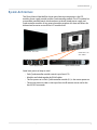
System Architecture
Clarity Matrix Video Wall Quick Start Guide 7
System Architecture
The Clarity Matrix Video Wall has three main electronic components: the LCD
module, power supply module and the Quad controller module. The LCD module has
a removable interface board, which connects to the off-board power supply and
Quad controller modules. Using external modules produces less heat and allows for
reduced and/or easier service of the LCD module itself.
Some basic points to keep in mind:
• Each Quad controller module controls up to four LCDs
• Modules are linked together by RS485 cables
• The first processor in the A Quad controller module (A1) is the master processor
• The master processor takes in the input from the IR remote sensor and/or the
host RS232 commands
LCD module - rear
view - MX55
Power supply module Quad controller module
LCD module - front view

EasyAxis Mounts, General Description
8 Clarity Matrix Video Wall Quick Start Guide
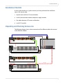
The following example shows the connections for a basic video wall.
EasyAxis Mounts, General Description
Planar-supplied mounts are used to secure the Clarity Matrix Video Wall for display.
Follow these instructions carefully.
Keep in mind the following general installation guidelines:
• Prior to installation, make sure you know where all of the mounting points are
located.
• Follow all safety precautions outlined in this manual.
• Verify the parts received with the list shown in this manual.
B3 B4
B2
A4
A2A1
A3
B1
Quad Controller
Dual Link In Digital 1 Digital 4
Digital 3
Digital 2 Loop Out
Quad Controller
Dual Link In Digital 1 Digital 4
Digital 3
Digital 2 Loop Out
A
B
RS485
RS-232
IR

LCD Modules
Clarity Matrix Video Wall Quick Start Guide 9
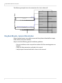
Matrix Video Wall
The Clarity Matrix LCD Video Wall consists of several different modules. These are
described in more detail on the following pages.
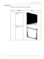
LCD Modules
The LCD module is composed of a basic LCD without a cosmetic enclosure but with a
mechanical subframe for mounting. The LCD module incorporates a simple interface
board designed to distribute off-board power, video and control signals to the LCD
module, keeping depth, weight, heat and points of potential failure to a minimum.
The LCD blade-style module incorporates a bracket that is perfectly paired with the
EasyAxis mount. The LCD module includes EasyAxis adjustment cams that facilitate
precise six-axis alignment ensuring uniform, minimized image-to-image gap.
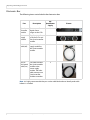
Note: This shows a rear picture of the MX55. The rear of MX46HD will look different.

LCD Mounting Structure
10 Clarity Matrix Video Wall Quick Start Guide
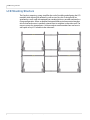
LCD Mounting Structure
The EasyAxis mounting system simplifies the task of installing and aligning the LCD
modules while allowing for efficient in-wall service. EasyAxis is designed to be
attached to a wall, used with optional free-standing bases or secured overhead in a
flying configuration. When assembled, horizontal and vertical connection brackets
ensure that each mount is perfectly spaced from its neighbor in the video wall. The
mount system also incorporates a service mode to accommodate front and rear in-
wall repair of any LCD module in the video wall.

LCD Mounting Structure
Clarity Matrix Video Wall Quick Start Guide 11
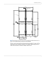
Note: This drawing shows portrait LCD mounts for the MX55. See "Matrix Dimensions" on
page 173 for complete drawings of the MX55 and the MX46HD.
EasyAxis mounts are designed to facilitate the thinnest profile LCD video wall. The
combination of the mount plus the Matrix LCD module’s “blade” design results in
video walls that measure 3.6 inches in depth, screen to wall.
120,1$/*$3
120,1$/*$3
',63/$<287/,1(6
9(57,&$/$/,*10(17
%5$&.(7686(0;
%87721+($'6&5(:6
+25,=217$/$/,*10(17
%5$&.(7686(0;
%87721+($'6&5(:6
.,&.67$1')25
6(59,&(02'(
&(17(5,1*
127&+

Off-Board Equipment and Components
12 Clarity Matrix Video Wall Quick Start Guide
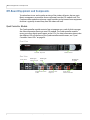
Off-Board Equipment and Components
To reduce heat issues and to make servicing of the video wall easier, the two main
Matrix components are modules that are separate from the LCD module itself. The
Quad controller modules and power supply modules can be housed in an equipment
rack that is typically situated away from the video wall itself.
Quad Controller Module
The Quad controller module contains four microprocessors, each of which manages
the video information flowing to one LCD module. The Quad controller module
routes up to four digital source inputs to the LCDs. For more information about what
the different LEDs on the front of the Quad controller module mean, see "Quad
Controller Status LEDs" on page 58.
Front View
Rear View
Air intake - keep clear Address selector
Power switch DVI-D digital
input or Loop In
DVI-D digital
input
Communication/video
to LCD Air exhaust vents -
keep clear
Power supply
monitor connection
DVI-D Digital
Loop Out

Off-Board Equipment and Components
Clarity Matrix Video Wall Quick Start Guide 13
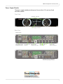
Power Supply Module
The power supply module provides power for up to four LCDs and one Quad
controller module.
Front View
Rear View
Air intakes - keep clear
Power supply test switches
Interface module
power outlets
AC power switch
115/230 VAC 50/60Hz
20A IEC C20 AC input Air exhaust vents -
keep clear Quad controller
module power outlet Power supply
monitor connection
Depending on your configuration,
these two outlets may be covered.

Off-Board Equipment and Components
14 Clarity Matrix Video Wall Quick Start Guide
La page est en cours de chargement...
La page est en cours de chargement...
La page est en cours de chargement...
La page est en cours de chargement...
La page est en cours de chargement...
La page est en cours de chargement...
La page est en cours de chargement...
La page est en cours de chargement...
La page est en cours de chargement...
La page est en cours de chargement...
La page est en cours de chargement...
La page est en cours de chargement...
La page est en cours de chargement...
La page est en cours de chargement...
La page est en cours de chargement...
La page est en cours de chargement...
-
 1
1
-
 2
2
-
 3
3
-
 4
4
-
 5
5
-
 6
6
-
 7
7
-
 8
8
-
 9
9
-
 10
10
-
 11
11
-
 12
12
-
 13
13
-
 14
14
-
 15
15
-
 16
16
-
 17
17
-
 18
18
-
 19
19
-
 20
20
-
 21
21
-
 22
22
-
 23
23
-
 24
24
-
 25
25
-
 26
26
-
 27
27
-
 28
28
-
 29
29
-
 30
30
-
 31
31
-
 32
32
-
 33
33
-
 34
34
-
 35
35
-
 36
36


Planar Clarity MX46HD Guide de démarrage rapide
- Taper
- Guide de démarrage rapide
- Ce manuel convient également à
dans d''autres langues
- italiano: Planar Clarity MX46HD Guida Rapida
- English: Planar Clarity MX46HD Quick start guide
Documents connexes
Autres documents
-
Kimex 160-1010TK4 Manuel utilisateur
-
NEC MultiSync LCD1980SXI Manuel utilisateur
-
ASROCK 4Core1333-eSATA2 Le manuel du propriétaire
-
NEC LCD1935NXM Manuel utilisateur
-
Tote Vision LCD-1411T Owner's Manual & Installation Manual
-
Tote Vision LCD-1044TW Owner's Manual & Installation Manual
-
ASROCK 4CORE1600P35-WIFI PLUS Le manuel du propriétaire
-
-