ASROCK 4Core1333-eSATA2 Le manuel du propriétaire
- Taper
- Le manuel du propriétaire

11
11
1
ASRock 4Core1333-eSATA2 Motherboard
EnglishEnglish
EnglishEnglish
English
Copyright Notice:Copyright Notice:
Copyright Notice:Copyright Notice:
Copyright Notice:
No part of this installation guide may be reproduced, transcribed, transmitted, or trans-
lated in any language, in any form or by any means, except duplication of documen-
tation by the purchaser for backup purpose, without written consent of ASRock Inc.
Products and corporate names appearing in this guide may or may not be registered
trademarks or copyrights of their respective companies, and are used only for identifica-
tion or explanation and to the owners’ benefit, without intent to infringe.
Disclaimer:Disclaimer:
Disclaimer:Disclaimer:
Disclaimer:
Specifications and information contained in this guide are furnished for informational
use only and subject to change without notice, and should not be constructed as a
commitment by ASRock. ASRock assumes no responsibility for any errors or omissions
that may appear in this guide.
With respect to the contents of this guide, ASRock does not provide warranty of any kind,
either expressed or implied, including but not limited to the implied warranties or
conditions of merchantability or fitness for a particular purpose. In no event shall
ASRock, its directors, officers, employees, or agents be liable for any indirect, special,
incidental, or consequential damages (including damages for loss of profits, loss of
business, loss of data, interruption of business and the like), even if ASRock has been
advised of the possibility of such damages arising from any defect or error in the guide
or product.
This device complies with Part 15 of the FCC Rules. Operation is subject to the
following two conditions:
(1) this device may not cause harmful interference, and
(2) this device must accept any interference received, including interference that
may cause undesired operation.
CALIFORNIA, USA ONLY
The Lithium battery adopted on this motherboard contains Perchlorate, a toxic
substance controlled in Perchlorate Best Management Practices (BMP) regulations
passed by the California Legislature. When you discard the Lithium battery in
California, USA, please follow the related regulations in advance.
“Perchlorate Material-special handling may apply, see
www.dtsc.ca.gov/hazardouswaste/perchlorate”
ASRock Website: http://www.asrock.com
Published December 2007
Copyright©2007 ASRock INC. All rights reserved.

22
22
2
ASRock 4Core1333-eSATA2 Motherboard
EnglishEnglish
EnglishEnglish
English
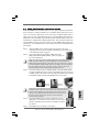
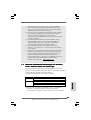
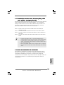
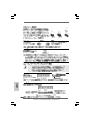
Motherboard LMotherboard L
Motherboard LMotherboard L
Motherboard L
ayoutayout
ayoutayout
ayout
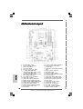
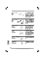
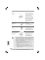
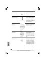
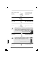
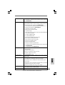
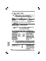
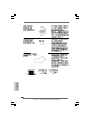
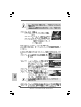
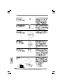
1 PS2_USB_PWR1 Jumper 19 Chassis Speaker Header (SPEAKER 1)
2 ATX 12V Connector (ATX12V1) 20 Front Panel IEEE 1394 Header
3 FSB1 / FSB2 Jumpers (FRONT_1394)
4 775-Pin CPU Socket 21 DeskExpress Hot Plug Detection Header
5 CPU Fan Connector (CPU_FAN1) (IR1)
6 2 x 240-pin DDRII DIMM Slots 22 Floppy Connector (FLOPPY1)
(Dual Channel A: DDRII_1, DDRII_3; Yellow) 23 WiFi Header (WIFI)
7 2 x 240-pin DDRII DIMM Slots 24 Game Port Header (GAME1)
(Dual Channel B: DDRII_2, DDRII_4; Orange) 25 Front Panel Audio Header (HD_AUDIO1)
8 IDE1 Connector (IDE1, Blue) 26 PCI Slots (PCI1 - 3)
9 Clear CMOS Jumper (CLRCMOS1) 27 HDMI_SPDIF Header (HDMI_SPDIF1)
10 South Bridge Controller 28 Internal Audio Connector: CD1 (Black)
11 Chassis Fan Connector (CHA_FAN1) 29 AGI Express Slot (PCI Express x4)
12 SATAII Connector (SATAII_BLUE (Port0)) 30 FSB3 Jumper
13 SATAII Connector (SATAII_ORANGE (Port3)) 31 PCI Express x16 Slot (PCIE2)
14 SATAII Connector (SATAII_RED (Port2)) 32 North Bridge Controller
15 System Panel Header (PANEL1) 33 PCI Express x1 Slot (PCIE1)
16 SATAII Connector (SATAII_BLACK (Port1)) 34 SLI / XFIRE Power Connector
17 USB 2.0 Header (USB4_5, Blue) 35 ATX Power Connector (ATXPWR1)
18 Flash Memory 36 eSATAII Connector (eSATAII)

33
33
3
ASRock 4Core1333-eSATA2 Motherboard
EnglishEnglish
EnglishEnglish
English
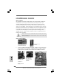
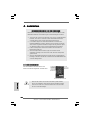
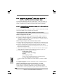
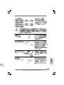
ASRASR
ASRASR
ASR
ock 1394_eSAock 1394_eSA
ock 1394_eSAock 1394_eSA
ock 1394_eSA
TT
TT
T
AII I/O PlusAII I/O Plus
AII I/O PlusAII I/O Plus
AII I/O Plus
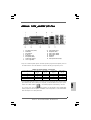
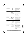
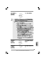
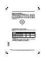
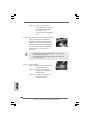
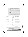
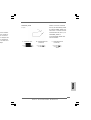
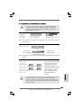
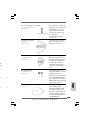
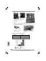
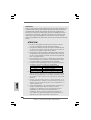
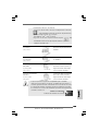
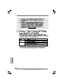
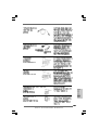
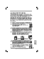
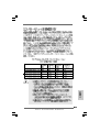
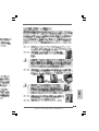
1 PS/2 Mouse Port (Green) * 9 Front Speaker (Lime)
2 Parallel Port 10 Microphone (Pink)
3 IEEE 1394 Port 11 USB 2.0 Ports (USB23)
4 RJ-45 Port 12 USB 2.0 Ports (USB01)
5 Side Speaker (Gray) 13 eSATAII Port
6 Rear Speaker (Black) 14 COM Port
7 Central / Bass (Orange) 15 PS/2 Keyboard Port (Purple)
8 Line In (Light Blue)
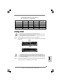
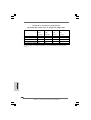
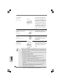
* If you use 2-channel speaker, please connect the speaker’s plug into “Front Speaker Jack”. See
the table below for connection details in accordance with the type of speaker you use.
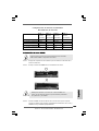
TABLE for Audio Output Connection
Audio Output Channels Front Speaker Rear Speaker Central / Bass Side Speaker
(No. 9) (No. 6) (No. 7) (No. 5)
2 V -- -- --
4 V -- -- V
6V--VV
8 VVVV
* To enable Multi-Streaming function, you need to connect a front panel audio cable to the front
panel audio header. After restarting your computer, you will find “Mixer” tool on your system.
Please select “Mixer ToolBox” , click “Enable playback multi-streaming”, and click
“ok”. Choose “2CH”, “4CH”, “6CH”, or “8CH” and then you are allowed to select “Realtek HDA
Primary output” to use Rear Speaker, Central/Bass, and Front Speaker, or select “Realtek HDA
Audio 2nd output” to use front panel audio.

44
44
4
ASRock 4Core1333-eSATA2 Motherboard
EnglishEnglish
EnglishEnglish
English
1. Introduction1. Introduction
1. Introduction1. Introduction
1. Introduction
Thank you for purchasing ASRock 4Core1333-eSATA2 motherboard, a reliable
motherboard produced under ASRock’s consistently stringent quality control. It de-
livers excellent performance with robust design conforming to ASRock’s commit-
ment to quality and endurance.
This Quick Installation Guide contains introduction of the motherboard and step-by-
step installation guide. More detailed information of the motherboard can be found in
the user manual presented in the Support CD.
Because the motherboard specifications and the BIOS software might be
updated, the content of this manual will be subject to change without
notice. In case any modifications of this manual occur, the updated
version will be available on ASRock website without further notice. You
may find the latest VGA cards and CPU support lists on ASRock website
as well. ASRock website
http://www.asrock.com
If you require technical support related to this motherboard, please visit
our website for specific information about the model you are using.
www.asrock.com/support/index.asp
1.1 P1.1 P
1.1 P1.1 P
1.1 P
ackack
ackack
ack
age Contentsage Contents
age Contentsage Contents
age Contents
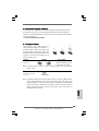
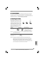
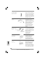
ASRock 4Core1333-eSATA2 Motherboard
(ATX Form Factor: 12.0-in x 9.0-in, 30.5 cm x 22.9 cm)
ASRock 4Core1333-eSATA2 Quick Installation Guide
ASRock 4Core1333-eSATA2 Support CD
One 80-conductor Ultra ATA 66/100 IDE Ribbon Cable
One Ribbon Cable for a 3.5-in Floppy Drive
Two Serial ATA (SATA) Data Cables (Optional)
One Serial ATA (SATA) HDD Power Cable (Optional)
One HDMI_SPDIF Cable (Optional)
One “ASRock 1394_eSATAII I/O Plus” I/O Panel Shield

55
55
5
ASRock 4Core1333-eSATA2 Motherboard
EnglishEnglish
EnglishEnglish
English
1.21.2
1.21.2
1.2
SpecificationsSpecifications
SpecificationsSpecifications
Specifications
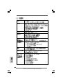
Platform - ATX Form Factor: 12.0-in x 9.0-in, 30.5 cm x 22.9 cm
CPU - LGA 775 for Intel
®
Core
TM
2 Extreme / Core
TM
2 Quad /
Core
TM
2 Duo / Pentium
®
Dual Core / Celeron
®
, supporting
Quad Core Yorkfield and Dual Core Wolfdale processors
- Compatible with all FSB1333/1066/800MHz CPUs
- Supports Hyper-Threading Technology (see CAUTION 1)
- Supports Untied Overclocking Technology (see CAUTION 2)
- Supports EM64T CPU
Chipset - Northbridge: Intel
®
P31/G31
- Southbridge: Intel
®
ICH7R
Memory - Dual Channel DDRII Memory Technology (see CAUTION 3)
- 4 x DDRII DIMM slots (see CAUTION 4)
- Support DDRII800/667 (see CAUTION 5)
- Max. capacity: 4GB (see CAUTION 6)
Hybrid Booster - CPU Frequency Stepless Control (see CAUTION 7)
- ASRock U-COP (see CAUTION 8)
- Boot Failure Guard (B.F.G.)
Expansion Slot - Supports ATI
TM
CrossFire
TM
- 1 x PCI Express x16 slot
- 1 x AGI Express slot (PCI Express x4)
- 1 x PCI Express x1 slot
- 3 x PCI slots
Audio - 7.1 CH Windows
®
Vista
TM
Premium Level HD Audio
(ALC888 Audio Codec)
LAN - PCIE x1 Gigabit LAN 10/100/1000 Mb/s
- Realtek RTL8111B / RTL8111C
- Supports Wake-On-LAN
Rear Panel I/O ASRock 1394_eSATAII I/O Plus
- 1 x PS/2 Mouse Port
- 1 x PS/2 Keyboard Port
- 1 x Serial Port: COM1
- 1 x Parallel Port (ECP/EPP Support)
- 4 x Ready-to-Use USB 2.0 Ports
- 1 x eSATAII Port
- 1 x RJ-45 Port
- 1 x IEEE 1394 Port
- HD Audio Jack: Side Speaker/Rear Speaker/Central/Bass/
Line in/Front Speaker/Microphone (see CAUTION 9)

66
66
6
ASRock 4Core1333-eSATA2 Motherboard
EnglishEnglish
EnglishEnglish
English
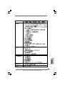
Connector - 4 x SATAII 3.0Gb/s connectors, support RAID (RAID 0,
RAID 1, RAID 10, RAID 5 and Intel Matrix Storage), NCQ and
AHCI functions (see CAUTION 10)
- 1 x eSATAII 3.0Gb/s connector (shared with 1 SATAII
port) (see CAUTION 11)
- 1 x ATA100 IDE connector (supports 2 x IDE devices)
- 1 x Floppy connector
- 1 x DeskExpress Hot Plug Detection header
- 1 x Game header
- 1 x HDMI_SPDIF header
- 1 x IEEE 1394 header
- CPU/Chassis FAN connector
- 24 pin ATX power connector
- 4 pin 12V power connector
- SLI/XFIRE power connector
- CD in header
- Front panel audio connector
- 1 x USB 2.0 header (supports 2 USB 2.0 ports)
(see CAUTION 12)
- 1 x WiFi header (see CAUTION 13)
BIOS Feature - 4Mb AMI BIOS
- AMI Legal BIOS
- Supports “Plug and Play”
- ACPI 1.1 Compliance Wake Up Events
- Supports jumperfree
- AMBIOS 2.3.1 Support
Support CD - Drivers, Utilities, AntiVirus Software (Trial Version)
Hardware - CPU Temperature Sensing
Monitor - Chassis Temperature Sensing
- CPU Fan Tachometer
- Chassis Fan Tachometer
- CPU Quiet Fan
- Voltage Monitoring: +12V, +5V, +3.3V, CPU Vcore
OS - Microsoft
®
Windows
®
2000 / XP / XP 64-bit / Vista
TM
/
Vista
TM
64-bit compliant
Certifications - FCC, CE, WHQL

77
77
7
ASRock 4Core1333-eSATA2 Motherboard
EnglishEnglish
EnglishEnglish
English
CAUTION!
1. About the setting of “Hyper Threading Technology”, please check page
43 of “User Manual” in the support CD.
2. This motherboard supports Untied Overclocking Technology. Please read
“Untied Overclocking Technology” on page 35 for details.
3. This motherboard supports Dual Channel Memory Technology. Before
you implement Dual Channel Memory Technology, make sure to read
the installation guide of memory modules on page 12 for proper
installation.
4. There are memory module installation limitations on this motherboard,
please read “Installation of Memory Modules (DIMM)” on page 12 for
details.
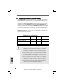
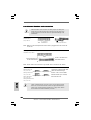
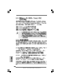
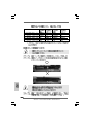
5. Please check the table below for the CPU FSB frequency and its
corresponding memory support frequency.
CPU FSB Frequency Memory Support Frequency
1333 DDRII667, DDRII800
1066 DDRII667, DDRII800
800 DDRII667, DDRII800
6. Due to the operating system limitation, the actual memory size may be
less than 4GB for the reservation for system usage under Windows
®
XP
and Windows
®
Vista
TM
. For Windows
®
XP 64-bit and Windows
®
Vista
TM
64-
bit with 64-bit CPU, there is no such limitation.
7. Although this motherboard offers stepless control, it is not recom-
mended to perform over-clocking. Frequencies other than the recom-
mended CPU bus frequencies may cause the instability of the system
or damage the CPU.
8. While CPU overheat is detected, the system will automatically shutdown.
Before you resume the system, please check if the CPU fan on the
motherboard functions properly and unplug the power cord, then plug it
back again. To improve heat dissipation, remember to spray thermal
grease between the CPU and the heatsink when you install the PC
system.
9. For microphone input, this motherboard supports both stereo and mono
modes. For audio output, this motherboard supports 2-channel, 4-
channel, 6-channel, and 8-channel modes. Please check the table on
page 3 for proper connection.
WARNING
Please realize that there is a certain risk involved with overclocking, including adjusting
the setting in the BIOS, applying Untied Overclocking Technology, or using the third-
party overclocking tools. Overclocking may affect your system stability, or even
cause damage to the components and devices of your system. It should be done at
your own risk and expense. We are not responsible for possible damage caused by
overclocking.

88
88
8
ASRock 4Core1333-eSATA2 Motherboard
EnglishEnglish
EnglishEnglish
English
1.31.3
1.31.3
1.3
Minimum Hardware RMinimum Hardware R
Minimum Hardware RMinimum Hardware R
Minimum Hardware R
equirement Tequirement T
equirement Tequirement T
equirement T
able for Wable for W
able for Wable for W
able for W
indowsindows
indowsindows
indows
®®
®®
®
VistaVista
VistaVista
Vista
TMTM
TMTM
TM
Premium 2007 and Basic Logo Premium 2007 and Basic Logo
Premium 2007 and Basic Logo Premium 2007 and Basic Logo
Premium 2007 and Basic Logo
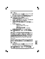
For system integrators and users who purchase this motherboard and
plan to submit Windows
®
Vista
TM
Premium 2007 and Basic logo, please
follow below table for minimum hardware requirements.
CPU Celeron 420
Memory 1GB system memory (Premium)
512MB Single Channel (Basic)
VGA DX9.0 with WDDM Driver
with 128bit VGA memory (Premium)
with 64bit VGA memory (Basic)
* After June 1, 2007, all Windows
®
Vista
TM
systems are required to meet above
minimum hardware requirements in order to qualify for Windows
®
Vista
TM
Premium
2007 logo.
10. Before installing SATAII hard disk to SATAII connector, please read the
“SATAII Hard Disk Setup Guide” on page 28 to adjust your SATAII hard
disk drive to SATAII mode. You can also connect SATA hard disk to SATAII
connector directly.
11. This motherboard supports eSATAII interface, the external SATAII
specification. Please read “eSATAII Interface Introduction” on page 26
for details about eSATAII and eSATAII installation procedures.
12. Power Management for USB 2.0 works fine under Microsoft
®
Windows
®
Vista
TM
64-bit / Vista
TM
/ XP 64-bit / XP SP1 or SP2 / 2000 SP4.
13. WiFi header supports WiFi+AP function with ASRock WiFi-802.11g or
WiFi-802.11n module, an easy-to-use wireless local area network
(WLAN) adapter. It allows you to create a wireless environment and
enjoy the convenience of wireless network connectivity. Please visit our
website for the availability of ASRock WiFi-802.11g or WiFi-802.11n
module.
ASRock website http://www.asrock.com

99
99
9
ASRock 4Core1333-eSATA2 Motherboard
2.2.
2.2.
2.
InstallationInstallation
InstallationInstallation
Installation
Pre-installation PrecautionsPre-installation Precautions
Pre-installation PrecautionsPre-installation Precautions
Pre-installation Precautions
Take note of the following precautions before you install mother-
board components or change any motherboard settings.
1. Unplug the power cord from the wall socket before touching any
component. Failure to do so may cause severe damage to the
motherboard, peripherals, and/or components.
2. To avoid damaging the motherboard components due to static
electricity, NEVER place your motherboard directly on the carpet
or the like. Also remember to use a grounded wrist strap or touch
a safety grounded object before you handle components.
3. Hold components by the edges and do not touch the ICs.
4. Whenever you uninstall any component, place it on a grounded
antstatic pad or in the bag that comes with the component.
5. When placing screws into the screw holes to secure the
motherboard to the chassis, please do not over-tighten the
screws! Doing so may damage the motherboard.
2.12.1
2.12.1
2.1
CPU InstallationCPU Installation
CPU InstallationCPU Installation
CPU Installation
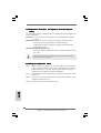
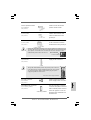
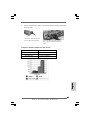
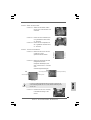
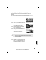
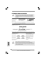
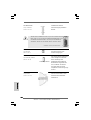
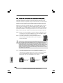
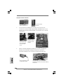
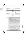
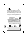
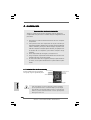
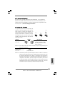
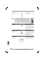
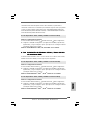
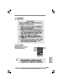
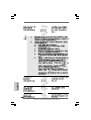
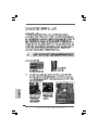
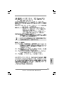
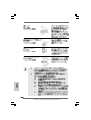
For the installation of Intel 775-LAND CPU,
please follow the steps below.
Before you insert the 775-LAND CPU into the socket, please check if
the CPU surface is unclean or if there is any bent pin on the socket.
Do not force to insert the CPU into the socket if above situation is
found. Otherwise, the CPU will be seriously damaged.
775-Pin Socket Overview
EnglishEnglish
EnglishEnglish
English

1010
1010
10
ASRock 4Core1333-eSATA2 Motherboard
EnglishEnglish
EnglishEnglish
English
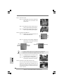
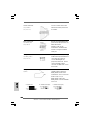
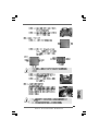
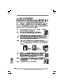
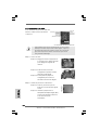
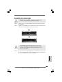
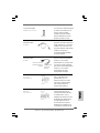
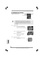
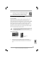
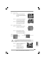
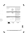
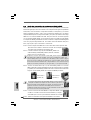
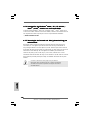
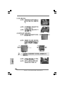
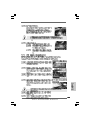
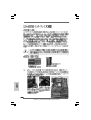
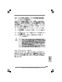
Step 1. Open the socket:
Step 1-1. Disengaging the lever by depressing
down and out on the hook to clear
retention tab.
Step 1-2. Rotate the load lever to fully open po-
sition at approximately 135 degrees.
Step 1-3. Rotate the load plate to fully open po-
sition at approximately 100 degrees.
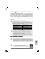
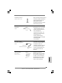
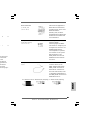
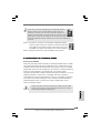
Step 2. Insert the 775-LAND CPU:
Step 2-1. Hold the CPU by the edges where are
marked with black lines.
Step 2-2. Orient the CPU with IHS (Integrated
Heat Sink) up. Locate Pin1 and the two
orientation key notches.
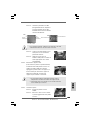
For proper inserting, please ensure to match the two orientation key
notches of the CPU with the two alignment keys of the socket.
Step 2-3. Carefully place the CPU into the socket
by using a purely vertical motion.
Step 2-4. Verify that the CPU is within the socket
and properly mated to the orient keys.
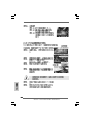
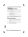
Step 3. Remove PnP Cap (Pick and Place Cap):
Use your left hand index finger and thumb to
support the load plate edge, engage PnP cap
with right hand thumb and peel the cap from the
socket while pressing on center of PnP cap to
assist in removal.
black line
black line
775-Pin Socket
Pin1
alignment key
alignment key
Pin1
orientation
key notch
orientation
key notch
775-LAND CPU

1111
1111
11
ASRock 4Core1333-eSATA2 Motherboard
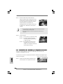
1. It is recommended to use the cap tab to handle and avoid kicking
off the PnP cap.
2. This cap must be placed if returning the motherboard for after
service.
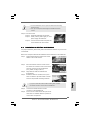
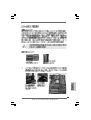
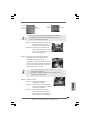
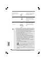
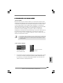
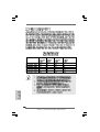
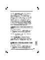
Step 4. Close the socket:
Step 4-1. Rotate the load plate onto the IHS.
Step 4-2. While pressing down lightly on load
plate, engage the load lever.
Step 4-3. Secure load lever with load plate tab
under retention tab of load lever.
2.22.2
2.22.2
2.2
Installation of CPU Fan and HeatsinkInstallation of CPU Fan and Heatsink
Installation of CPU Fan and HeatsinkInstallation of CPU Fan and Heatsink
Installation of CPU Fan and Heatsink
For proper installation, please kindly refer to the instruction manuals of your CPU fan
and heatsink.
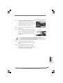
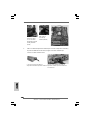
Below is an example to illustrate the installation of the heatsink for 775-LAND CPU.
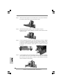
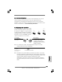
Step 1. Apply thermal interface material onto center
of IHS on the socket surface.
Step 2. Place the heatsink onto the socket. Ensure
fan cables are oriented on side closest to the
CPU fan connector on the motherboard
(CPU_FAN1, see page 2, No. 5).
Step 3. Align fasteners with the motherboard
throughholes.
Step 4. Rotate the fastener clockwise, then press
down on fastener caps with thumb to install
and lock. Repeat with remaining fasteners.
If you press down the fasteners without rotating them clockwise,
the heatsink cannot be secured on the motherboard.
Step 5. Connect fan header with the CPU fan
connector on the motherboard.
Step 6. Secure excess cable with tie-wrap to ensure
cable does not interfere with fan operation or
contact other components.
EnglishEnglish
EnglishEnglish
English

1212
1212
12
ASRock 4Core1333-eSATA2 Motherboard
EnglishEnglish
EnglishEnglish
English
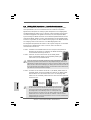
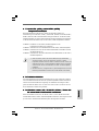
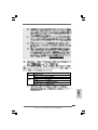
2.3 Installation of Memory Modules (DIMM)2.3 Installation of Memory Modules (DIMM)
2.3 Installation of Memory Modules (DIMM)2.3 Installation of Memory Modules (DIMM)
2.3 Installation of Memory Modules (DIMM)
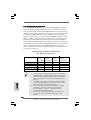
4Core1333-eSATA2 motherboard provides four 240-pin DDRII (Double Data
Rate II) DIMM slots, and supports Dual Channel Memory Technology. For dual
channel configuration, you always need to install identical (the same brand,
speed, size and chip-type) DDRII DIMM pair in the slots of the same color. In other
words, you have to install identical DDRII DIMM pair in Dual Channel A (DDRII_1
and DDRII_3; Yellow slots; see p.2 No.6) or identical DDRII DIMM pair in Dual
Channel B (DDRII_2 and DDRII_4; Orange slots; see p.2 No.7), so that Dual
Channel Memory Technology can be activated. This motherboard also allows
you to install four DDRII DIMMs for dual channel configuration, and please install
identical DDRII DIMMs in all four slots. You may refer to the Dual Channel
Memory Configuration Table below.
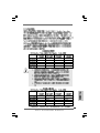
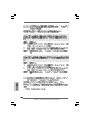
Dual Channel Memory Configurations
(DS: Double Side, SS: Single Side)
1. If you want to install two memory modules, for optimal compatibility
and reliability, it is recommended to install them in the slots of the
same color. In other words, install them either in the set of yellow
slots (DDRII_1 and DDRII_3), or in the set of orange slots (DDRII_2
and DDRII_4).
2. If only one memory module or three memory modules are installed
in the DDRII DIMM slots on this motherboard, it is unable to activate
the Dual Channel Memory Technology.
3. If a pair of memory modules is NOT installed in the same Dual
Channel, for example, installing a pair of memory modules in DDRII_1
and DDRII_2, it is unable to activate the Dual Channel Memory
Technology .
4. It is not allowed to install a DDR memory module into DDRII slot;
otherwise, this motherboard and DIMM may be damaged.
DDRII_1 DDRII_2 DDRII_3 DDRII_4
(Yellow Slot) (Orange Slot) (Yellow Slot) (Orange Slot)
2 memory modules SS X SS X
2 memory modules DS X DS X
2 memory modules X SS X SS
2 memory modules X DS X DS
4 memory modules SS SS SS SS

1313
1313
13
ASRock 4Core1333-eSATA2 Motherboard
EnglishEnglish
EnglishEnglish
English
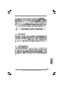
Recommended Memory Configurations
(DS: Double Side, SS: Single Side)
DDRII_1 DDRII_2 DDRII_3 DDRII_4
(Yellow Slot) (Orange Slot) (Yellow Slot) (Orange Slot)
1 memory module DS/SS* X X X
2 memory modules DS/SS X DS/SS X
2 memory modules X DS/SS X DS/SS
3 memory modules SS SS DS/SS X
4 memory modules SS SS SS SS
* If you only install one memory module, you can install it to any one of the four slots.
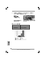
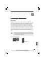
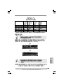
Installing a DIMMInstalling a DIMM
Installing a DIMMInstalling a DIMM
Installing a DIMM
Please make sure to disconnect power supply before adding or
removing DIMMs or the system components.
Step 1. Unlock a DIMM slot by pressing the retaining clips outward.
Step 2. Align a DIMM on the slot such that the notch on the DIMM matches the break
on the slot.
The DIMM only fits in one correct orientation. It will cause permanent
damage to the motherboard and the DIMM if you force the DIMM into the slot
at incorrect orientation.
Step 3. Firmly insert the DIMM into the slot until the retaining clips at both ends fully
snap back in place and the DIMM is properly seated.

1414
1414
14
ASRock 4Core1333-eSATA2 Motherboard
EnglishEnglish
EnglishEnglish
English
2.4 Expansion Slots (PCI, PCI Express, and AGI Express2.4 Expansion Slots (PCI, PCI Express, and AGI Express
2.4 Expansion Slots (PCI, PCI Express, and AGI Express2.4 Expansion Slots (PCI, PCI Express, and AGI Express
2.4 Expansion Slots (PCI, PCI Express, and AGI Express
Slots) Slots)
Slots) Slots)
Slots)
There are 3 PCI slots, 2 PCI Express slots, and 1 AGI Express slot (PCI Express x4)
on this motherboard.
PCI slots: PCI slots are used to install expansion cards that have the 32-bit PCI
interface.
PCIE Slots: PCIE1 (PCIE x1 slot) is used for PCI Express cards with x1 lane
width cards, such as Gigabit LAN card, SATA2 card, etc.
PCIE2 (PCIE x16 slot) is used for PCI Express cards with x16 lane
width graphics cards.
AGI Express slot (PCI Express x4):
AGI Express slot (PCI Express x4) is used to install PCI Express expan-
sion cards.
If you plan to install only one PCI Express card on this motherboard, please
install it on PCIE2 (PCIE x16 slot).
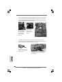
Installing an expansion cardInstalling an expansion card
Installing an expansion cardInstalling an expansion card
Installing an expansion card
Step 1. Before installing the expansion card, please make sure that the power
supply is switched off or the power cord is unplugged. Please read the
documentation of the expansion card and make necessary hardware
settings for the card before you start the installation.
Step 2. Remove the bracket facing the slot that you intend to use. Keep the screws
for later use.
Step 3. Align the card connector with the slot and press firmly until the card is
completely seated on the slot.
Step 4. Fasten the card to the chassis with screws.

1515
1515
15
ASRock 4Core1333-eSATA2 Motherboard
EnglishEnglish
EnglishEnglish
English
2.5 CrossFire2.5 CrossFire
2.5 CrossFire2.5 CrossFire
2.5 CrossFire
TMTM
TMTM
TM
Operation Guide Operation Guide
Operation Guide Operation Guide
Operation Guide
This motherboard supports CrossFire
TM
feature. CrossFire
TM
technology offers the
most advantageous means available of combining multiple high performance Graphics
Processing Units (GPU) in a single PC. Combining a range of different operating
modes with intelligent software design and an innovative interconnect mechanism,
CrossFire
TM
enables the highest possible level of performance and image quality in
any 3D application. Currently CrossFire
TM
feature is supported with Windows
®
XP
with Service Pack 2 and Vista
TM
OS. Please check AMD website for ATI
TM
CrossFire
TM
driver updates.
1. If a customer incorrectly configures their system they will not see the
performance benefits of CrossFire
TM
. All three CrossFire
TM
components, a
CrossFire
TM
Ready graphics card, a CrossFire
TM
Ready motherboard and a
CrossFire
TM
Edition co-processor graphics card, must be installed correctly to
benefit from the CrossFire
TM
multi-GPU platform.
2. If you pair a 12-pipe CrossFire
TM
Edition card with a 16-pipe card, both cards will
operate as 12-pipe cards while in CrossFire
TM
mode.
What graphics cards work with CrossFire
TM
?
A complete CrossFire
TM
system requires a CrossFire
TM
Ready motherboard, a
CrossFire
TM
Edition graphics card and a compatible standard Radeon (CrossFire
TM
Ready) graphics card from the same series, or two CrossFire
TM
Ready cards. This
applies to cards from ATI
TM
or any of its partners.
Cards For AGI Express Slot Cards For PCIE2 Slot
Radeon X2600Pro Series Radeon X2600Pro Series
Radeon X2600XT Series Radeon X2600XT Series
Radeon X1950Pro Series Radeon X1950Pro Series
Radeon X1950XTX Series Radeon X1950XTX CrossFire
TM
Edition
Radeon X1800 Series Radeon X1800 CrossFire
TM
Edition
Enjoy the benefit of CrossFireEnjoy the benefit of CrossFire
Enjoy the benefit of CrossFireEnjoy the benefit of CrossFire
Enjoy the benefit of CrossFire
TMTM
TMTM
TM
Currently, ATI
TM
has released Radeon X2600Pro, X2600XT, X1950Pro, X1950XTX
and X1800 CrossFire
TM
cards, which require different methods to enable CrossFire
TM
feature. In below procedures, we use Radeon X2600XT as the example graphics card.
For other CrossFire
TM
cards that ATI
TM
has released or will release in the future, please
refer to ATI
TM
graphics card manuals for detailed installation guide.
It is recommended to use 500-Watt power supply or greater
to perform the benefit of CrossFire
TM
feature.
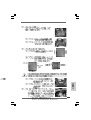
Step 1. Connect to the system power supply. Please connect a hard disk power
connector to SLI/XFIRE Power connector on this motherboard.

1616
1616
16
ASRock 4Core1333-eSATA2 Motherboard
EnglishEnglish
EnglishEnglish
English
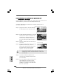
Step 2. Install one Radeon graphics card to PCIE2 slot. For the proper installation
procedures, please refer to section “Expansion Slots”.
Step 3. Install the other Radeon graphics card to AGI Express slot (PCI
Express x4). For the proper installation procedures, please refer to section
“Expansion Slots”.
Step 4. Connect two Radeon graphics cards by installing two CrossFire
TM
Bridge
on CrossFire
TM
Bridge Interconnects on the top of Radeon graphics cards.
(CrossFire
TM
Bridge is provided with the graphics card you purchase, not
bundled with this motherboard. Please refer to your graphics card vendor
for details.)
Step 5. Connect the DVI monitor cable to the DVI connector on the Radeon graphics
card on PCIE2 slot. (You may use the DVI to D-Sub adapter to convert the
DVI connector to D-Sub interface, and then connect the D-Sub monitor
cable to the DVI to D-Sub adapter.)
CrossFire
TM
Bridge

1717
1717
17
ASRock 4Core1333-eSATA2 Motherboard
EnglishEnglish
EnglishEnglish
English
Step 6. Power on your computer and boot into OS.
Step 7. Remove the ATI
TM
driver if you have any VGA driver installed in your system.
The Catalyst Uninstaller is an optional download. We recommend using this
utility to uninstall any previously installed Catalyst drivers prior to installation.
Please check AMD website for ATI
TM
driver updates.
Step 8. Install the required drivers to your system.
For Windows
®
XP OS:
A. ATI
TM
recommends Windows
®
XP Service Pack 2 or higher to be
installed (If you have Windows
®
XP Service Pack 2 or higher installed
in your system, there is no need to download it again):
http://www.microsoft.com/windowsxp/sp2/default.mspx
B. You must have Microsoft .NET Framework installed prior to
downloading and installing the CATALYST Control Center. Please
check Microsoft website for details.
For Windows
®
Vista
TM
OS:
Install the CATALYST Control Center. Please check Microsoft website for
details.
Step 9. Restart your computer.
Step 10. Install the VGA card drivers to your system, and restart your computer.
Then you will find “ATI Catalyst Control Center” on your Windows
®
taskbar.
ATI Catalyst Control Center
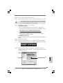
Step 11. Double-click “ATI Catalyst Control Center”. Click “View”, and select
“Advanced View”. Click “CrossFire
TM
”, and then set the option “Enable
CrossFire
TM
” to “Yes”.
View
CrossFire
TM
Enable CrossFire
TM

1818
1818
18
ASRock 4Core1333-eSATA2 Motherboard
EnglishEnglish
EnglishEnglish
English
Although you have selected the option “Enable CrossFire
TM
”, the CrossFire
TM
function may not work actually. Your computer will automatically reboot. After
restarting your computer, please confirm whether the option “Enable CrossFire
TM
”
in “ATI Catalyst Control Center” is selected or not; if not, please select it again,
and then you are able to enjoy the benefit of CrossFire
TM
feature.
Step 12. You can freely enjoy the benefit of CrossFire
TM
feature.
* CrossFire
TM
appearing here is a registered trademark of ATI
TM
Technologies Inc., and is used
only for identification or explanation and to the owners’ benefit, without intent to infringe.
* For further information of ATI
TM
CrossFire
TM
technology, please check AMD website for updates
and details.

1919
1919
19
ASRock 4Core1333-eSATA2 Motherboard
EnglishEnglish
EnglishEnglish
English
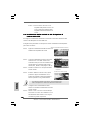
2.6 Surround Display Feature2.6 Surround Display Feature
2.6 Surround Display Feature2.6 Surround Display Feature
2.6 Surround Display Feature
This motherboard supports Surround Display upgrade. With the external add-on
PCI Express VGA card, you can easily enjoy the benefits of Surround Display
feature. For the detailed instruction, please refer to the document at the following
path in the Support CD:
..\ Surround Display Information
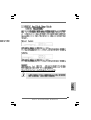
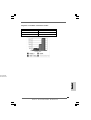
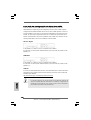
2.7 Jumpers Setup2.7 Jumpers Setup
2.7 Jumpers Setup2.7 Jumpers Setup
2.7 Jumpers Setup
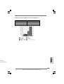
The illustration shows how jumpers are
setup. When the jumper cap is placed on
pins, the jumper is “Short”. If no jumper cap
is placed on pins, the jumper is “Open”. The
illustration shows a 3-pin jumper whose pin1
and pin2 are “Short” when jumper cap is
placed on these 2 pins.
Jumper Setting Description
PS2_USB_PWR1 Short pin2, pin3 to enable
(see p.2 No. 1) +5VSB (standby) for PS/2
or USB wake up events.
Note: To select +5VSB, it requires 2 Amp and higher standby current provided by
power supply.
Clear CMOS
(CLRCMOS1, 2-pin jumper)
(see p.2 No. 9)
Note: CLRCMOS1 allows you to clear the data in CMOS. The data in CMOS includes
system setup information such as system password, date, time, and system
setup parameters. To clear and reset the system parameters to default setup,
please turn off the computer and unplug the power cord from the power
supply. After waiting for 15 seconds, use a jumper cap to short 2 pins on
CLRCMOS1 for 5 seconds.
2-pin jumper
Short Open

2020
2020
20
ASRock 4Core1333-eSATA2 Motherboard
EnglishEnglish
EnglishEnglish
English
2.8 Onboard Headers and Connectors2.8 Onboard Headers and Connectors
2.8 Onboard Headers and Connectors2.8 Onboard Headers and Connectors
2.8 Onboard Headers and Connectors
Onboard headers and connectors are NOT jumpers. Do NOT place
jumper caps over these headers and connectors. Placing jumper caps
over the headers and connectors will cause permanent damage of the
motherboard!
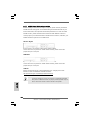
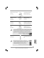
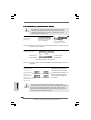
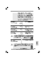
FDD connector
(33-pin FLOPPY1)
(see p.2 No. 22)
Note: Make sure the red-striped side of the cable is plugged into Pin1 side of the
connector.
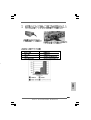
Primary IDE connector (Blue)
(39-pin IDE1, see p.2 No. 8)
Note: Please refer to the instruction of your IDE device vendor for the details.
Serial ATAII Connectors These four Serial ATAII (SATAII)
(SATAII_BLUE (Port0): connectors support SATA data
see p.2, No. 12) cables for internal storage
(SATAII_BLACK (Port1): devices. The current SATAII
see p.2, No. 16) interface allows up to 3.0 Gb/s
(SATAII_RED (Port2): data transfer rate.
see p.2, No. 14)
(SATAII_ORANGE (Port3):
see p.2, No. 13)
SATAII_ORANGE (Port3) connector can be used for internal storage
device or be connected to eSATAII connector to support eSATAII device.
Please read “eSATAII Interface Introduction” on page 26 for details
about eSATAII and eSATAII installation procedures.
connect the black end
to the IDE devices
connect the blue end
to the motherboard
SATAII_BLUE (Port0) SATAII_ORANGE (Port3)
80-conductor ATA 66/100 cable
SATAII_BLACK (Port1) SATAII_RED (Port2)
the red-striped side to Pin1
La page est en cours de chargement...
La page est en cours de chargement...
La page est en cours de chargement...
La page est en cours de chargement...
La page est en cours de chargement...
La page est en cours de chargement...
La page est en cours de chargement...
La page est en cours de chargement...
La page est en cours de chargement...
La page est en cours de chargement...
La page est en cours de chargement...
La page est en cours de chargement...
La page est en cours de chargement...
La page est en cours de chargement...
La page est en cours de chargement...
La page est en cours de chargement...
La page est en cours de chargement...
La page est en cours de chargement...
La page est en cours de chargement...
La page est en cours de chargement...
La page est en cours de chargement...
La page est en cours de chargement...
La page est en cours de chargement...
La page est en cours de chargement...
La page est en cours de chargement...
La page est en cours de chargement...
La page est en cours de chargement...
La page est en cours de chargement...
La page est en cours de chargement...
La page est en cours de chargement...
La page est en cours de chargement...
La page est en cours de chargement...
La page est en cours de chargement...
La page est en cours de chargement...
La page est en cours de chargement...
La page est en cours de chargement...
La page est en cours de chargement...
La page est en cours de chargement...
La page est en cours de chargement...
La page est en cours de chargement...
La page est en cours de chargement...
La page est en cours de chargement...
La page est en cours de chargement...
La page est en cours de chargement...
La page est en cours de chargement...
La page est en cours de chargement...
La page est en cours de chargement...
La page est en cours de chargement...
La page est en cours de chargement...
La page est en cours de chargement...
La page est en cours de chargement...
La page est en cours de chargement...
La page est en cours de chargement...
La page est en cours de chargement...
La page est en cours de chargement...
La page est en cours de chargement...
La page est en cours de chargement...
La page est en cours de chargement...
La page est en cours de chargement...
La page est en cours de chargement...
La page est en cours de chargement...
La page est en cours de chargement...
La page est en cours de chargement...
La page est en cours de chargement...
La page est en cours de chargement...
La page est en cours de chargement...
La page est en cours de chargement...
La page est en cours de chargement...
La page est en cours de chargement...
La page est en cours de chargement...
La page est en cours de chargement...
La page est en cours de chargement...
La page est en cours de chargement...
La page est en cours de chargement...
La page est en cours de chargement...
La page est en cours de chargement...
La page est en cours de chargement...
La page est en cours de chargement...
La page est en cours de chargement...
La page est en cours de chargement...
La page est en cours de chargement...
La page est en cours de chargement...
La page est en cours de chargement...
La page est en cours de chargement...
La page est en cours de chargement...
La page est en cours de chargement...
La page est en cours de chargement...
La page est en cours de chargement...
La page est en cours de chargement...
La page est en cours de chargement...
La page est en cours de chargement...
La page est en cours de chargement...
La page est en cours de chargement...
La page est en cours de chargement...
La page est en cours de chargement...
La page est en cours de chargement...
La page est en cours de chargement...
La page est en cours de chargement...
La page est en cours de chargement...
La page est en cours de chargement...
La page est en cours de chargement...
La page est en cours de chargement...
La page est en cours de chargement...
La page est en cours de chargement...
La page est en cours de chargement...
La page est en cours de chargement...
La page est en cours de chargement...
La page est en cours de chargement...
La page est en cours de chargement...
La page est en cours de chargement...
La page est en cours de chargement...
La page est en cours de chargement...
La page est en cours de chargement...
La page est en cours de chargement...
La page est en cours de chargement...
La page est en cours de chargement...
La page est en cours de chargement...
La page est en cours de chargement...
La page est en cours de chargement...
La page est en cours de chargement...
La page est en cours de chargement...
La page est en cours de chargement...
La page est en cours de chargement...
La page est en cours de chargement...
La page est en cours de chargement...
La page est en cours de chargement...
La page est en cours de chargement...
La page est en cours de chargement...
La page est en cours de chargement...
La page est en cours de chargement...
La page est en cours de chargement...
La page est en cours de chargement...
La page est en cours de chargement...
La page est en cours de chargement...
La page est en cours de chargement...
La page est en cours de chargement...
La page est en cours de chargement...
La page est en cours de chargement...
La page est en cours de chargement...
La page est en cours de chargement...
La page est en cours de chargement...
La page est en cours de chargement...
La page est en cours de chargement...
La page est en cours de chargement...
La page est en cours de chargement...
La page est en cours de chargement...
La page est en cours de chargement...
La page est en cours de chargement...
La page est en cours de chargement...
La page est en cours de chargement...
La page est en cours de chargement...
La page est en cours de chargement...
La page est en cours de chargement...
La page est en cours de chargement...
La page est en cours de chargement...
La page est en cours de chargement...
La page est en cours de chargement...
La page est en cours de chargement...
La page est en cours de chargement...
La page est en cours de chargement...
La page est en cours de chargement...
La page est en cours de chargement...
La page est en cours de chargement...
La page est en cours de chargement...
La page est en cours de chargement...
La page est en cours de chargement...
La page est en cours de chargement...
La page est en cours de chargement...
La page est en cours de chargement...
La page est en cours de chargement...
La page est en cours de chargement...
La page est en cours de chargement...
La page est en cours de chargement...
La page est en cours de chargement...
La page est en cours de chargement...
La page est en cours de chargement...
La page est en cours de chargement...
La page est en cours de chargement...
La page est en cours de chargement...
La page est en cours de chargement...
La page est en cours de chargement...
La page est en cours de chargement...
La page est en cours de chargement...
La page est en cours de chargement...
La page est en cours de chargement...
La page est en cours de chargement...
La page est en cours de chargement...
La page est en cours de chargement...
La page est en cours de chargement...
La page est en cours de chargement...
La page est en cours de chargement...
La page est en cours de chargement...
La page est en cours de chargement...
La page est en cours de chargement...
La page est en cours de chargement...
La page est en cours de chargement...
La page est en cours de chargement...
La page est en cours de chargement...
La page est en cours de chargement...
La page est en cours de chargement...
La page est en cours de chargement...
La page est en cours de chargement...
La page est en cours de chargement...
La page est en cours de chargement...
La page est en cours de chargement...
La page est en cours de chargement...
La page est en cours de chargement...
La page est en cours de chargement...
-
 1
1
-
 2
2
-
 3
3
-
 4
4
-
 5
5
-
 6
6
-
 7
7
-
 8
8
-
 9
9
-
 10
10
-
 11
11
-
 12
12
-
 13
13
-
 14
14
-
 15
15
-
 16
16
-
 17
17
-
 18
18
-
 19
19
-
 20
20
-
 21
21
-
 22
22
-
 23
23
-
 24
24
-
 25
25
-
 26
26
-
 27
27
-
 28
28
-
 29
29
-
 30
30
-
 31
31
-
 32
32
-
 33
33
-
 34
34
-
 35
35
-
 36
36
-
 37
37
-
 38
38
-
 39
39
-
 40
40
-
 41
41
-
 42
42
-
 43
43
-
 44
44
-
 45
45
-
 46
46
-
 47
47
-
 48
48
-
 49
49
-
 50
50
-
 51
51
-
 52
52
-
 53
53
-
 54
54
-
 55
55
-
 56
56
-
 57
57
-
 58
58
-
 59
59
-
 60
60
-
 61
61
-
 62
62
-
 63
63
-
 64
64
-
 65
65
-
 66
66
-
 67
67
-
 68
68
-
 69
69
-
 70
70
-
 71
71
-
 72
72
-
 73
73
-
 74
74
-
 75
75
-
 76
76
-
 77
77
-
 78
78
-
 79
79
-
 80
80
-
 81
81
-
 82
82
-
 83
83
-
 84
84
-
 85
85
-
 86
86
-
 87
87
-
 88
88
-
 89
89
-
 90
90
-
 91
91
-
 92
92
-
 93
93
-
 94
94
-
 95
95
-
 96
96
-
 97
97
-
 98
98
-
 99
99
-
 100
100
-
 101
101
-
 102
102
-
 103
103
-
 104
104
-
 105
105
-
 106
106
-
 107
107
-
 108
108
-
 109
109
-
 110
110
-
 111
111
-
 112
112
-
 113
113
-
 114
114
-
 115
115
-
 116
116
-
 117
117
-
 118
118
-
 119
119
-
 120
120
-
 121
121
-
 122
122
-
 123
123
-
 124
124
-
 125
125
-
 126
126
-
 127
127
-
 128
128
-
 129
129
-
 130
130
-
 131
131
-
 132
132
-
 133
133
-
 134
134
-
 135
135
-
 136
136
-
 137
137
-
 138
138
-
 139
139
-
 140
140
-
 141
141
-
 142
142
-
 143
143
-
 144
144
-
 145
145
-
 146
146
-
 147
147
-
 148
148
-
 149
149
-
 150
150
-
 151
151
-
 152
152
-
 153
153
-
 154
154
-
 155
155
-
 156
156
-
 157
157
-
 158
158
-
 159
159
-
 160
160
-
 161
161
-
 162
162
-
 163
163
-
 164
164
-
 165
165
-
 166
166
-
 167
167
-
 168
168
-
 169
169
-
 170
170
-
 171
171
-
 172
172
-
 173
173
-
 174
174
-
 175
175
-
 176
176
-
 177
177
-
 178
178
-
 179
179
-
 180
180
-
 181
181
-
 182
182
-
 183
183
-
 184
184
-
 185
185
-
 186
186
-
 187
187
-
 188
188
-
 189
189
-
 190
190
-
 191
191
-
 192
192
-
 193
193
-
 194
194
-
 195
195
-
 196
196
-
 197
197
-
 198
198
-
 199
199
-
 200
200
-
 201
201
-
 202
202
-
 203
203
-
 204
204
-
 205
205
-
 206
206
-
 207
207
-
 208
208
-
 209
209
-
 210
210
-
 211
211
-
 212
212
-
 213
213
-
 214
214
-
 215
215
-
 216
216
-
 217
217
-
 218
218
-
 219
219
-
 220
220
-
 221
221
-
 222
222
-
 223
223
-
 224
224
-
 225
225
-
 226
226
-
 227
227
-
 228
228


ASROCK 4Core1333-eSATA2 Le manuel du propriétaire
- Taper
- Le manuel du propriétaire
dans d''autres langues
Documents connexes
-
ASROCK 775TWINS-HDTV Le manuel du propriétaire
-
ASROCK ALIVENF5-ESATA2 PLUS - V1.0 Le manuel du propriétaire
-
ASROCK CONROE1333-1394 Le manuel du propriétaire
-
ASROCK 775XFire-eSATA2 Le manuel du propriétaire
-
ASROCK ALIVEDUAL-ESATA2 Le manuel du propriétaire
-
ASROCK 4Core1333-GLAN Manuel utilisateur
-
ASROCK ALIVEXFIRE-ESATA2 R3.0_987 Le manuel du propriétaire
-
ASROCK 2Core1333-2.66G Le manuel du propriétaire
-
ASROCK P4FSB1333-650 Le manuel du propriétaire
-
ASROCK 2Core1333DVI-2.66G Le manuel du propriétaire