Planar PT3290PW Manuel utilisateur
- Catégorie
- Moniteurs à écran tactile
- Taper
- Manuel utilisateur


The information contained in this document is subject to change without notice.
This document contains proprietary information that is protected by copyright. All rights
are reserved. No part of this document may be reproduced,translated to another language
or stored in a retrieval system, or transmitted by any means, electronic, mechanical,
photocopying, recording, or otherwise, without prior written permission. Windows is a registered
trademark of Microsoft, Inc. Other brand or product names are trademarks of their respective
holders.
The test results show that this device meets the FCC rules. Those limits are set to protect
residential areas from the devices with harmful emission. This device will produce, use and
radiate radio frequency energy. In addition, failure to follow the user’s manual to install or use
this device might produce harmful interference with radio communication. Not withstanding
the foregoing, it does not guarantee that this type of harmful interference does not occur in
some special installations. The interference caused by this device to the reception of radio
or television signals may be verifi ed by turning it on and off. Any changes or modifi cations to
this TFT edge-lit LED LCD would void the user’s authority to operate this device.
Important Waste Disposal Information
http://www.planar.com/about/green/.
Please recycle or dispose of all electronic waste in accordance with local, state, and federal laws.
Additional resources can be found online at
The crossed-out wheelie bin symbol is to notify consumers in areas subject to Waste Electrical and
Electronic Equipment (WEEE) Directive 2012/19/EU that the product was placed on the market after
August 13, 2005 and must not be disposed of with other waste. Separate collection and recycling of
electronic waste at the time of disposal ensures that it is recycled in a manner that minimizes impacts
to human health and the environment. For more information about the proper disposal of electronic waste,
please contact your local authority, your household waste disposal service, or the seller from whom you
purchased the product.
Industry Canada (ICES-003): This Class B digital apparatus complies with Canadian ICES-003.
Cet appareil numérique de la classe B est conforme à la norme NMB-003 du Canada.

Table of Contents
Usage Notice
Precautions............................................................................................................................. 1
Introduction
About PT3290PW ................................................................................................................... 3
Touch Screen for PT3290PW ................................................................................................. 3
Package Overview ...................................................................................................... 4
Installation
Product Overview ........................................................................................................ 5
Front View .............................................................................................................. 5
Bottom View ........................................................................................................... 5
VESA Mount for Your Monitor ...................................................................................... 6
Start Your Installation .................................................................................................. 7
Connecting the Display (Figure 8.1) ............................................................................. 8
(Figure 8.1) ............................................................................................................. 9
User Controls
Rear Panel Controls ...................................................................................................10
How to Use the OSD Menus .......................................................................................11
On-Screen Display Menus ..........................................................................................12
Appendix
Troubleshooting ..........................................................................................................16
Warning Signal ...........................................................................................................17
No Signal ...............................................................................................................17
Going to Sleep........................................................................................................17
Out of Range ..........................................................................................................17
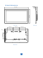
Product Dimensions ...................................................................................................18
Compatibility Modes ...................................................................................................19
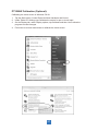
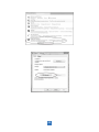
Touch Screen Driver Installation .................................................................................20
PT3290PW Calibration Tool Install ..........................................................................21
PT3290PW Driver Install Instructions ......................................................................23
Technical Support ................................................................................................................ 24
OSD/Power Lock out ..................................................................................................11
Control through RS232 ...............................................................................................13
RJ45 pin defination in display side..........................................................................13
COM port setting in PC side...................................................................................13
COM command structure from PC side ..................................................................13
Configuration..........................................................................................................14
Command format....................................................................................................15

Usage Notice
Precautions
Follow all warnings, precautions and maintenance as recommended in this user’s manual to
maximize the life of your unit.
Do:
� Turn off the product before cleaning.
� Touch screen surface may be cleaned using a soft clean cloth moistened with mild
window glass commercial cleaners or 50/50 mixture of water and isopropyl alcohol.
� Use a soft cloth moistened with mild detergent to clean the display housing.
� Disconnect the power plug from AC outlet if the product is not going to be used for
an extended period of time.
Don’t:
� Do not touch the LED Display screen surface with sharp or hard objects.
� Do not use abrasive cleaners, waxes or solvents for your cleaning.
� Do not operate the product under the following conditions:
○ Extremely hot, cold or humid environment.
○ Areas susceptible to excessive dust and dirt.
○ Near any appliance generating a strong magnetic field.
○ In direct sunlight.
1
� Do not use over 16 hours per day.
� If smoke, abnormal noise or odor emits from your Touch LED LCD Monitor, remove the power cord
immediately and call your service center.
� Never remove the rear cover of your Touch LED LCD Monitor. The display unit inside contains
high-voltage parts and may cause electric shock.
� Never try to repair your Touch LED LCD Monitor yourself. Always call your service center or a
qualified technician to fix it.
� Due to safety concerns, if the VESA mounting kit is purchased separately, pleasemake sure the
mounting kit is UL-listed, and replaceable only by service personnel.

Consignes de sécurité
Respectez tous les avertissements, les précautions et conseils d’entretien recommandés dans ce
manuel de l’utilisateur pour maximiser la durée de vie de votre appareil.
A faire :
Éteindre le produit avant de le nettoyer.
La surface de l'écran tactile peut être nettoyée avec un chiffon doux et propre imprégné d’un
nettoyant doux du commerce pour vitres ou d'un mélange à 50/50 d'alcool isopropylique et
d'eau.
Utilisez un chiffon doux imprégné d'un détergeant doux pour nettoyer le carter de l'affichage.
Débranchez la fiche d’alimentation de la prise de courant secteur si le produit ne doit pas être
utilisé pendant une période prolongée.
A ne pas faire :
Ne touchez pas la surface de l’écran LED avec des objets coupants ou durs.
N'utilisez pas des produits de nettoyage abrasifs, de la cire ou des solvants pour le nettoyage.
N’utilisez pas le produit dans les conditions suivantes :
○ Environnement extrêmement chaud, froid ou humide.
○ Endroits poussiéreux ou sales.
○ Près d’appareils générant un fort champ magnétique.
○ Sous la lumière directe du soleil.
2
Ne pas utiliser plus de 16 heures par jour.
Si de la fumée, un bruit anormal ou une odeur s'échappait de votre moniteur LCD LED,
débranchez immédiatement le cordon d'alimentation et appelez votre centre de réparation..
Ne retirez jamais le couvercle arrière de votre moniteur LCD LED. L’unité d’affichage contient
des éléments où circule un voltage élevé et présentant un risque d'électrocution.
N’essayez jamais de réparer vous-même votre moniteur LCD LED. Faites toujours appel à votre
centre de service ou à un technicien qualifié pour toute réparation.
Pour des raisons de sécurité, si vous achetez séparément le kit de fixation VESA,
assurez-vous que celui-ci est certifié UL, et qu’il peut être remplacé uniquement par
un technicien qualifié.
Usage Notice

Introduction
About PT3290PW
The PT3290PW is a 31.5" flat panel screen with an active matrix, thin-film transistor (TFT)
edge-lit LED LCD.
This unit is to be used as commercial and light industrial equipment only.
Features include:
• Direct Analog signal input
• Direct Digital signal input
• Active matrix TFT edge-lit LED LCD technology
• 1920 x 1080 resolution
• 31.5" viewable display area - 16:9 aspect ratio
• 31.47 ~ 67.5 KHz horizontal scan
• 47 ~ 63 Hz high refresh rate
• 0.3637mm x 0.3637mm pixel pitch
• Auto adjustment function
• Multilingual OSD user control
• 600mm x 200mm and 200mmx200mm VESA mount
• Projected Capactive touch screen with USB controller
• Audio - 5W x 2
Touch Screen for PT3290PW
• Projected Capacitive 10-point touch screen
• Interface: USB controller
• Transmittance: 84%(min)
• HID: Windows® 7/8/10
• Driver:
— Windows® 7/8/10: For Projected Capacitive the driver is a mouse emulation driver. If your
Windows version is Windows 7 or later, there is no need to install this driver. There is a HID
touch digitizer build-in driver in Windows 7/8/10.
— Linux kernel 2.6.x (32 bit & 64 bit), Apple ® Mac OS
3

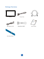
Package Overview
4
droC rewoPyalpsiD
USB Cable (A to B) User’s Guide
xxxxxxxxx / xxxxxxxxx
xxxxxxxxx
USER’S GUIDE
www.planartouch.com
RJ45 TO RJ45 CABLE
DisplayPort CABLE
Quick Start Guide
HID Compliant - Driverless!
No drivers needed when using USB!

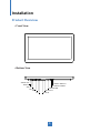
Installation
Product Overview
• Front View
• Bottom View
5
AC INPUT POWER
DVI-IN
VGA IN
AUDIO IN
TOUCH USB
HDMI RJ45 OUT
RJ45 IN
ON/OFF SWITCH
DP
AUDIO OUT

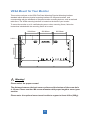
VESA Mount for Your Monitor
This monitor conforms to the VESA Flat Panel Mounting Physical Mounting Interface
standard which de fines a physical mounting interface for flat panel monitors, and
corresponding with the standards of flat panel monitor mounting devices, such as wall and
table arms. The VESA mounting interface is located on the back of your monitor.
To mount the monitor on a UL certi fied swing arm or other mounting fixture, follow the
instructions included with the mounting fixture to be used.
! Warning!
Please select the proper screws!
The distance between the back cover surface and the bottom of the screw hole
is 10 mm. Please use four M4 screws diameter with proper length to mount your
monitor.
Please note: the optional mount must be able to support at least 44 lbs (20Kg).
6
200.00mm 200.00mm 200.00mm
200.00mm
8-M4

USB
Power
DP
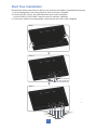
Start Your Installation
Please follow these instructions so that you can hook up the cables to associated connectors.
1. Lay the display flat on an even surface as seen in the step 1 diagram.
2. Connect the DP, Power, and USB cables as seen in step 2 diagram.
Connect RJ45 to RJ45 Cable if remote control is required. (Optional)
Step 1
DVI
Audio-In
Step 2
7
VGA
Step 3
Audio-Out
USB
Power
3. Connect the cables to the appropriate connectors as seen in the step 3 diagram.
RJ45 OUT
RJ45 INDP HDMI
RJ45 IN (Optional)
RJ45 OUT (Optional)

8
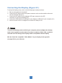
Connecting the Display (Figure 8.1)
To setup this display, please refer to the following figure and procedures.
1. Be sure all equipment is turned off.
2. Connect the AC power cord to the power connector on the monitor and the other end
into an electrical outlet (8.1).
3. Connect the DP cable from the display’s DP input connector to the DP
connector of your host computer (8.1).
4. Connect the USB cable from USB port of your display to USB port of your computer (8.1).
5. Once the touch screen is con figured, the monitor is ready for use.
! Notice!
To ensure the display works well with your computer, please confi gure the display
mode of your graphics card to make it less than or equal to 1920 x 1080 resolution
and make sure the timing of the display mode is compatible with the display.
We have listed the compatible “Video Modes” of your display in the appendix
(on page 15) for your reference.

9
(Figure 8.1)
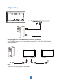
Controlling the PT3290PW monitor via RS232 (Optional)
The PT3290PW monitor can be controlled by connecting to a PC with a RJ45 terminal
diagramed below:
Note:
Two COM Ports are reserved for this option.
Please refer to the RS232 section starting on page 13 for more information.
RJ45 In RJ45 Out RJ45 In

10
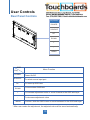
User Controls
Rear Panel Controls
OSD
Key Menu Function
Key Name
POWER
SOURCE
UP
DOWN
+
-
MENU
POWER
SOURCE
UP
DOWN
+
-
MENU
Power On/Off
To select source input port
To move up OSD item
To move down OSD item
To increase adjustment value or move forward to the OSD sub-layer
To decrease adjustment value
To show / hide the OSD menu or move backward to the OSD sub-layer
* After user makes the adjustment, the adjusted value will be saved automatically.

11
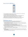
How to Use the OSD Menus
1. Press the “MENU” button to pop up the “on-screen menu” and press “Up” or “Down” button
to select among the four functions in the main menu.
2. Choose the sub-layer menus by pressing the “+” button.
3. Press “Up” or “Down” button to select the adjustment items in the sub-layer menu.If the
adjustment items have a sub-layer menu,Press the “+” button to choose it also.
4. Adjust the value of the adjustment items by pressing the “ + ” or “ - ” button.
5. With the OSD menu on screen, press “ Menu” button to return main menu or exit OSD.
6. The OSD menu will automatically close, if you have left it idle for a pre-set time.
1. To Lock the OSD / Power menu buttons, please follow the instructions below
(Please note: the monitor has to be turned ON with a valid signal pre-set)
(a.)Press and hold “Menu” and “Up” keys simultaneously for 3 seconds, then OSD will be locked
and show "OSD Locked" 3 seconds.
(b.)Press and hold “Menu” and “Down” keys simultaneously for 3 seconds, then Power button will
be locked and show "Power button Locked" 3 seconds.
2. To Unlock the OSD / Power menu buttons, please follow the instructions below
(Please note: the monitor has to be turned ON with a valid signal pre-set)
(a.)Press and hold “Menu” and “Up” keys simultaneously for 3 seconds, then OSD will be unlocked
and show "OSD Unlocked" 3 seconds.
(b.)Press and hold “Menu” and “Down” keys simultaneously for 3 seconds, then Power button will be
unlocked and show "Power button Unlocked" 3 seconds.
Please note:
a. When the OSD lock function is selected, this indicates that all the buttons except “power”button
are now disabled.
b. When the Power button lock function is selected, this indicates that the power key is disabled;user
can not to turn off the monitor by “Power” key.
Key Name
POWER
SOURCE
UP
DOWN
+
-
MENU
OSD/Power Lock out

12
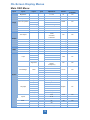
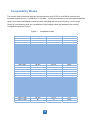
On-Screen Display Menus
Main OSD Menu:
Layer1 Layer2 Layer3 Layer4 Adjustment Default reset
(to default)
Brightness 0 ~ 100 70 Yes
Contrast 0 ~ 100 50 Yes
Sharpness -4 ~ 4 0 Yes
9300k 9300k
6500k 6500k
User Settings User Settings
R 0 ~ 100 100 No
G 0 ~ 100 100 No
B0 ~ 100 100 No
Phase 0 ~ 100 Per timing Yes
Clock 0 ~ 100 Per timing Yes
H Position 0 ~ 100 Per timing Yes
V Position 0 ~ 100 Per timing Yes
Volume 0 ~ 30 15 Yes
Mute On/Off Off Yes
Audio Select Default/Audio Jack Default Yes
VGA/ VGA/
DVI/ DVI/
HDMI/ HDMI/
DP DP
3 sec 3 sec
6 sec 6 sec
12 sec 12 sec
30 sec 30 sec
H Position 0 ~ 100 50 Yes
V Position 0 ~ 100 50 Yes
Transparency 0 ~ 10 0 Yes
English English
Espanol Espanol
Deutsch Deutsch
French French
Italian Italian
日本語 日本語
中文 中文
Reset Reset
Monitor ID Broadcast(1) ~ 9 Broadcast Yes
Language
English
No
Phase,
Clock,
V Position,
H Position
Width,
Height,
V Frequency
NA
NA
Osd Settings
Timer
12 sec
Yes
NA
Audio
System
Input
VGA
No
Signal info
Image
Color Temp. Menu
9300k
Yes
Display
Auto Adjust
NA
Aspect
Full
DCR On
16:10
4:3
Full Yes
Off
Off Yes

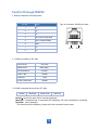
Control through RS232
1. RJ45 pin definition on display side:
Pin No. Name
1 NC
2 NC
3 NC
4 RXD (Receiving data)
5 TXD (Transmit data)
6 GND
7 NC
8 NC
2.1 COM port setting in PC side:
PROTOCOL RS-232C
BAUD RATE 9600 (bps)
DATA LENGTH 8 (bits)
PARITY BIT NONE
STOP BIT 1 (bit)
FLOW CONTROL NONE
Pin 8 Pin 1
2.2 COM command structure from PC side:
Header Message Check code Delimiter
Header: specify the start of this command package.
Message: command body, it comprises OP code page, OP code, parameters, checksum.
Delimiter: end of package.
* The detail structure statement, please refer the command format sheet.
13
Type of connector: RJ45 8-pin male:

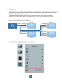
3. Configuration
14
These monitors can be daisy-chained together. Except Broadcast mode, every monitor in this chain
should have a unique ID which can be chosen by the OSD menu. The maximum ID number of
monitors in this daisy-chain is up to 9.
If Individual mode, IDs should set correctly, then SW tool could control them individually.
Otherwise, the conflict will happen. If Broadcast mode, monitors ID setting doesn’t matter.
Monitor ID can be adjusted by OSD menu as below:
Daisy-chained RS232 with one COM port
PC ID1
RS 232
ID3
RS 232
ID2
RS 232
ID4
RS 232
RS232 IN
Display 1
RS232 IN
RS232 IN RS232 IN
RS232 OUT RS232 OUT
RS232 OUT
Display 2
Display 3 Display 4
COM1

4. Command format
15
Byte0 Byte1 Byte2 Byte3 Byte4 Byte5 Byte6 Byte7 Byte8 Byte9 Byte10 Byte11 Byte12 Byte13 Byte14 Byte15 Byte16 BYTE17
SOH Fix code MonitorID('*') STX ETX Checksum
Write 0x01 0x30 0x2A ('*') 0x30 0x45('E') 0x30('0') 0x41('A') 0x02 0x30 0x31 0x31 0x30 0x30 0x30 0x36 0x34 0x03
XOR from Byte1 to Byte16 0x0D
Read 0x01 0x30 0x2A ('*') 0x30 0x43('C') 0x30('0') 0x36('6') 0x02 0x30 0x31 0x31 0x30 0x03
XOR from Byte1 to Byte16 0x0D
POWER OFF 0x01 0x30 0x2A 0x30 0x45 0x30 0x41 0x02 0x30 0x30 0x30 0x33 0x30 0x30 0x30 0x30 0x03 0x1C 0x0D
POWER ON 0x01 0x30 0x2A 0x30 0x45 0x30 0x41 0x02 0x30 0x30 0x30 0x33 0x30 0x30 0x30 0x31 0x03 0x1D 0x0D
VGA 0x01 0x30 0x2A 0x30 0x45 0x30 0x41 0x02 0x30 0x32 0x43 0x42 0x30 0x30 0x30 0x30 0x03 0x1C 0x0D
DVI 0x01 0x30 0x2A 0x30 0x45 0x30 0x41 0x02 0x30 0x32 0x43 0x42 0x30 0x30 0x30 0x31 0x03 0x1D 0x0D
HDMI 0x01 0x30 0x2A 0x30 0x45 0x30 0x41 0x02 0x30 0x32 0x43 0x42 0x30 0x30 0x30 0x32 0x03 0x1E 0x0D
DISPLAY PORT 0x01 0x30 0x2A 0x30 0x45 0x30 0x41 0x02 0x30 0x32 0x43 0x42 0x30 0x30 0x30 0x33 0x03 0x1F 0x0D
Header Message
Fix code
OP code page
OP code
Parameters
None
Operaon
Delimiter

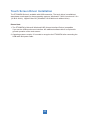
16
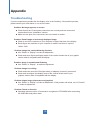
Appendix
Troubleshooting
If you are experiencing trouble with the display, refer to the following. If the problem persists,
please contact your local dealer or our service center.
Problem: No image appears on screen.
► Check that all the I/O and power connectors are correctly and well connected
as described in the “Installation” section.
► Make sure the pins of the connectors are not crooked or broken.
Problem: Partial Image or incorrectly displayed image.
► Check to see if the resolution of your computer is higher than that of the display.
► Recon figure the resolution of your computer to make it less than or equal to
1920 x 1080.
Problem: Image has vertical fl ickering line bars.
► Use “Phase” in “Display” to make an adjustment.
► Check and recon figure the display mode of the vertical refresh rate of your graphic
card to make it compatible with the display.
Problem: Image is unstable and fl ickering
► Use “Phase” in “Display” to make an adjustment.
Problem: Image is scrolling
► Check and make sure the VGA signal cable (or adapter) is securely connected.
► Check and reconfigure the display mode of the vertical refresh rate of your
graphics card to make it compatible with the display.
Problem: Vague image (characters and graphics)
► Use “Phase” in “Display” to make an adjustment. If this problem still exists, use “H Position”
to make an adjustment.
Problem: Touch no function
► Operating systems require 15 seconds to recognize the PT3290PW after connecting
the USB cable and power cable.

Warning Signal
If you see warning messages on your screen, this means that the display cannot receive a
clean signal from the computer graphics card.
Below are the three kinds of Warning Signal. Please check the cable connections or contact
your local dealer or our service center for more information.
No Signal
This message means that the display has been powered on but it cannot receive any signal
from the computer graphics card. Check all the power switches, power cables, and video cable.
Going to Sleep
The display is under the power saving mode. In addition, the display will enter power saving
mode when experiencing a sudden signal disconnecting problem.
The monitor can be activated by pressing any keyboard, triggering the mouse or touching
the screen.
Out of Range
This message means that the signal of the computer graphic card is not compatible with
the display. When the signal is not included in the “Video Modes” list we have listed in the
Appendices of this manual, the monitor will display this message.
17
La page est en cours de chargement...
La page est en cours de chargement...
La page est en cours de chargement...
La page est en cours de chargement...
La page est en cours de chargement...
La page est en cours de chargement...
La page est en cours de chargement...
La page est en cours de chargement...
-
 1
1
-
 2
2
-
 3
3
-
 4
4
-
 5
5
-
 6
6
-
 7
7
-
 8
8
-
 9
9
-
 10
10
-
 11
11
-
 12
12
-
 13
13
-
 14
14
-
 15
15
-
 16
16
-
 17
17
-
 18
18
-
 19
19
-
 20
20
-
 21
21
-
 22
22
-
 23
23
-
 24
24
-
 25
25
-
 26
26
-
 27
27
-
 28
28


Planar PT3290PW Manuel utilisateur
- Catégorie
- Moniteurs à écran tactile
- Taper
- Manuel utilisateur
dans d''autres langues
- English: Planar PT3290PW User manual
Documents connexes
Autres documents
-
 Winmate R19L100-67FTP Manuel utilisateur
-
 Winmate R15L100-MLC3HB Manuel utilisateur
-
Denon DN-HC4500 Manuel utilisateur
-
 ADEUNIS MODBUS V1.0.1 Mode d'emploi
-
ViewSonic CDE8600 Mode d'emploi
-
ViewSonic IFP7500 Mode d'emploi
-
ViewSonic CDE4320-S Mode d'emploi
-
ViewSonic CDE5510-S Mode d'emploi
-
ViewSonic CDE3204-S Mode d'emploi
-
ViewSonic CDE6510 Mode d'emploi


