
1
CATALYST GAUGE REPLACEMENT KIT
P/N 900596-00
Rev. NC, 12/2015
HEARTH PRODUCTS
KITS AND ACCESSORIES
KIT CONTENTS
1 ea. Catalytic Temperature Gauge
1 ea. Catalytic Thermopile
1 ea. Instruction Sheet
TOOLS NEEDED
None
INSTALLATION INSTRUCTIONS FOR INSTALLING A REPLACEMENT CATALYST GAUGE KIT
FOR USE WITH VILLA VISTA™, WRT4826WH, AND BIS® PANORAMA WOOD-BURNING FIREPLACES
Catalyst Gauge Replacement Kit
Cat. No. Where Used
J8004 Villa Vista™, WRT4826WH, and BIS® Panorama
Table 1
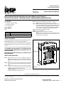
Figure 1
GENERAL INFORMATION
The Catalyst Gauge Replacement Kit is a replacement part kit for Villa Vista™,
WRT4826WH, and BIS® Panorama wood-burning fireplaces.
If you encounter any problems, need clarification of these instructions or
are not qualified to properly install this kit, contact your local distributor
or dealer.
Read this instruction sheet in its entirety before beginning the installation.
ALL WARNINGS AND PRECAUTIONS IN THE INSTALLATION AND
OPERATION MANUAL PROVIDED WITH THE APPLIANCE APPLY TO
THESE INSTRUCTIONS.
SHUT DOWN THE APPLIANCE AND ALLOW IT TO COMPLETELY COOL
BEFORE PROCEEDING.
INSTALLATION INSTRUCTIONS
Step 1. Open the lower louver to access the temperature gauge (see
Figure 1). Lift the gauge up to remove it from the bracket. View
the back of the gauge and remove the nuts that are securing the
wires.
Step 2. Remove the louver in the top opening by holding it straight and
raising it until it unlatches from the support screws (inside the
frame).
Step 3. Reach behind the vent pipe (next to flue) and use a phillips
screwdriver* to remove the (2) screws that secure the existing
thermopile. Pull the thermopile out of the unit.
*Alternate Method: Use a wench to remove the nut on the
thermopile, then pull it out of the bracket.
NOTE: DIAGRAMS & ILLUSTRATIONS ARE NOT TO SCALE.
IHP reserves the right to make changes at any time, without notice, in design, materials, specifications, prices and also to discontinue colors, styles and products. Consult your local distributor
for fireplace code information.
Innovative Hearth Products
1508 Elm Hill Pike, Suite 108 • Nashville, TN 37210
12/08/2015
Printed in U.S.A. © 2015 Innovative Hearth Products
P/N 900596-00 Rev. NC 12/2015
Step 4. Install the new thermopile (reverse process in step 3).
NOTE: Ensure wire runs down the left side of the unit.
Step 5. From the lower opening, grab the wire that is attached to the
thermopile and connect its ring-terminal to the back of the new
gauge. Place the connector attached to the red wire on the posi-
tive (+) connection and the connector attached to the white wire
on the negative (-) connection (on the back of the gauge).
Step 6. Slide the new gauge into the bracket.
Step 7. Close the lower louver.
Step 8. Reinstall the top louver into the top opening.
NOTE: Hold louver straight and as close as possible to the inside
of the top frame, then lower the louver until it attaches to the
support screws inside the frame.
Thermopile
THERMOPILE
GAUGE
Gauge

2
P/N 900596-00
Rév. NC, 12/2015
KITS ET ACCESSOIRES
DE FOYER
INCLUS DANS LE KIT
1 - Indicateur de température du catalyseur
1 - Thermopile du catalyseur
1 - Feuillet d’instructions
OUTILS NÉCESSAIRES
Aucun
INSTRUCTIONS D’INSTALLATION POUR LE REMPLACEMENT DE L’INDICATEUR DE TEMPÉRATURE DU CATALYSEUR
POUR UTILISATION AVEC LES FOYERS À BOIS VILLA VISTAMC, WRT4826WH, ET BISMD PANORAMA
INDICATEUR DE TEMPÉRATURE DU CATALYSEUR
Nº cat. Où l’utiliser
J8004 Villa VistaMC, WRT4826WH, et BISMD Panorama
Tableau 1
INFORMATIONS GÉNÉRALES
L’ensemble de remplacement de l’indicateur de température du cataly-
seur est conçu pour les cheminées à bois Villa VistaMC, WRT4826WH et
BISMD Panorama.
Si vous avez un problème quelconque, avez besoin de clarification pour
ces instructions ou n’êtes pas qualifié pour installer correctement ce
ventilateur, contactez votre distributeur ou détaillant local.
Lisez toute les instructions sur cette feuille avant de commencer
l’installation.
LES MISES EN GARDE ET AVERTISSEMENTS DONNÉS DANS LE MANUEL
D’INSTALLATION ET D’UTILISATION S’APPLIQUENT AUSSI POUR LE
PRÉSENT FEUILLET D’INSTALLATION.
ÉTEINDRE LE FOYER ET LE LAISSER REFROIDIR COMPLÈTEMENT
AVANT DE FAIRE LES RÉGLAGES.
DIRECTIVES D’INSTALLATION
Étape
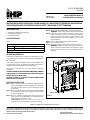
1. Ouvrir le registre inférieur pour accéder à l’indicateur de tem-
pérature (voir Figure 1). Soulever l’indicateur pour le dégager
de la patte de fixation. Retirer les écrous fixant les fils au dos
de l’indicateur.
Étape
2. Retirer le registre de l’ouverture supérieure en le maintenant droit
et en le soulevant jusqu’à ce qu’il se dégage des vis de support
(à l’intérieur du châssis).
Étape
3. Utiliser un tournevis* cruciforme pour retirer les deux (2) vis
situées derrière le tuyau d’évacuation qui maintiennent la ther-
mopile. Retirer la thermopile de l’unité.
*Autre méthode: Utiliser une clé pour retirer l’écrou sur la
thermopile, puis retirer la thermopile de la patte de fixation.
IHP se réserve à tout moment le droit d’apporter sans préavis des changements à la conception, aux matériaux, aux carac-téristiques ou aux prix, ainsi que
de supprimer des optionsde couleurs, de styles et de produits. Pour obtenir de l’information sur les codes des foyers, contacter le distributeur de votre région.
Innovative Hearth Products
1508 Elm Hill Pike, Suite 108 • Nashville, TN 37210
12/08/2015
Imprimé aux États-Unis © 2015 Innovative Hearth Products
P/N 900596-00 Rev. NC 12/2015
REMARQUE : LES SCHÉMAS ET LES ILLUSTRATIONS NE SONT PAS À L’ÉCHELLE
REMPLACEMENT DU MESURE DE
LA TEMPÉRATURE DU CATALYSEUR
Figure 1
Étape
4. Installer la nouvelle thermopile (dans l’ordre inverse de l’étape 3).
REMARQUE : S’assurer que le fil passe du côté gauche de l’unité.
Étape
5. À partir de l’ouverture inférieure, attraper le fil fixé à la ther-
mopile et connecter sa cosse à l’arrière du nouvel indicateur.
Placer le connecteur du fil rouge sur la borne positive (+) et le
connecteur du fil blanc sur la borne négative (-) (à l’arrière du
nouvel indicateur).
Étape
6. Insérer le nouvel indicateur dans la patte de fixation.
Étape
7. Fermer le registre inférieur.
Étape
8. Réinstaller le registre supérieur dans l’ouverture supérieure.
REMARQUE : Maintenir le registre droit et aussi près que pos-
sible de l’intérieur du châssis supérieur, puis abaisser le registre
jusqu’à ce qu’il s’enclenche sur les vis de support à l’intérieur
du châssis.
Thermopile
THERMOPILE
GAUGE
Indicateur de température
-
 1
1
-
 2
2


Astria Fireplaces Villa Vista Instruction Sheet
- Taper
- Instruction Sheet
- Ce manuel convient également à
dans d''autres langues
- English: Astria Fireplaces Villa Vista
Documents connexes
Autres documents
-
Superior SDV35 Manuel utilisateur
-
-
 Lennox Hearth MLBV-35PM Manuel utilisateur
-
Lennox merit plus mpb3530cpm-b Manuel utilisateur
-
Superior Fireplaces BRT40ST Mode d'emploi
-
-
IHP BPZN Manuel utilisateur
