DTS Portfolio Manuel utilisateur
- Catégorie
- Stroboscopes
- Taper
- Manuel utilisateur


2
Le informazioni contenute in questo documento sono state attentamente redatte e
controllate. Tuttavia non è assunta alcuna responsabilità per eventuali inesattezze.
Tutti i diritti sono riservati e questo documento non può essere copiato, fotocopiato,
riprodotto per intero o in parte senza previo consenso scritto della D.T.S .
D.T.S. si riserva il diritto di apportare senza preavviso cambiamenti e modifiche
estetiche , funzionali o di design a ciascun proprio prodotto. D.T.S non assume alcuna
responsabilità sull’uso o sull’applicazione dei prodotti o dei circuiti descritti.
The information contained in this publication has been carefully prepared and
checked. However, no responsibility will be taken for any errors. All rights are
reserved and this document cannot be copied, photocopied or reproduced, in part or
completely, without prior written consent from D.T.S.
D.T.S. reserves the right to make any aesthetic, functional or design modifications to
any of its products without prior notice. D.T.S. assumes no responsibility for the use or
application of the products or circuits described herein.
Les informations contenues dans le présent manuel ont été rédigées et contrôlées
avec le plus grand soin. Nous déclinons toutefois toute responsabilité en cas
d'éventuelles inexactitudes. Tous droits réservés. Ce document ne peut être copié,
photocopié ou reproduit, dans sa totalité ou partiellement, sans le consentement
préalable de D.T.S.
D.T.S. se réserve le droit d'apporter toutes modifications et améliorations esthétiques,
fonctionnelles ou de design, sans préavis, à chacun de ses produits. D.T.S. décline
toute responsabilité sur l'utilisation ou sur l'application des produits ou des circuits
décrits.
Las informaciones contenidas en este documento han sido cuidadosamente
redactadas y controladas. Con todo, no se asume ninguna responsabilidad por
eventuales inexactitudes. Todos los derechos han sido reservados y este documento
no puede ser copiado, fotocopiado o reproducido, total o parcialmente, sin previa
autorización escrita de D.T.S.
D.T.S. se reserva el derecho a aportar sin previo aviso cambios y modificaciones de
carácter estético, funcional o de diseño a cada producto suyo. D.T.S. no se asume
responsabilidad de ningún tipo sobre la utilización o sobre la aplicación de los
productos o de los circuitos descritos.

3
INDEX:
1- SYMBOLS ................................................................................................................. 4
2- GENERAL WARNING .............................................................................................. 4
3- GENERAL WARRANTY CONDITIONS .................................................................... 4
4- TECHNICAL FEATURES ......................................................................................... 5
5- ACCESSORIES ........................................................................................................ 6
6- IMPORTANT SAFETY INFORMATION .................................................................... 7
6.1 Fire prevention...................................................................................................... 7
6.2 Prevention of electric shock .................................................................................. 7
6.3 Safety ................................................................................................................... 7
6.4 Waste Electrical and Electronic Equipment directive ............................................ 7
7- INSTALLATION ........................................................................................................ 8
8- INPUT / OUTPUT CONNECTIONS ........................................................................... 9
9- DMX SIGNAL CONNECTION ................................................................................. 10
9.1 DMX Addresses .................................................................................................. 11
9.2 Selecting the DMX address ................................................................................ 11
10- RDM FUNCTIONS ................................................................................................ 12
11- FIRMWARE UPDATING ....................................................................................... 13
12- DISPLAY FUNCTIONS ......................................................................................... 13
13- MANUAL MODE ................................................................................................... 15
14- ERROR MESSAGES ............................................................................................ 15
15- DMX PROTOCOL ................................................................................................. 16
16- GOBO HOLDER ................................................................................................... 19
17- IRIS ....................................................................................................................... 21

4
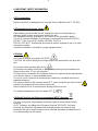
!
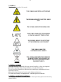
1- SYMBOLS
Graphic symbols used on this manual:
THIS SYMBOL INDICATES A HOT SURFACE
THIS SYMBOL INDICATES ELECTRIC SHOCK
RISK
THIS SYMBOL INDICATES GENERAL RISK
THIS SYMBOL INDICATES THE MAXIMUM
OPERATING AMBIENT TEMPERATURE
THIS SYMBOL MEANS “DO NOT STARE
AT THE OPERATING LIGHT SOURCE”
THIS SYMBOL INDICATES
PHOTOBIOLOGICAL SAFETY
THIS SYMBOL INDICATES THE EUROPEAN
COMMUNITY DIRECTIVE 2012/19/EC ON
WASTE ELECTRICAL AND ELECTRONIC
EQUIPMENT (WEEE)
2- GENERAL WARNING
Read the instruction contained in this user manual carefully, as they give important
information regarding safety during installation, use and maintenance.
The unit is not for residential use and must be installed by a qualified electrician or
experienced person.
Always disconnect the device from the mains before maintenance.
The device must always be equipped with an efficient ground connection.
3- GENERAL WARRANTY CONDITIONS
The unit is guaranteed for 36 months from the date of purchase against manufacturing
material defects.

5
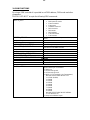
4- TECHNICAL FEATURES
OVERVIEW
PROFILO LED 80 CT is a very compact LED profile spot equipped with an high
efficiency White LED source.
The unit LED’s white color temperature is linearly tunable from 2700K to 6000K;
a must in top level Television and Theatre applications, where a perfectly adjustable
white color temperature is a key requirement.
The unit features an internal four-shutter shaping system, and a 20° to 36° linear
zoom.
DTS product codes:
03.TP033.46 PROFILO LED 80 CT BLACK
03.TP033.03 PROFILO LED 80 CT WHITE
LED Technology
Single high-power White LED with linearly tunable color temperature 2700K – 6000K
Optical group
20°- 36° linear zoom
High definition zoom lens with double optical condenser lens
Control
DMX 512 / RDM
7 DMX channels (Default) or 2 DMX channels
4-digit 7-segment LED display + 4 soft keys
Power supply
Full-range 100-240Vac 50-60 Hz
Consumption: 100W Max
Connections
Power supply: PowerCON In&Out panel connectors
DMX: XLR 5 pins In&Out panel connectors
Operating temperature
-10° / 40°
Weight
5,8 Kg
Certifications
2014/35/UE ; 2014/30/UE
IEC 62471 ; IEC 695-2-1
EN 60598-1 ; EN 62471 ; EN 61347-2-13
EN 60598-2-17 ; EN 55015 EMC ; EN 61347-1

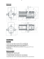
6
DIMENSIONS
5- ACCESSORIES
As standard
1 x PowerCON male cable connector (DTS Code 0520P014)
1 x XLR 5 pins male cable connector (DTS Code 0508B028)
1 x XLR 5 pins female cable connector (DTS Code 0508B027)
4 x Shutter blades (single blade DTS code 02SK0335)
1 x Filterframe black finishing (already installed on the projector) (DTS Code
02M00426.46)
1 x User’s Manual
Optional (on request)
- Iris/diaphram (DTS Code 03.TA223)
- Gobo holder (DTS Code 03.TA224)
- “C” Clamp G50 (Max. Load 10 Kg) (DTS Code 0521A012)
- “C” Clamp G60 (Max. Load 50 Kg) (DTS Code 0521A004)
- Safety cable 3 mm x 60 cm, max capacity load 60 Kg (DTS Code 0521A010)

7
6- IMPORTANT SAFETY INFORMATION
6.1 Fire prevention:
Replace any blown or damaged fuses only with those of identical value: T 2A 250V.
6.2 Prevention from electric shock:
High voltage is present inside the unit. Unplug the unit prior to performing any
operation which involves touching the inside of the unit.
This equipment must be grounded, do not connect to non-grounded supplies.
The use of a thermal magnetic circuit breaker is recommended for each PROFILO
LED 80 CT unit. Use only AC supplies 100-240V 50-60 Hz.
PROFILO LED 80 CT should never be located in position exposed to rain or in areas
of extreme humidity.
A good air ventilation is essential for proper equipment work.
6.3 Safety:
Risk Group 2 product according to EN 62471.
CAUTION. Do not look directly into the light output. May be harmful to the eyes and
skin.
Do not stare at the operating light source.
The luminaire should be positioned so that prolonged staring into the luminaire at a
distance closer than 3.7 m is not expected.
The light source contained in this luminaire shall only be replaced by the manufacturer
or his service agent or a similar qualified person.
The unit is not for household use and must be installed by a qualified electrician or
experienced person.
The external surface of the unit may exeed 60°C; never handle the unit until at least 5
minutes have elapsed since the unit was turned off.
Never install the unit in an enclosed area lacking sufficient air flow.
The ambient temperature should not exeed 40°C.
6.4 Waste Electrical and Electronic equipment (WEEE) directive:
The unit, accessories and packaging should be sorted for environmetal-friendly
recycling.
For EC countries: according to the European Directive 2012/19/EC for Waste
Electrical and Electronic Equipment and its implementation into national right,
luminaires that are no longer usable must be collected separately and disposed of in
an environmentally correct manner.
!

8
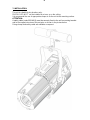
7- INSTALLATION
The unit is suitable for dry locations only.
PROFILO LED 80 CT can be installed on a truss or on the ceiling.
It is recommend the use of appropriate clamps to fix the unit to the mounting surface.
ATTENTION:
A safety cable (code 0521A010) must be securely fixed to the unit’s mounting bracket
and to the support structure of the projector as shown in the picture below.
Fixing clamps and safety cable are available on request.

9
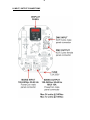
8- INPUT / OUTPUT CONNECTIONS

10
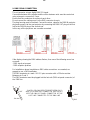
9- DMX SIGNAL CONNECTION:
The unit operates using a digital DMX 512 signal.
Connection between the controller and the unit or between units must be carried out
using a two pair screened ø 0.5 mm.
Ensure that the conductors do not touch each other.
Do not connect the cable ground to the DMX connector chassis.
The plug housing must be isolated. Connect the mixer signal to the DMX IN projector
plug and connect it to the next projector by connecting the DMX OUT plug on the first
unit to the DMX IN plug of the second one.
In this way, all the projectors are cascade connected.
If the display showing the DMX address flashes, then one of the following errors has
occurred:
- DMX signal not present
- DMX reception problem
For Installations where long distance DMX cable connections are needed, we
suggest to use a DMX terminator.
The DMX terminator is a male XLR 3-5 pins connector with a 120 ohm resistor
Between pin 2 and 3.
The DMX terminator must be plugged into the last unit (DMX out panel connector) of
the DMX line.
PLACE A 120 OHM RESISTOR BETWEEN PIN 2
AND 3 OF A MALE XRL CONNECTOR AND PLUG IT
INTO THE DMX OUT PANEL CONNECTOR OF THE
LAST UNIT CONNECTED TO THE DMX LINE
1
2
3
5
4
OUT
120 ohm
PIN 3
PIN 2

11
9.1 DMX addresses
PROFILO LED 80 CT can be controlled with 7 DMX channels (Default) or 2 DMX
channels.
In order to use the unit in 7 DMX channels mode (Default), set the following addresses
on the mixer:
Projector 1 A001
Projector 2 A008 If you want to select the next projector, just add “7”
Projector 3 A015
….. A….
projector 6 A036
9.2 Selecting the DMX address
1) Press the UP-DOWN key until you reach the required DMX address. The numbers
on the display will start to flash (but the new DMX address hasn't yet been set).
2) Press ENTER to confirm your selection. The numbers on the display will stop
flashing and the projector is now controlled by the new DMX address.
TIPS: if you keep pushed the UP or DOWN keys, the channels are calculated more
quickly and you get a faster selection.
2) Press ENTER to confirm your selection. The numbers on the display will stop
flashing and the projector is now controlled by the new DMX address.

12
10- RDM FUNCTIONS
By using a RDM controller it is possible to set DMX address, DMX mode and other
parameters.
PROFILO LED 80 CT accepts the following RDM commands:
DEVICE_INFO
To read the following parameters:
RDM protocol version
Fixture model ID
Fixture type
Software version ID
DMX channels
DMX mode
DMX address
Total sub-fixtures
Total sensors
IDENTIFY_DEVICE
All LED channels ON at max power to identify the
fixture
DMX_START_ADDRESS
To read / set the DMX address
SOFTWARE_VERSION_LABEL
Software version ID
SUPPORTED_PARAMETERS
List of all supported parameters
PARAMETER_DESCRIPTION
Description / details of Manufacturer Specific
parameter as “NO DMX ACTION”
DMX_PERSONALITY
To set the DMX mode
DMX_PERSONALITY_DESCRIPTION
Description / details of the DMX mode
DEVICE_MODEL_DESCRIPTION
Description / details of the Fixture model
MANUFACTURER_LABEL
Producer ID
SENSOR_DEFINITION, SENSOR VALUE
Description / values of sensors
SENSORS
1: LED BOARD TEMPERATURE
LED temperature
2: DRIVER BOARD TEMPERATURE
LED Driver board temperature
RDM MANUFACTURER-SPECIFIC PIDs
NO DMX ACTION
To set the desired fixture’s behavior in case DMX
signal is missing or not available.
1 = Black-out
2 = All channels @ 60%
3 = All channels @ 100%
4 = White CCT (Correlated Color Temperature):
NO DMX SELECTABLE WHITE CCT
1 = 2700K (Default)
2 = 3000K
3 = 3200K
4 = 3500K
5 = 4000K
6 = 4500K
7 = 5000K
8 = 5600K
9 = 6000K
NO DMX SELECTABLE WHITE INTENS.
0 ÷ 255 (Default = 0)
5 = Keep last valid DMX signal

13
11- FIRMWARE UPDATING
To update the software version of the PROFILO LED 80 CT you need:
- DTS RED BOX interface (DTS Code 03.LA.008).
- USB-DMX Driver for the DTS RED BOX interface.
- “DTS Firmware Upgrade Utility v.2.02” program installed on PC.
- Latest firmware release available for PROFILO LED 80 CT unit.
Updating the software version.
Please follow the procedure below to perform the update:
1. Install the DTS RED BOX USB-DMX driver on the PC you will use to update the unit
software.
2. Connect the DTS RED BOX interface to a spare USB port on the PC (be sure that
internal switch on DTS RED BOX is set to COM).
3. Connect the unit DMX input to the DTS RED BOX DMX output with a standard DMX
cable and turn ON the unit.
4. Send the new software version into the unit by using “DTS Firmware upgrade
Utility v.2.02” program. At the end of the procedure, the unit will reset.
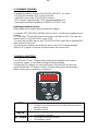
12- DISPLAY FUNCTIONS
The PROFILO LED 80 CT display panel shows all the available control menus.
Using these options, it is possible to change the fixture’s setting.
Changing the DTS settings can vary the functions of the unit so that it does not
respond to the DMX 512 used to control it. Carefully follow the instructions below
before carrying out any variations or selections.
MENU
To access the control menus in the display panel.
To return to the previous level in the menu structure without
making a change.
To exit the menus.
ENTER
To select any required menu.
To confirm any changes.
UP / DOWN
To navigate the menus structure.
To change any value.

14
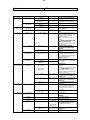
Firmware release
1.00
MAIN MENU
LEVEL 1
LEVEL 2
LEVEL 3
FUNCTION
Display normal orientation for
floor mounting position (Default)
Display inverted orientation for
suspended mounting position
Display always ON (Default)
Display goes OFF after 10 seconds
Allows to select 7 DMX channels
mode (Default)
Allows to select 2 DMX channels
mode
Allows to select the value of the
delay (in milliseconds) for Dimmer
channel reaction to DMX or
Program variation.
Off = Instant response to DMX
variation.
4 = 100 ms Smooth response to
DMX variation (Default)
20 = 500 ms Smooth response to
DMX variation.
Allows to select Quadratic
current for linear light output
(Default)
Allows to select Linear current
output
Allows to adjust the PWM
frequency value (Hz) in order to
reduce flickering in the process of
your camera recordings.
Default = 610 Hz
Allows to increase the LED’s
current from 1470mA to 2100mA
per channel
Default = ON
Automatic mode without DMX
controller.
9 White color temperature selection
from 2700K (Default) to 6000K
as on DMX channel 6 (CCT).
In Auto mode the unit do generate
DMX for slave units.
Dimmer level selectable by user as
on DMX channel 4 (DIMMER)
Default = 255
Shutter level selectable by user as
on DMX channel 3 (SHUTTER)
Default = 0
Esc from automatic mode menu
Slave mode.
The unit is forced to DMX address 1
and 7 DMX channels mode
receiving signal from the unit set in
Auto mode.
Esc from slave mode
No DMX action.
Keep last valid DMX signal
(Default)
All channels @ 60%
All channels @ 100%
9 White color temperature selection
from 2700K (Default) to 6000K as
on DMX channel 6 (CCT)
Dimmer level selectable for White
Default = 255
Black-out

15
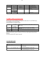
MAIN MENU
LEVEL 1
LEVEL 2
LEVEL 3
FUNCTION
To restore default settings
LED temperature monitoring
LED Driver board temperature
monitoring
Shows the total unit life time and
the Warm White / Cold White LEDs
life time
Software version
13- MANUAL MODE (not yet implemented)
Manual mode can be activated by pressing at the same time ‘UP’ and ‘DOWN’ keys
on unit display for 3 seconds (A001).
In Manual mode it is possible to select:
9 White color temperature selection from 2700K to 6000K as on DMX channel 6
(CCT).
Default = 2700K
Dimmer level selectable by user as on DMX channel 4 (DIMMER)
Default = 255
Shutter level selectable by user as on DMX channel 3 (SHUTTER)
Default = 15
Esc from Manual mode
When Manual mode is active, unit switch OFF/ON cycle will maintain Manual Mode
selection.
In Manual mode the DMX signal is ignored.
14- ERROR MESSAGES
ERROR SHOWED ON DISPLAY
APPEARS WHEN
LED thermal sensor damaged (open or in
short circuit).
Unit immediately goes in black-out.
LED temperature detected over 100°C.
Unit immediately goes in black-out.

16
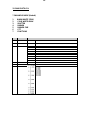
15- DMX PROTOCOL
7 CHANNELS MODE (Default)
1 WARM WHITE 2700K
2 COLD WHITE 6000K
3 SHUTTER
4 DIMMER
5 DIMMER FINE
6 CCT
7 FUNCTIONS
Ch
Name
DMX levels
1
WARM WHITE 2700K
0..255
Proportional color from min to max
2
COLD WHITE 6000K
0..255
Proportional color from min to max
3
SHUTTER
0..9
Black-out
10..19
Open
20..29
Black-out
30..119
Strobe (da 3,27 s a 30 ms)
120..149
Pulse up (da 42,6 s a 120 ms)
150..179
Pulse down (da 42,6 s a 120 ms)
180..204
Random strobe (Warm White, Cold White, Dimmer, Dimmer Fine active)
205..229
Independent random strobe (Dimmer, Dimmer Fine active)
230..255
Open
4
DIMMER
0..255
Proportional dimmer from min to max
5
DIMMER FINE
0..255
Proportional dimmer from min to max
6
CCT
Linear color temperature correction from 2700K to 6000K.
Relevant CCT (Correlated Color Temperature) values:
11 = 2700K
54 = 3000K
83 = 3200K
126 = 3500K
169 = 4000K
198 = 4500K
226 = 5000K
241 = 5600K
255 = 6000K

17
Ch
Name
DMX levels
7
FUNCTIONS (staying
on desired option for
5 seconds)
0..14
No function
15..24
SMOOTH OFF
25..26
SMOOTH 1 (25 ms)
27..28
SMOOTH 2 (50 ms)
29..30
SMOOTH 3 (75 ms)
31..32
SMOOTH 4 (100 ms) (DEFAULT)
33..34
SMOOTH 5 (125 ms)
35..36
SMOOTH 6 (150 ms)
37..38
SMOOTH 7 (175 ms)
39..40
SMOOTH 8 (200 ms)
41..42
SMOOTH 9 (225 ms)
43..44
SMOOTH 10 (250 ms)
45..46
SMOOTH 11 (275 ms)
47..48
SMOOTH 12 (300 ms)
49..50
SMOOTH 13 (325 ms)
51..52
SMOOTH 14 (350 ms)
53..54
SMOOTH 15 (375 ms)
55..56
SMOOTH 16 (400 ms)
57..58
SMOOTH 17 (425 ms)
59..60
SMOOTH 18 (450 ms)
61..62
SMOOTH 19 (475 ms)
63..64
SMOOTH 20 (500 ms)
65..74
GAMMA CORRECTION () QUADRATIC (DEFAULT)
75..84
GAMMA CORRECTION () LINEAR
85..104
OUTPUT FREQUENCY 610 Hz (DEFAULT)
105
OUTPUT FREQUENCY 800 Hz
106
OUTPUT FREQUENCY 1000 Hz
107
OUTPUT FREQUENCY 1500 Hz
108
OUTPUT FREQUENCY 2000 Hz
109
OUTPUT FREQUENCY 2500 Hz
110
OUTPUT FREQUENCY 3000 Hz
111
OUTPUT FREQUENCY 3500 Hz
112
OUTPUT FREQUENCY 4000 Hz
113
OUTPUT FREQUENCY 4500 Hz
114
OUTPUT FREQUENCY 5000 Hz
115
OUTPUT FREQUENCY 5500 Hz
116
OUTPUT FREQUENCY 6000 Hz
117
OUTPUT FREQUENCY 6500 Hz
118
OUTPUT FREQUENCY 7000 Hz
119
OUTPUT FREQUENCY 7500 Hz
120
OUTPUT FREQUENCY 8000 Hz
121
OUTPUT FREQUENCY 8500 Hz
122
OUTPUT FREQUENCY 9000 Hz
123
OUTPUT FREQUENCY 9500 Hz
124
OUTPUT FREQUENCY 10000 Hz
125
OUTPUT FREQUENCY 11000 Hz
126
OUTPUT FREQUENCY 12000 Hz
127
OUTPUT FREQUENCY 13000 Hz
128
OUTPUT FREQUENCY 14000 Hz
129
OUTPUT FREQUENCY 15000 Hz
130
OUTPUT FREQUENCY 16000 Hz
131
OUTPUT FREQUENCY 17000 Hz
132
OUTPUT FREQUENCY 18000 Hz
133
OUTPUT FREQUENCY 19000 Hz
134
OUTPUT FREQUENCY 20000 Hz
135..144
BOOST ON (DEFAULT)
145..154
BOOST OFF
155..164
DISPLAY STAND-BY OFF (DEFAULT)
165..174
DISPLAY STAND-BY ON

18
Ch
Name
DMX levels
175..176
NO DMX ACTION – KEEP LAST DMX (DEFAULT)
177..178
NO DMX ACTION – Black-out
179..180
NO DMX ACTION – All channels @ 100%
181..182
NO DMX ACTION – All channels @ 60%
183..184
NO DMX ACTION – 2700K..6000K (active CCT as per display menu > NDMX > WHIT or via RDM Custom
PIDs (Default = 2700K)
185..194
RESERVED
195..204
RESERVED
205..214
RESERVED
215..224
RESERVED
225..234
RESERVED
235..244
RESERVED
245..255
RESERVED
2 CHANNELS MODE
1 WARM WHITE 2700K
2 COLD WHITE 6000K
Ch
Name
DMX levels
1
WARM WHITE 2700K
0..255
Proportional color from min to max
2
COLD WHITE 6000K
0..255
Proportional color from min to max

19
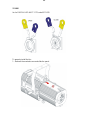
16- GOBO HOLDER
Gobo Holder for PROFILO LED 80 CT: DTS code 03.TA224
(Metal / Glass Gobo not included).
Gobo dimensions:
Ø external = 66 mm
Ø of image = 48 mm
Thickness = from 0.2 to 3 mm
How to fix the Gobo on Gobo Holder:
1 - Loose the marked screws fixing each metal plate.
2 - Put in place the Gobo and tighten again the screws.
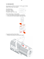
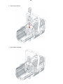
To properly install the Gobo Holder:
1 - Remove the marked screw and slide the panel.

20
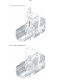
2 - Put in place the Gobo Holder.
3 - Gobo Holder properly inserted.
La page est en cours de chargement...
La page est en cours de chargement...
La page est en cours de chargement...
La page est en cours de chargement...
-
 1
1
-
 2
2
-
 3
3
-
 4
4
-
 5
5
-
 6
6
-
 7
7
-
 8
8
-
 9
9
-
 10
10
-
 11
11
-
 12
12
-
 13
13
-
 14
14
-
 15
15
-
 16
16
-
 17
17
-
 18
18
-
 19
19
-
 20
20
-
 21
21
-
 22
22
-
 23
23
-
 24
24


DTS Portfolio Manuel utilisateur
- Catégorie
- Stroboscopes
- Taper
- Manuel utilisateur
dans d''autres langues
- italiano: DTS Portfolio Manuale utente
- English: DTS Portfolio User manual
Documents connexes


Autres documents
-
 hykolity LED Guide d'installation
-
Chauvet Colorado Guide de référence
-
 Robert Juliat SULLY 315L 4C Guide de démarrage rapide
-
Martin ERA 400 Performance WRM Manuel utilisateur
-
OXO PixyLine 150 Manuel utilisateur
-
Chauvet OVATION Guide de référence
-
-
-
-
Evolite Evo Spot 60-CR Manuel utilisateur

