England's Stove Works 55-TRP22 Installation & Operation Manual
- Catégorie
- Cheminées
- Taper
- Installation & Operation Manual
Ce manuel convient également à

INSTALLATION & OPERATION MANUAL
Manufactured By:
England’s Stove Works, Inc.
PO Box 206
Monroe, VA 24574
9/7/2012
SAVE THESE
INSTRUCTIONS
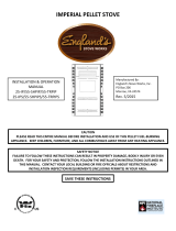
Pellet Stove
MODELS 25-PDV / 55-SHP22 / 55-TRP22

Introduction
Precautionary Statements ......................... 3
Message from Us ..................................... 4
Read Before Getting Started .................... 5
Important Information .............................. 6
Installation
Unit Preparation ....................................... 7
Proper Baffle Placement .......................... 8
Flue System ............................................. 9
Pellet Vent Pipe ......................... 9
Through the Wall ....................... 9
Through the Ceiling ................. 10
Existing Flue System ............... 10
Outside Air .............................. 10
Mobile Home Installation ...................... 10
Installation Diagrams ............................. 11
Floor and Wall Protection ...................... 11
Vent Termination Clearances ................ 12
OperatingInstructions
Explanation ............................................ 13
Start-Up Procedure ................................ 13
E-Codes.................................................. 14
Shut-Down Procedure ............................ 14
Daily Operation...................................... 15
Refueling ................................. 15
Power Outage .......................... 15
Fuel Outage ............................. 15
Combustion Blower Failure ..... 15
AshRemoval/Maintenance
Daily ...................................................... 16
Semi-Weekly ......................................... 16
Monthly.................................................. 17
Annual ................................................... 17
Rear Panel Removal ............................... 18
Auger Motors ......................................... 18
Auger Bearings & Shafts ....................... 18
Hopper Lid Switch ................................. 18
Convection Blower ................................ 19
Combustion Blower .............................. 19
Vacuum Switch ..................................... 19
Vacuum Switch Port ............................. 19
Gaskets .................................................. 20
Finish ..................................................... 20
Glass ...................................................... 20
Control Board ........................................ 21
Wiring Diagram .................................... 22
Hopper Lid Latches ............................... 23
Accessory Items .................................... 24
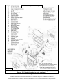
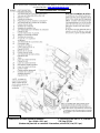
IllustratedPartsDetail
Parts List ............................................... 25
Exploded Parts Diagram ....................... 26
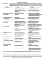
TroubleshootingGuide
Troubleshooting .................................... 27
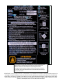
Warranty
Serial Tag Sample ................................. 28
Warranty Details ................................... 29
Warranty Registration Form .................. 31
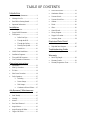
TABLE OF CONTENTS

INSTALLATION & OPERATION MANUAL
MODEL NUMBERS: 25-PDV 55-SHP22 55-TRP22
Thank you for purchasing this product from a fine line of heating equipment.
We wish you many years of safe heating pleasure with your new heating appliance.
Save These Instructions.
IMPORTANT: IF YOU HAVE A PROBLEM WITH THIS UNIT DO NOT RETURN IT TO
THE DEALER. CONTACT TECHNICAL SUPPORT @ 1-800-245-6489.
Please Note the Following Precautionary Statements:
NOTE: WE DO NOT RECOMMEND PELLET STOVES AS YOUR ONLY SOURCE OF HEAT.
CAUTION: Please read this entire manual before installation and use of this pellet fuel
burning room heater.
Keep children, furniture, fixtures, and all combustible materials away from
any heating appliance. Refer to this owner’s manual for all clearances to
combustible materials.
WARNING: USE OF OUTSIDE AIR IS MANDATORY WITH THIS UNIT.
DO NOT OPERATE UNIT WITH HOPPER OPEN. LID MUST BE SHUT AND TIGHTLY SECURED.
DO NOT OPERATE WITH DOOR OPEN
SAFETY NOTICE
FAILURE TO FOLLOW THESE INSTRUCTIONS COULD RESULT IN PROPERTY DAMAGE,
BODILY INJURY OR EVEN DEATH. FOR YOUR SAFETY AND PROTECTION, FOLLOW ALL
THE INSTALLATION INSTRUCTIONS. CONTACT YOUR LOCAL BUILDING OR FIRE
OFFICIALS FOR RESTRICTIONS AND INSTALLATION INSPECTION REQUIREMENTS
(INCLUDING PERMITS) IN YOUR AREA.
Questions? Need Parts or Options? www.englanderstoves.com
England’s Stove Works highly recommends the use of smoke detectors and
Carbon Monoxide detectors with any hearth product, including this unit. Follow all
manufacturer’s instructions when using smoke or Carbon Monoxide detectors.
Mobile Home Use:
These freestanding pellet units are approved for mobile home or doublewide installation with
outside combustion air hook-up. See “Flue System” section of manual.
Mobile home installation should be in accordance with the Manufactured Home and Safety
Standard (HUD), CFR 3280, Part 24.
WARNING
: Do Not Install in Sleeping Room
CAUTION
: The structural integrity of the mobile home floor, wall and ceiling/roof must
be
m
a
in
ta
in
ed
.

IMPORTANT! READ AND FOLLOW ALL INSTALLATION AND MAINTENANCE INSTRUCTIONS, INCLUDING
CLEANING THE UNIT AS SPECIFIED, AND REPLACING GASKETS ANNUALLY, AND PARTS AS NEEDED.
ENGLAND’S STOVE WORKS IS NOT RESPONSIBLE FOR ANY DAMAGE OR INJURY INCURRED DUE TO NEGLECT, OR
DUE TO UNSAFE INSTALLATION OR USAGE OF THIS PRODUCT. CALL TECHNICAL SUPPORT WITH QUESTIONS.
4
A letter from our Technical Support department:
Thank you
for purchasing this fine product from England’s Stove Works!
England's Stove Works was started, and is still owned by, a family that
believes strongly in a "Do It Yourself" spirit – that’s one reason you found
this product at your favorite “Do It Yourself” store.
We intentionally design and build our stoves so that any homeowner can
maintain his or her unit with basic tools, and we're always more than
happy to show you how to do the job as easily and as inexpensively as
possible.
From our free,
downloadable service sheets; to our Pellet Service Video;
to our new "wizard-style," click-through Troubleshooting guide on our
web site, we have always tried to help our customers stay "heat-ready,"
especially when oil and electricity prices continue to skyrocket.
Please look at our vast Help section on our web site and call our Technical
Support department at (800) 245-6489 if you need any help with your unit.
We are nearly always
able to help “walk you through” any repairs,
problems or questions you may have.
PLEASE NOTE
: While information obtained on our web site and through
our 800 number is always free of charge, there will be a service charge
incurred with any “on-site” repairs or maintenance that we may arrange.
Wishing you years of efficient, quality and “comfy” heating,
England’s Stove Works
Technical Support Department
www.englanderstoves.com
(800) 245-6489
IF YOU HAVE A PROBLEM WITH THIS UNIT DO NOT RETURN IT TO THE DEALER.
CONTACT TECHNICAL SUPPORT at 1 (800) 245-6489.

IMPORTANT! READ AND FOLLOW ALL INSTALLATION AND MAINTENANCE INSTRUCTIONS, INCLUDING
CLEANING THE UNIT AS SPECIFIED, AND REPLACING GASKETS ANNUALLY, AND PARTS AS NEEDED.
ENGLAND’S STOVE WORKS IS NOT RESPONSIBLE FOR ANY DAMAGE OR INJURY INCURRED DUE TO NEGLECT, OR
DUE TO UNSAFE INSTALLATION OR USAGE OF THIS PRODUCT. CALL TECHNICAL SUPPORT WITH QUESTIONS.
5
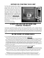
BEFORE RE-STARTING YOUR UNIT
Every time before pressing “ON” to start your
unit – Be sure to remove all ashes (burnt or
partially burnt) from your burn pot area!
Wearing protective gloves and with the unit
cool, remove the Wear Plate and dump the
ashes, ensuring that the air holes are clear
from debris. Also be sure to follow all other
maintenance instructions as outlined in your
Owner’s Manual and the Instructional DVD
included with the unit. Failure to remove
ashes from this area before each burn
can
cause smoke-back and serious damage to
your stove, and can void your warranty. We
will not be held responsible for poorly
maintained units, including excess ash in the
burn pot area.
Burn Safe and Burn Clean –
Clean the burn pot area daily!
A NOTE ON COLD AIR RETURNS AND
CENTRAL FURNACES
Some homes, including the modern, air-tight homes that are well-insulated, create a negative draft that
could cause smoke to be released from your unit, especially if it is too close to your home’s Central
Furnace. If you install your stove in the same room as the Cold Air Return from your home’s Central
Furnace, you must place your stove at least 20 feet (20’) from the Cold Air Return. We recommend you
open an outside window slightly, and never close the door that leads from this room to the rest of your
home.
IN THE EVENT OF SMOKE-BACK
1. If you see smoke coming out of your unit into the room due to a power failure,
DO NOT OPEN THE HOPPER OR DOOR TO YOUR UNIT!! Remain calm
.
Open the nearest outside door and windows and wait for all signs of smoke to clear (at least one
hour, although the smoke should dissipate quickly once the door and windows are opened). When
power is restored, press the ON button to restart your unit, and let the unit run for at least 30 minutes.
-- If you see any further signs of smoke-back, press the OFF button and call Technical Support at (800)
245-6489 before restarting your unit, as damage could have occurred due to the power failure.
-- If you see no more signs of smoke-back, press the OFF button and wait for your unit to completely
shut down and cool down, then clean the burn pot area before restarting your unit (see “Before Re-
Starting Your Unit,” above).
2. If you see smoke coming out of your unit into the room and the power has not failed,
DO NOT OPEN THE HOPPER OR DOOR TO YOUR UNIT!! Remain calm
.
Immediately press the OFF button, open the nearest outside door and windows and wait for all signs
of smoke to clear (at least one hour, although the smoke should dissipate quickly once the door and
windows are opened). Do NOT restart your unit before calling Technical Support at (800) 245-6489.
Please call Technical Support at (800) 245-6489 with any questions. England’s Stove Works, Inc.

IMPORTANT! READ AND FOLLOW ALL INSTALLATION AND MAINTENANCE INSTRUCTIONS, INCLUDING
CLEANING THE UNIT AS SPECIFIED, AND REPLACING GASKETS ANNUALLY, AND PARTS AS NEEDED.
ENGLAND’S STOVE WORKS IS NOT RESPONSIBLE FOR ANY DAMAGE OR INJURY INCURRED DUE TO NEGLECT, OR
DUE TO UNSAFE INSTALLATION OR USAGE OF THIS PRODUCT. CALL TECHNICAL SUPPORT WITH QUESTIONS.
6
IMPORTANT INFORMATION
1. Check local installation codes for your area. Call your Homeowner’s Insurance representative for
inspection of your stove’s installation.
2. Read and comply with the instructions in this manual.
3. This unit should be tested (dry run) before loading pellets for 20 minutes. The stove should
automatically shut itself off after the 20-minute dry run.
4. Your stove is designed to burn Wood Pellets only. Burning pea coal, cherry pits, or anything
other than wood pellets will void your warranty. Pellets with high ash content will burn dirty and
require the unit to be cleaned more often. This unit is designed for use with ¼” diameter pellet
fuel. Using pellets longer than 2” can bind the auger and require frequent manual removal.
5. Be sure your pellets are not damp or wet. Keep sawdust out of the unit.
6. Use three-inch (3”) U.L.-approved (ULC if Canada) PELLET VENT TWIST-LOCK PIPE when
installing this stove and follow the manufacturer’s specifications for installation and clearances
(we
highly recommend Dura-Vent pellet twist-lock pipe: AC-3000 kit, AC-33000 if Canada). For
installations over 4000 ft. above sea level the exhaust should be vented with 4"pellet vent pipe
(AC-3100 kit, AC-33100 if Canada). Even though this pipe interlocks, it is a good idea to seal all
connections with high temperature silicone (AC-RTV3). Use at least three screws to secure the
pipe to this unit’s exhaust blower. Also, if you do not use U.L.-approved twist-lock pellet pipe, be
sure to use U.L.-approved Pellet Vent pipe, and fasten each joint of the pipe with at least three
screws (ULC-approved if Canada).
Outside combustion air is mandatory for these units to work properly. Make this connection using a 1
7
/
8
”
I.D. metal pipe (steel, aluminum or copper) and coupler. Be sure to secure the pipe to the unit with a clamp
or aluminum tape. The outside end should be covered (screened) to prevent any foreign matter from
entering the system.
Try to keep the number of bends in this pipe to a minimum. Our Part Number PU-OAK (Outside Air Kit with
flex pipe) can be used.
NOTE
: If an older unit, measure the opening to determine what size pipe to use.
NOTE: If the total run of the intake air connection exceeds 6’, use 3” metal pipe and coupler instead.
7. Regularly inspect the burn pot area and, if any crust forms, remove it with a poker.
8. The ash in the burn pot should be removed regularly, depending on your burn rate. The area to
the right and left of the burn pot is for ash storage; keep the air holes in the burn pot clean for a
more efficient burn. Check your exhaust system frequently. Refer to “Ash Removal and Disposal”
section.
9. Keep pellets and all other combustible materials a safe distance from the unit.
10. This unit will require floor protection if installed on a combustible surface. The minimum floor
protector for the 25-PDV should give at least one inch (1”) of protection at the rear, four inches (4”)
on each side, and six inches (6”) minimum in the front of the unit.
11. Horizontal runs should not exceed four feet (4’) with a maximum vertical flue height of thirty five
feet (35’). At fifteen feet (15’), the pipe should be increased to four inch (4”) pellet vent pipe.
12. This unit should be turned off and allowed to cool prior to cleaning. Any ashes should be kept in
an airtight metal container and not disposed of until they are completely cooled.
13. Read the instructions thoroughly, including instructions concerning the digital control board, and
save them for future reference.

IMPORTANT! READ AND FOLLOW ALL INSTALLATION AND MAINTENANCE INSTRUCTIONS, INCLUDING
CLEANING THE UNIT AS SPECIFIED, AND REPLACING GASKETS ANNUALLY, AND PARTS AS NEEDED.
ENGLAND’S STOVE WORKS IS NOT RESPONSIBLE FOR ANY DAMAGE OR INJURY INCURRED DUE TO NEGLECT, OR
DUE TO UNSAFE INSTALLATION OR USAGE OF THIS PRODUCT. CALL TECHNICAL SUPPORT WITH QUESTIONS.
7
14. Do not allow paint, chemicals or construction dust on or near your unit. Do not allow liquid or ANY
foreign materials on or inside your unit. Shut your unit down and cover it when painting,
construction or similar activity is taking place. Wipe and clean your unit after any construction is
done in your home, or if any foreign material gets on or inside your unit. You may also need to
remove the rear and side cover plates to your unit (unplug unit first) and vacuum and clean the
motors and inside of your unit.
15. Improper gasket maintenance, including failure to replace gaskets, can cause air leaks resulting in
smoke-backs. See Gaskets section of this manual, page 20.
16. Remember that, as with any appliance, there is user responsibility involved, including installation,
operation and maintenance of this product. Be sure to check local codes, and call Technical
Support at (800) 245-6489 if you have any questions.
17. Be sure to follow the directions of all manufacturers of third party products that you use,
including exhaust pipe, etc. Never use gasoline, lantern fuel, charcoal lighter fluid, diesel
fuel or any other flammable liquid to start the fire. If you manually start your unit,
recommended fire starter materials are: Wax-impregnated wood chips, cardboard cubes or
firestarter chips designed for pellet stoves (see section on Manually Starting Unit). Follow
any manufacturer’s directions for these products, and NEVER place any firestarter on any
hot surface or hot coals. Never apply any firestarter products of any kind to a hot surface
or hot coals.
18. Basement Installation: We recommend basement installation be performed only by a
professional installer. For basement installations, a 3” (three inch) pipe and coupler must be used
for Outside Combustion Air, and a minimum clearance of 3’ (three feet) must be maintained from
the ground to the pellet vent exhaust pipe outside the dwelling. Keep in mind that each elbow
used reduces draft by 15%; it is good practice to add 3’ (three feet) of vertical rise for each elbow
used. Example: After the 2
nd
elbow used, have 6’ (six feet) of vertical rise before terminating your
vent pipe.
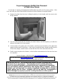
UNIT PREPARATION
1. Attach the spring handle to the door by turning it counterclockwise.
Important: Also check hopper latches – must be tight so that the top is sealed to prevent
back-burn.
2. Test your 110-volt outlet for current and then plug in the unit. (We highly recommend a surge
protector for our pellet unit, as the control panel is electronic).
3. It is important to note that this stove is equipped with a dual auger system. The top auger runs
intermittently and drops pellets to the bottom auger; the bottom auger runs constantly and simply
pushes the pellets forward to the burn pot. The control board (“Heat Range”) setting determines
the top auger feed rate.
4. The stove has a digital read-out control board and is started by pressing the “ON” touch pad. This
will start the upper auger, bottom auger and exhaust blower. The room air blower will start later as
the stove reaches the pre-set blower temperature (see “Control Board” section for further
explanation).
5. Check to be sure both augers and the exhaust blower are operating before connecting the unit to
the flue system. Be sure to “dry run” your unit for 20 minutes before connecting it to the flue (it
should stop automatically after 20 minutes).

IMPORTANT! READ AND FOLLOW ALL INSTALLATION AND MAINTENANCE INSTRUCTIONS, INCLUDING
CLEANING THE UNIT AS SPECIFIED, AND REPLACING GASKETS ANNUALLY, AND PARTS AS NEEDED.
ENGLAND’S STOVE WORKS IS NOT RESPONSIBLE FOR ANY DAMAGE OR INJURY INCURRED DUE TO NEGLECT, OR
DUE TO UNSAFE INSTALLATION OR USAGE OF THIS PRODUCT. CALL TECHNICAL SUPPORT WITH QUESTIONS.
8
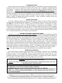
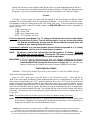
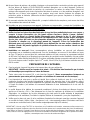
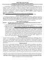
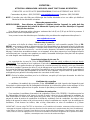
Proper Impingement (Baffle) Plate Placement
in Pellet Stove Firebox
Occasionally in shipping, the impingement (baffle) plate may shift out of its proper position. If this
is the case with your stove, follow these instructions to return the plate to its proper position.
1. Remove the plate from the stove, holding the plate by its tab handle, with the cutout notch
facing upwards.
2. Turn the notched end into the doorway (as shown above), and lift the plate up to allow the
bottom of the plate to fit in the doorway.
3. Let the bottom of the plate rest on the firebox, and then push the bottom of the plate flush
against the back wall of the firebox. At this point, the plate will lean forward (toward the front
of the stove) slightly, and will come in contact with the front of the stove above the door.
4. Finally, center the plate on the firebox, so that it will be centered above the fire when the stove
is in operation.
Technical Support: (800) 245-6489 www.englanderstoves.com
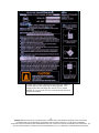
IMPORTANT NOTICE: This unit must be properly installed to prevent the possibility
of a house fire or “smoke-back.” The instructions must be strictly adhered to.
Do not use makeshift methods or material which may compromise the installation.
Your unit requires periodic maintenance and cleaning (refer to manual). Failure to
maintain your unit may lead to a variety of problems, including but not limited to
smoke spillage into the home. England’s will not be liable for consequential or
indirect damages to property or persons resulting from the use of this product.
Visit our web site at www.englanderstoves.com for helpful information, frequently asked
questions, parts/accessory orders and more!

IMPORTANT! READ AND FOLLOW ALL INSTALLATION AND MAINTENANCE INSTRUCTIONS, INCLUDING
CLEANING THE UNIT AS SPECIFIED, AND REPLACING GASKETS ANNUALLY, AND PARTS AS NEEDED.
ENGLAND’S STOVE WORKS IS NOT RESPONSIBLE FOR ANY DAMAGE OR INJURY INCURRED DUE TO NEGLECT, OR
DUE TO UNSAFE INSTALLATION OR USAGE OF THIS PRODUCT. CALL TECHNICAL SUPPORT WITH QUESTIONS.
9
FLUE SYSTEM
Caution: Follow the pipe manufacturer’s installation instructions and directions for passing
through combustible walls and ceilings.
Be sure to check local codes in your area.
NOTE: See the installation drawing later in this manual (Illustration 1).
This unit is equipped with a negative draft system that pulls combustion air through the burn pot
and pushes the exhaust air out of the dwelling. If this unit is connected to the flue system other than
the way explained in this manual, it will not function properly.
For any of these installations, keep in mind that each elbow used reduces draft by 15%; it is good
practice to add 3’ (three feet) of vertical rise for each elbow used. Example: After the 2
nd
elbow used,
have 6’ (six feet) of vertical rise before terminating your vent pipe.
Pellet Vent Pipe
The UL approved (ULC if Canada) pellet vent pipe that we recommend is a twist lock system;
however, it is still recommended that high temperature silicone (AC-RTV3) be used at each joint.
England’s Stove Works recommends the use of Dura-Vent twist-lock pipe (AC-3000 kit, AC-33000
if Canada; if you use other pipe, consult your local building codes and/or building inspectors, and
secure each joint with at least three screws—see Important Information, above). Do not use “B” vent
gas pipe or galvanized pipe with this unit. The pellet pipe is designed to disassemble for cleaning and
should be checked several times during the burning season — pellet vent pipe is not furnished with
the unit and must be purchased separately. For installations over 4000 ft. above sea level the
exhaust should be vented with 4"pellet vent pipe (AC-3100 kit, AC-33100 if Canada). Do not install
a flue damper of any kind in this system, and do not connect this unit to a flue system serving
another heating appliance.
Through the Wall
To vent the unit through the wall, connect the pipe adapter to the exhaust motor adapter. If the
exhaust adapter is at least eighteen inches (18”) above ground level, a straight section of pellet pipe
can be used to initially pass through the wall (see Illustration 1). Your dealer or our factory should be
able to provide you with a kit that will handle most of this installation, which will include a wall thimble
that will allow the proper clearances through a combustible wall. Once outside the structure, a three-
inch (3”) clearance should be maintained to the outside wall and a clean out tee should be placed on
the pipe that extends through the wall. We recommend a minimum of three feet (3’) of vertical pipe
with a 90-degree turn away from the house. At this point, a one-foot (1’) section and horizontal cap will
complete the installation (see Illustration 1).
A wall strap should be placed just below the last 90-degree section to make the system more
stable. If you live in an area that has heavy snowfall, it is recommended the installation be taller than
three feet (3’) to get above the snowdrift line.
The same type installation can be used if your stove is below ground level by adding the clean-out
section and vertical pipe inside until ground level is reached. However, we recommend basement
installation be performed only by a professional installer. For basement installations, a 3” (three inch)
pipe and coupler must be used for Outside Combustion Air, and a minimum clearance of 3’ (three
feet) must be maintained outside the dwelling from the ground to the Pellet Vent Exhaust Pipe.
The through-the-wall installation is the least expensive and simplest installation. In a through-the-
wall installation you should be mindful of the snowdrift line, as well as dead grass and leaves. We
recommend a three foot (3’) minimum vertical rise on the inside or the outside of the dwelling.

IMPORTANT! READ AND FOLLOW ALL INSTALLATION AND MAINTENANCE INSTRUCTIONS, INCLUDING
CLEANING THE UNIT AS SPECIFIED, AND REPLACING GASKETS ANNUALLY, AND PARTS AS NEEDED.
ENGLAND’S STOVE WORKS IS NOT RESPONSIBLE FOR ANY DAMAGE OR INJURY INCURRED DUE TO NEGLECT, OR
DUE TO UNSAFE INSTALLATION OR USAGE OF THIS PRODUCT. CALL TECHNICAL SUPPORT WITH QUESTIONS.
10
Through the Ceiling
When venting the stove through the ceiling, the pipe is connected the same as through the wall,
except the clean out tee is always on the inside of the house, and a 3” adapter is added before the
clean-out tee. You must use the proper ceiling support flanges and roof flashing supplied by the pipe
manufacturer -- follow the pipe manufacturer’s directions and Illustration 1 in this manual.
It is
important to note that if your vertical runs of pipe are more than fifteen feet (15’), the pellet vent pipe
should be increased to four inches (4”) in diameter. Do not exceed four feet (4’) of pipe on a horizontal
run, and do attempt to use the least number of elbows in the flue system. If an offset is used it is
better to install a 45-degree elbow whenever possible. Please remember, installing elbows may
inhibit your draft by up to 15% per elbow.
Existing Flue System
If you are replacing a wood stove with a pellet unit the chimney or pipe should be thoroughly
cleaned before proceeding with the installation. If connecting this stove to a factory built chimney, it
may ONLY be a 6” flue, UL103 HT venting system (ULC S629 if Canada). Connection to any other
factory built chimney may result in a poorly operating or dangerous stove installation. When
connecting to an existing masonry chimney, the cross-sectional area of the flue must be considered.
A chimney with a flue larger than 6” round (28.27 sq. in.) may require relining with an approved pellet
stove chimney lining system. Make sure the chimney meets the minimum standards listed in NFPA
211 (A chimney professional can confirm this upon inspection).
Outside Air (Outside Combustion Air Intake)
Outside air is mandatory for this unit to operate properly
. This unit has been designed and tested
with this connection, because so many homes are airtight and there is not adequate combustion air
available inside the dwelling. The air intake pipe is located on the bottom side of the burn pot (from
the rear) and measures 1 ½” inside diameter (I.D.). The connection can be made with a metal 1
7
/
8
”
I.D. coupler and pipe (see “Important Information” section of manual), and should exit through the
wall. Be sure to secure the pipe to the unit with a clamp or aluminum tape. The outside end of the
pipe should be covered (screened) to prevent foreign matter from entering the system. Our Outside
Air Kit (Part Number PU-OAK) can be used. If the unit is located below ground level, you will need to
run the pipe up and then outside the dwelling. NOTE: If the total run of the connection exceeds 6’, if
more than 2 elbows are used, or if a basement installation, use 3” metal pipe (and coupler) instead.
Note
: If an older unit, measure the opening to determine what size pipe to use or couple to.
Mobile Home Installation
Secure the heater to the floor using the two holes in the pedestal. If the unit is on a combustible
surface, you will need to drill matching holes in the floor protection that you choose (see Floor
Protection section). Do not disturb the structural integrity of the home, and be sure the unit is
permanently electrically grounded to the chassis of your home. Remember that outside combustion
air is mandatory, and not to install the unit in a sleeping room of the home.
*IMPROPER INSTALLATION: The manufacturer will not be held responsible for damage caused by
the malfunction of a stove due to improper venting or installation.
Call 800-245-6489 and/or consult a professional installer if you have any questions.
IMPORTANT: Improper hook-up (too much pipe, too many elbows, etc.) will cause the unit not to
operate. Call Technical Support (800-245-6489) if you have questions about your hook-up or if
y
our unit will not o
p
erate.
WARNING: DO NOT INSTALL IN SLEEPING ROOM
CAUTION
: THE STRUCTURAL INTEGRITY OF THE MANUFACTURED HOME FLOOR, WALL AND
CEILING/ROOF MUST BE MAINTAINED.

IMPORTANT! READ AND FOLLOW ALL INSTALLATION AND MAINTENANCE INSTRUCTIONS, INCLUDING
CLEANING THE UNIT AS SPECIFIED, AND REPLACING GASKETS ANNUALLY, AND PARTS AS NEEDED.
ENGLAND’S STOVE WORKS IS NOT RESPONSIBLE FOR ANY DAMAGE OR INJURY INCURRED DUE TO NEGLECT, OR
DUE TO UNSAFE INSTALLATION OR USAGE OF THIS PRODUCT. CALL TECHNICAL SUPPORT WITH QUESTIONS.
11
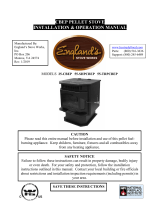
FLOOR AND WALL PROTECTION
Floor Protection
If your floor is constructed of a non-combustible material such as brick or concrete, there is no
need for floor protection. If the floor is constructed of a combustible material such as hardwood,
linoleum, or carpet, then you will be required to use floor protection between the unit and the
combustible. The protection should be U.L. approved or equivalent (ULC if Canada) and must be
large enough to provide a minimum of one inch (1.0”) behind, four inches (4.0”) on both sides of the
stove and at least six inches (6.0”) in the front of the unit. This floor protection is intended as spark
and ember protection only, therefore it need only be non-combustible (there is no required R value).
Wall Protection
From the rear and the sides of this stove only six inches (6”) of clearance is required to paneling, wallpaper
or drywall. The pellet vent pipe usually requires the standard three inches (3”) of clearance, or as recommended
by the manufacturer. Normally additional wall protection is not required with this type unit.
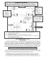
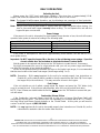
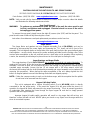
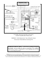
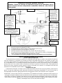
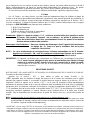
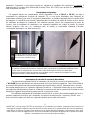
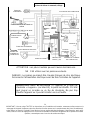
1. If 3” flue pipe exceeds 15’ in length, increase to 4” flue pipe for remaining flue connections.
2. Total flue length should not exceed 35’.
3. Horizontal run not to exceed 4’.
4. Floor protector must extend 6” from front of unit, 4” from sides and 1” from rear.
5. If the total run of outside air connection exceeds 6’, if more than 2 elbows are used, or if a basement install,
use 3” metal pipe (and coupler) instead.
6. Outside Air is mandatory for proper safe operation.
Masonr
y
Connection
Our Part AC-3000 is
acceptable for
through-the-wall
installation.
AC-3100 for 4000+
ft. installations.
(AC-33000 or AC-
33100 if Canada)
Must have minimum
3” adapter before tee
for longer run.
For shorter run (such
as Masonry
Connection below),
tee alone is acceptable.
Basement Installation should be
performed by professional
installer. Use 3” metal pipe and
coupler for Outside Combustion
Air. Minimum 3 feet (3’)
clearance from ground to the
Pellet Vent Exhaust Pipe.
Illustration 1
Freestanding Pellet Installation
Caution: Follow the pipe manufacturer’s installation instructions and directions for
passin
g
throu
g
h combustible walls and ceilin
g
s. Check local codes in
y
our area.
INSTALL VENT AT CLEARANCES SPECIFIED BY THE VENT MANUFACTURE
R

IMPORTANT! READ AND FOLLOW ALL INSTALLATION AND MAINTENANCE INSTRUCTIONS, INCLUDING
CLEANING THE UNIT AS SPECIFIED, AND REPLACING GASKETS ANNUALLY, AND PARTS AS NEEDED.
ENGLAND’S STOVE WORKS IS NOT RESPONSIBLE FOR ANY DAMAGE OR INJURY INCURRED DUE TO NEGLECT, OR
DUE TO UNSAFE INSTALLATION OR USAGE OF THIS PRODUCT. CALL TECHNICAL SUPPORT WITH QUESTIONS.
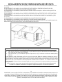
12
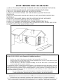
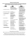
VENT TERMINATION CLEARANCES
A) MIN. 4-FT CLEARANCE BELOW OR BESIDE ANY DOOR OR WINDOW THAT OPENS.
B) MIN. 1-FT CLEARANCE ABOVE ANY DOOR OR WINDOW THAT OPENS.
C) MIN. 2-FT CLEARANCE FROM ANY ADJACENT BUILDING.
D) MIN. 7-FT CLEARANCE FROM ANY GRADE WHEN ADJACENT TO PUBLIC
WALKWAYS.
E) MIN. 2-FT CLEARANCE ABOVE ANY GRASS, PLANTS, OR OTHER COMBUSTIBLE
MATERIALS.
F) MIN. 3-FT CLEARANCE FROM A FORCED AIR INTAKE OF ANY APPLIANCE.
G) MIN. 2-FT CLEARANCE BELOW EAVES OR OVERHANG.
H) MIN. 1-FT CLEARANCE HORIZONTALLY FROM COMBUSTIBLE WALL.
I) MUST BE A MINIMUM OF 36-INCHES ABOVE THE ROOF AND 24-INCHES ABOVE THE
HIGHEST POINT OF THE ROOF WITHIN 10-FEET.
Notes on termination of Pellet Vent Pipe from NFPA211(2006ed.)Section10.4Termination:10.4.5
(See also “FLUE SYSTEM” section of manual AND additional notes above):
- Not less than three (3) feet above any forced air inlet located within ten (10) feet.
- Not less than four (4) feet below, four (4) feet horizontally from, or one (1) foot above any door,
window or gravity air inlet into any building.
- Not less than two (2) feet from an adjacent building, and not less than seven (7) feet above grade
where located adjacent to public walkways.
The exhaust exit shall be arranged so that the flue gases are not directed so that it will affect people, overheat
combustible structures, or enter buildings. Forced draft systems and all parts of induced draft systems under
positive pressure during operation shall be installed gastight or to prevent leakage of combustion products into
a building. Through-the-wall vents shall not terminate over public walkways, or where condensate or vapor
could create hazards or a nuisance.
Be sure to follow local codes and all manufacturer’s instructions (including exhaust pipe).
Consult a professional installer and/or call Technical Support if you have any questions.

IMPORTANT! READ AND FOLLOW ALL INSTALLATION AND MAINTENANCE INSTRUCTIONS, INCLUDING
CLEANING THE UNIT AS SPECIFIED, AND REPLACING GASKETS ANNUALLY, AND PARTS AS NEEDED.
ENGLAND’S STOVE WORKS IS NOT RESPONSIBLE FOR ANY DAMAGE OR INJURY INCURRED DUE TO NEGLECT, OR
DUE TO UNSAFE INSTALLATION OR USAGE OF THIS PRODUCT. CALL TECHNICAL SUPPORT WITH QUESTIONS.
13
OPERATING INSTRUCTIONS
CAUTION: DO NOT OPERATE WITH THE DOOR OPEN.
If door is left open (approximately) two minutes, unit will stop feeding and fire will go out.
Do not burn trash (paper bags, etc.) in this unit.
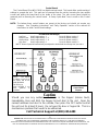
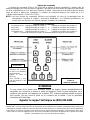
This stove has an induced draft system and is designed to operate continuously, as frequent
shutdown is not required. The digital control board operates the unit with a time delay-relay system;
this system controls the top auger feed rate by operating for a predetermined number of seconds
while the bottom auger runs constantly. The setting of the “Heat Range” touch pad will control the
heat output and the amount of pellets the unit will burn (see “Control Board” section and
Illustration 2). Note: This stove is using solid fuel and will not restart automatically.
* NOTE: Blower Speed will automatically be adjusted to the desired Heat Range that you select.
Horizontal Feed System
This unit has a top and a bottom auger that are separated by four inches (4”); a 1-RPM motor
drives each auger. The top auger intermittently drops pellets to the bottom auger tube, and the bottom
auger pushes the pellets forward to the burn pot. This helps prevent build-up of fuel in the bottom
auger tube. As pellets enter the burn pot the combustion air is drawn across the fuel.
START- UP PROCEDURE
Caution - Never use gasoline, lantern fuel, charcoal lighter fluid, diesel fuel, or any other
flammable liquid to start the fire.
1. Be sure the hopper is clean and free from foreign materials. Be sure there is current at your
outlet (we do recommend a surge protector with our unit).
2. Before your first fire dry run your unit (with no pellets in the hopper) for 20 minutes.
Press the “ON” button to begin the dry run. After the 20 minute dry run, the control board will
return to “OFF.” An error code will appear in the Heat Range and the Blower Speed windows
as “E-2,” which means the unit failed to start normally. After this code is received and you are
sure the unit is working properly, fill the hopper with wood pellets. Do not allow any part of the
bag or any foreign material in the hopper, as this may jam the augers. Ensure that all pellet
matter is cleared from the hopper lid gasket, make sure the hopper lid latches and the door of
the unit are securely closed and press the “ON” button; this will clear the error code and restart
your unit.
Automatic Start-Up
When the “ON” button is pressed from a cold start, the unit is in “Start-Up” (after 3 seconds, there
will be an “S U” in the Heat Range and Blower Speed windows to verify this). While in this mode,
the unit has a preset heat range and will remain in this mode for 20 minutes to prevent the unit
from over-firing. During this start-up period you can set the Control Board at the setting you desire;
after the start-up is complete, the unit will operate at the user setting.
Manually Starting Your Unit
In the event the Auto-Start does not initiate, you may manually start your unit. To manually start
your unit, first clean any pellets out of the burn pot (to prevent over-feeding). Place a handful of
new pellets in the burn pot, then spread a small amount of pellet fire starter over the pellets and
ignite them. After the pellets ignite, close the door to your unit and press the “ON” button (if the
door is closed before the pellets fully ignite, the Exhaust Blower could put out the fire).
Recommended fire starter materials: Wax-impregnated wood chips, cardboard cubes or
firestarter chips designed for pellet stoves. Follow any manufacturer’s directions for these
products, and NEVER place any firestarter on any hot surface or hot coals. Never use gasoline,

IMPORTANT! READ AND FOLLOW ALL INSTALLATION AND MAINTENANCE INSTRUCTIONS, INCLUDING
CLEANING THE UNIT AS SPECIFIED, AND REPLACING GASKETS ANNUALLY, AND PARTS AS NEEDED.
ENGLAND’S STOVE WORKS IS NOT RESPONSIBLE FOR ANY DAMAGE OR INJURY INCURRED DUE TO NEGLECT, OR
DUE TO UNSAFE INSTALLATION OR USAGE OF THIS PRODUCT. CALL TECHNICAL SUPPORT WITH QUESTIONS.
14
lantern fuel, kerosene, charcoal lighter fluid, diesel fuel or any other flammable liquid to start the
fire. Do not use the manual startup method if the igniter is working. NEVER place firestarter near
the igniter. If you have continued problems with the Auto-Start Igniter, call Technical Support.
E-Codes
“E-Codes,” or Error Codes, are codes that will appear in the Heat Range and Blower Speed
windows of the Control Board if your unit experiences problems. If you receive any of these codes,
first attempt to reset your unit by pressing the “ON” button (only once). If the unit continues to display
any E-Code(s), please contact Technical Support at (800) 245-6489 before further attempting to
restart your unit.
1. E-1 = Vacuum Loss
2. E-2 = Fail to Start
3. E-3 = Over Temperature Limit
NOTE: “E-0” indicates “No Error”
First Fire: Adjust the “Heat Range” to a “5” setting and allow the stove to burn in this manner
for at least three (3) hours. This will allow the unit to “cure out” as the paint and the
oils from the manufacturing process burn off. We recommend you open doors and
windows in your dwelling during this process.
Subsequent Cold Starts: In a cold start situation, the unit should be operated at a “5” setting
until the room air blower begins to operate.
NOTE: The start-up cycle for this unit with the Auto-Start Igniter is 13 minutes. Press the
“ON” button only once on start-up. Pressing the “ON” button a second time during
the start-up cycle will cause the start-up cycle to begin again.
IMPORTANT: If the unit fails to start properly, or does not properly complete the Shut-Down
procedure, open the closest outside door and a window to eliminate the home’s
natural draft BEFORE opening the stove’s door or hopper lid. This will allow any
smoke to exit through the external air hook-up instead of spilling into the home.
SHUT-DOWN PROCEDURE
WARNING: NEVER SHUT DOWN THIS UNIT BY UNPLUGGING IT FROM THE POWER SOURCE.
Refer to the following instructions:
Press the “OFF” touch pad to put the stove in the “Shut-Down” mode. There will be an
“S D” in the Heat Range and Blower Speed windows while the unit is shutting down to verify this. At
this time the red light above the “OFF” pad will illuminate. When the “OFF” pad is touched the top
auger will instantly stop feeding pellets to the bottom auger tube, but the room air blower, exhaust
blower and bottom auger will continue to operate. When the internal temperature drops to 95 degrees
the room air blower will cease to operate, and when the internal temperature drops to 90 degrees the
bottom auger and exhaust blower will stop. The red light will then shut off and the entire stove will be
shut down. The hotter the unit is operating, the longer it will take for the stove to complete the Shut-
Down cycle.
Note: The unit will exit the Shut-Down cycle if you press any buttons during Shut-Down.
Note: If the room temperature stays above 70 degrees the stove will remain in the Shut Down mode
for 60 minutes, regardless of the temperature reading at the heat sensor. If the stove stays on
longer than 60 minutes the unit will automatically turn off.

IMPORTANT! READ AND FOLLOW ALL INSTALLATION AND MAINTENANCE INSTRUCTIONS, INCLUDING
CLEANING THE UNIT AS SPECIFIED, AND REPLACING GASKETS ANNUALLY, AND PARTS AS NEEDED.
ENGLAND’S STOVE WORKS IS NOT RESPONSIBLE FOR ANY DAMAGE OR INJURY INCURRED DUE TO NEGLECT, OR
DUE TO UNSAFE INSTALLATION OR USAGE OF THIS PRODUCT. CALL TECHNICAL SUPPORT WITH QUESTIONS.
15
DAILY OPERATION
Refueling the Unit
Always press the “OFF” touch pad before refueling. This stove has a (approximately) 60-lb.
hopper, and should be refilled when the hopper level drops to three or four inches.
Note: The hopper lid will be warm; therefore, you should always use some type of hand protection.
NEVER place your hand near the auger while the stove is operating.
Note: Always ensure that all pellet matter is cleared from the hopper lid gasket before closing. Be
sure to close and latch hopper securely before re-firing. Do not operate this unit with the
hopper lid open or unsecured.
Power Outage
If the power to the unit is interrupted for approximately three minutes or less, the unit will resume
operation when power is restored according to the following table:
Unit’s State Before Power Loss State When Power Returns
ON Start-Up
Start-Up Start-Up
Shut-Down Shut-Down
OFF OFF
If the power is interrupted for more than (approximately) three minutes, the unit will be “OFF”
when power returns.
Important: Do NOT open the hopper lid or the door to the unit during power outage. Open the
closest outside door and a window to eliminate the home’s natural draft.
Wait for power to be restored and then press the “ON” button to re-start the unit, if necessary.
We highly recommend the use of a surge protector with your unit, as power surges and failures
can affect the operation of any electrical appliance.
We do not recommend leaving home with the stove on the higher heat ranges; it is recommended
that the stove be left on the lower heat ranges (Heat Range setting 1 or 2).
NOTE: Remember: 1) It is very important for the unit to be vented properly (see instructions on
Outside Air), as the natural draft is needed to clear the smoke from the stove. 2) Do not open
the hopper lid (or the unit’s door). This may cause fire to burn in the hopper.
Fuel Outage
If the unit should run out of pellets, simply reload the hopper and press the “ON” button (only
once) to re-start the unit. If the unit runs without pellets, after one hour the unit will shut down.
NOTE: Even if flames are visible inside the fire box always
press the “ON” button to ensure that your
unit will restart.
Combustion Blower Failure
If the Combustion (exhaust) Blower should fail on this unit, a Vacuum Shut-Down Switch will
automatically stop the stove. This will shut your unit completely off, and there will be an “E-1” code in
the Heat Range and Blower Speed windows on the Control Board. At this point you will need to
contact Technical Support at (800) 245-6489.
NOTE: It is very important for the unit to be vented properly (see instructions on Outside Air), as the
natural draft is needed to clear the smoke from the stove.

IMPORTANT! READ AND FOLLOW ALL INSTALLATION AND MAINTENANCE INSTRUCTIONS, INCLUDING
CLEANING THE UNIT AS SPECIFIED, AND REPLACING GASKETS ANNUALLY, AND PARTS AS NEEDED.
ENGLAND’S STOVE WORKS IS NOT RESPONSIBLE FOR ANY DAMAGE OR INJURY INCURRED DUE TO NEGLECT, OR
DUE TO UNSAFE INSTALLATION OR USAGE OF THIS PRODUCT. CALL TECHNICAL SUPPORT WITH QUESTIONS.
16
ASH REMOVAL AND DISPOSAL
IMPORTANT: While the amount of ash generated by this unit is not excessive compared to
log-burning woodstoves, keeping the unit clean and free of ash is essential
for
peak performance. Too much ash build-up hampers airflow and reduces the
unit’s efficiency, and can cause smoke-back. Follow these directions at least
as frequently as the schedule below, or more often if needed.
Daily Ash Maintenance
Press the “OFF” touch pad and allow the stove to burn for five (5) minutes prior to opening the
door. A long-handled screwdriver or long-handled putty knife can be used to scrape off any build-up
or crust in the burn pot area. This can then be pushed to the left or right into the ash storage area.
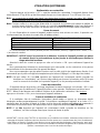
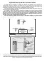
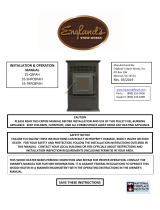
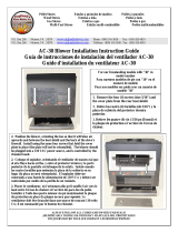
Semi-Weekly Ash Removal
Twice each week: Shut the unit down by
pressing the “OFF” pad and allowing the unit to go
through the complete Shut-Down cycle. Allow the
unit to completely cool down and then remove the
ashes with a scoop. The ashes should be placed in a
non-combustible container with an airtight lid and
should always be placed on a non-combustible
surface or on the ground until completely cooled and
free of hot cinders.
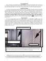
Once the ash is removed, the burn pot should be
given a thorough inspection. Remove and clean the
burn pot wear plate (refer to the exploded diagram in
the rear of this manual – Illustration 6, and the close-
up diagram shown here), and remove any ash build-
up in the area below the wear plate. Also, be sure
there are no ashes or obstructions in the tube under
the wear plate. Check for any build-up in the front of the burn area. Clean out all air holes (if
necessary a 1/8” drill bit can be used) --these air holes should be kept clean, as they supply
combustion air under and around the pellet fuel. The burn pot assembly should also be thoroughly
cleaned, including the feed auger and feed tube. When replacing the wear plate, ensure that it lies
flat in the firebox and no gaps (from ash residue) are under it.
IMPORTANT: Ash build-up under the wear plate can cause the unit to malfunction.
NOTE: The instructions below concerning the cleaning of the burn pot and wear plate area are
especially important to the function of your stove. Failure to follow them regularly can result in
burn-back and can damage your unit and/or void your warranty.
Illustration 2
Bottom Auger Tube
Disposal of Ashes
Ashes should be placed in a metal container with a tight fitting lid. The closed container of ahses should
be placed on a noncombustible floor or on the ground, well away from all combustible materials, pending
final disposal. If the ashes are disposed of by burial in soil or otherwise locally dispersed, they should be
retained in the closed container until all cinders have been thoroughly cooled.
As with any maintenance concerning this unit, be sure the unit is “OFF” and has completed the Shut-
Down cycle BEFORE beginning. Be aware that metal parts in the firebox can remain HOT long after
the fire has gone out and EVEN after the Shut-Down cycle is complete. Always use extreme caution
when handlin
g
potentiall
y
hot stove parts, even if
y
ou think the
y
should be cold.

IMPORTANT! READ AND FOLLOW ALL INSTALLATION AND MAINTENANCE INSTRUCTIONS, INCLUDING
CLEANING THE UNIT AS SPECIFIED, AND REPLACING GASKETS ANNUALLY, AND PARTS AS NEEDED.
ENGLAND’S STOVE WORKS IS NOT RESPONSIBLE FOR ANY DAMAGE OR INJURY INCURRED DUE TO NEGLECT, OR
DUE TO UNSAFE INSTALLATION OR USAGE OF THIS PRODUCT. CALL TECHNICAL SUPPORT WITH QUESTIONS.
17
Monthly Ash Removal
The large baffle plate (12-5/8” x 9-3/8”) that rests above and behind the burn pot (refer to the
section on “Proper Impingement Plate Placement” and the exploded diagram in the rear of this
manual – Illustration 6) should be removed monthly. This can be done by lifting up the plate and
pulling it out. The area behind the plate should then be cleaned thoroughly, and the plate placed back
in the original position.
Use a screwdriver or chisel and break any creosote build-up in the front of the unit, where the
pellets are fed into the burn pot from the Bottom Auger Tube (see Illustration 2). Moisture in the
pellets and resulting build-up in this area can cause the bottom auger to “squeal” or squeak.
Also inspect your flue pipes, and remove ash buildup from the clean-out tee.
Carbon Removal: During normal operation carbon from the combustion of pellet fuel will tend to
build up on the tip of the auger, on the wear plate and sides of the fire pot, and in the mouth of the
feed tube. It is essential that this residue be removed to ensure trouble free operation of the unit. The
frequency with which this carbon must be removed varies with brands of pellets, depending on
moisture content, wood type, foreign material (dirt, etc.) in pellets, and other factors.
To remove this carbon, simply scrape it off using the blade of a flat tipped screwdriver or similar
instrument; also, to remove it from the feed tube, scrape as much as can be easily reached, then
insert an emery board (i.e. fingernail file made from a popsicle stick and sandpaper) between the feed
auger and the feed tube and sand out any residue not removed from scraping alone. Clearing this
carbon residue from the feed tube is essential for proper operation of the feed auger, which is
designed to float freely in the feed tube allowing smooth fuel flow, a lesser possibility of a jam, and a
quieter unit.
Annual Cleaning
The stove and the flue system should be given a complete cleaning at the end of the heating
season. Remove the burn pot assembly, clean it thoroughly, and re-install it (refer to
Illustration 6); this will require new gasket for the burn pot. Be sure to tighten the set screws when
you replace them, but do not over-tighten. In addition to the cleaning mentioned for semi-weekly and
monthly, the Combustion (exhaust) Blower should be removed annually and the blower tube
vacuumed of any ash build-up. Note: There is a Combustion Motor Gasket (Part PU-CMG), which
allows you to remove the motor from the Combustion Blower housing, clean your stove, and replace
the motor and gasket without having to remove the entire Combustion Blower. However, if you must
remove or replace the entire Combustion Blower, a new blower flange gasket (Part # PU-CBG) should
be added between the blower flange and the steel exhaust tube.
Soot and Fly Ash: Formation and Need for Removal
The products of combustion will contain small particles of fly ash. The fly ash will collect in the
exhaust venting system and restrict the flow of the flue gases. Incomplete combustion, such as
that which occurs during startup, shutdown or incorrect operation of the room heater will lead to
some soot formation which will collect in the exhaust venting system. The exhaust venting
system should be inspected at least once every year to determine if cleaning is necessary.

IMPORTANT! READ AND FOLLOW ALL INSTALLATION AND MAINTENANCE INSTRUCTIONS, INCLUDING
CLEANING THE UNIT AS SPECIFIED, AND REPLACING GASKETS ANNUALLY, AND PARTS AS NEEDED.
ENGLAND’S STOVE WORKS IS NOT RESPONSIBLE FOR ANY DAMAGE OR INJURY INCURRED DUE TO NEGLECT, OR
DUE TO UNSAFE INSTALLATION OR USAGE OF THIS PRODUCT. CALL TECHNICAL SUPPORT WITH QUESTIONS.
18
MAINTENANCE
CAUTION: UNPLUG THE UNIT PRIOR TO ANY SERVICE WORK!
SEE EXPLODED DIAGRAM (ILLUSTRATION 6) FOR PARTS REFERENCE
Parts Orders: (800) 516-3636 www.englanderstoves.com Questions: (800) 245-6489
NOTE: Visit our web site for downloadable maintenance sheets and/or a service video that details
and illustrates the following maintenance tasks.
Rear Panel Removal
WARNING: To perform any maintenance inside the rear of the unit, the stove must be out
(no fire), cooled down and unplugged. Electrical shock can occur if the unit is
not unplugged from power.
To remove the rear panel, simply loosen the eight (8) screws (size 5/16”) and flex the panel. The
panel should come off without fully removing the screws.
Instructions for maintenance and part replacement procedures can be found on:
www.englanderstoves.com
Auger Motors
The Auger Motor and gearbox are one complete assembly (Part # PU-047040), and can be
removed by disconnecting the power leads and loosening the (
5
/
16
” head) set bolt in front of the
assembly. This bolt tightens down on the flat side of the gear shaft and locks the gear shaft and auger
shaft together – once the bolt is loosened, the entire assembly will slide from the locking collar. There
are two motor assemblies on the unit, and both rest on a shelf when not in operation. When replacing
a motor, the assembly should always be placed to rest on this shelf prior to starting the unit.
Auger Bearings and Auger Shafts
The auger bearings (Part # PU-UCF204-12) are a sealed unit and do not require lubrication
. To
replace the Top Auger, all the fuel must be removed from the hopper as well as from the Top Auger
assembly. Once this is done, the four bolts that hold in the bearing can be removed, followed by the
complete auger assembly. Loosen the two (2) set screws with a 1/8” allen wrench, which will
disconnect the bearing from the shaft (the bearing assembly and auger assembly can be replaced by
reversing this procedure). When placing the auger assemblies in the unit, always tighten the four
bolts in a diagonal pattern to ensure the bearings and shafts are aligned properly.
NOTE: Follow the same procedure to work on the bottom auger, with the exception that the pellets
do not have to be removed from the hopper.
Hopper Lid Safety Switch
This unit is equipped with a hopper lid safety switch (Part # AC-HLSB) which is directly
connected to the top auger motor. In the event the hopper lid is left open while the stove is in
operation, the hopper lid switch will prevent the top auger from turning. This is to prevent byproducts
of combustion from entering the home through the open hopper lid and also to simply prevent
operation with the hopper lid open.
Improper hopper lid safety switch operation will result in a top auger that will not turn and
therefore a stove that will not burn. NEVER place your hand or any object near the auger while the
stove is connected to power.

IMPORTANT! READ AND FOLLOW ALL INSTALLATION AND MAINTENANCE INSTRUCTIONS, INCLUDING
CLEANING THE UNIT AS SPECIFIED, AND REPLACING GASKETS ANNUALLY, AND PARTS AS NEEDED.
ENGLAND’S STOVE WORKS IS NOT RESPONSIBLE FOR ANY DAMAGE OR INJURY INCURRED DUE TO NEGLECT, OR
DUE TO UNSAFE INSTALLATION OR USAGE OF THIS PRODUCT. CALL TECHNICAL SUPPORT WITH QUESTIONS.
19
Convection Blower
The Convection (room air) Blower (Part # PU-4C447) is located on the left side of the unit and can
be removed by disconnecting the power leads and removing the four mounting screws. Once this is
done, the blower will slide out of the stove. This procedure can be reversed to install a new blower.
Combustion Blower
To replace the Combustion (exhaust) Blower (Part #PU-076002B), the power leads and the pellet
vent pipe must be disconnected. Next, remove the screws that hold the blower to the steel exhaust
tube and slide the blower from the stove. Note: There is a Combustion Motor Gasket (Part PU-
CMG), which allows you to remove the motor from the Combustion Blower housing, clean your stove,
and replace the motor and gasket without having to remove the entire Combustion Blower. If cleaning
your blower, the blower impeller, blower tube and steel blower exhaust tube on the unit should be
brushed and vacuumed. However, if you must remove or replace the entire
Combustion Blower, a
new blower flange gasket (Part # PU-CBG) should be added between the blower flange and the steel
exhaust tube.
Vacuum Switch
This unit is equipped with Vacuum Shut Down Switches (Part # PU-VS and CU-VS), which help
control various functions of the unit. If an operational error occurs in the unit, a switch will either stop
the top (feed) auger or shut the unit off; if the unit turns off an E-1 Code (error code) will appear in the
Heat Range and Blower Speed windows of the Control Board. Situations which could cause this
include power failure, Combustion Blower failure, improper flue installation, a blocked flue (from
rodents, nests, etc.), or “dirty burning” from burning improper fuel (see “Important Information” at the
beginning of the manual).
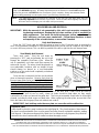
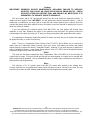
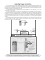
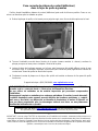
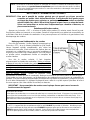
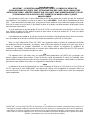
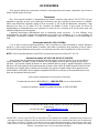
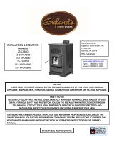
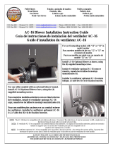
“Door Ajar” Vacuum Switch Port
If necessary, remove right side louver
to determine where vacuum port enters
firebox
Inside right wall of firebox
NOTE: The "door ajar" vacuum switch port must be kept clean, or the top auger will cease to function.
Locate the port hole on the right wall of the burn chamber (you may remove the right louver to follow the
vacuum tube to locate the hole) and, with the stove unplugged and cooled down, use a brush or pipe
cleaner (not a vacuum) to keep this port clear of ash or other debris (see picture).

IMPORTANT! READ AND FOLLOW ALL INSTALLATION AND MAINTENANCE INSTRUCTIONS, INCLUDING
CLEANING THE UNIT AS SPECIFIED, AND REPLACING GASKETS ANNUALLY, AND PARTS AS NEEDED.
ENGLAND’S STOVE WORKS IS NOT RESPONSIBLE FOR ANY DAMAGE OR INJURY INCURRED DUE TO NEGLECT, OR
DUE TO UNSAFE INSTALLATION OR USAGE OF THIS PRODUCT. CALL TECHNICAL SUPPORT WITH QUESTIONS.
20
Gaskets
IMPORTANT: IMPROPER GASKET MAINTENANCE, INCLUDING FAILURE TO REPLACE
GASKETS, CAN CAUSE AIR LEAKS RESULTING IN SMOKE-BACKS. CHECK
GASKETS OFTEN FOR AIRTIGHT SEAL AND REPLACE AS NECESSARY. IT IS
MANDATORY TO REPLACE GASKETS ANNUALLY.
This unit comes with a 3/4” rope gasket around the door that should be replaced annually. To
replace the door gasket (Part # AC-DGKC), the old gasket must first be removed entirely — prior to
adding the new adhesive, you may have to scrape the old cement from the door channel. Once the
cement and gasket have been added, the door should be closed and latched for twenty-four hours to
allow the cement to harden.
If you are replacing the window gasket (Part #AC-GGK), the new gasket will already have
adhesive on one side. Remove the paper on the adhesive side and place the gasket around the
outside edge of the glass by forming a “U” with your fingers and placing the gasket around the glass.
It is important to change the hopper lid gasket if it shows any wear. Be sure to replace the hopper
lid gasket annually, or sooner if necessary.
Note: There is a Combustion Motor Gasket (Part PU-CMG), which allows you to remove the
motor from the Combustion Blower housing, clean your stove, and replace the motor and gasket
without having to remove the entire Combustion Blower. However, if you must remove or replace the
entire Combustion Blower, a new blower flange gasket (Part # PU-CBG) should be added between
the blower flange and the steel exhaust tube.
Finish
This new unit has been painted with High-Temperature Paint (AC-MBSP) that should retain its
original look for years. If the unit should get wet and rust spots appear, the spots can be sanded with
plain steel wool and repainted. We recommend this paint, as others may not adhere to the surface or
withstand the high temperatures.
Glass
This unit has a 9” x 9” ceramic glass (Part #AC-G9, comes with gasket) in the viewing door.
Surface scratches are acceptable and normal, but if this glass becomes cracked in any area, the unit
should be shut down and the window replaced with this high-temperature ceramic glass.
La page est en cours de chargement...
La page est en cours de chargement...
La page est en cours de chargement...
La page est en cours de chargement...
La page est en cours de chargement...
La page est en cours de chargement...
La page est en cours de chargement...
La page est en cours de chargement...
La page est en cours de chargement...
La page est en cours de chargement...
La page est en cours de chargement...
La page est en cours de chargement...
La page est en cours de chargement...
La page est en cours de chargement...
La page est en cours de chargement...
La page est en cours de chargement...
La page est en cours de chargement...
La page est en cours de chargement...
La page est en cours de chargement...
La page est en cours de chargement...
La page est en cours de chargement...
La page est en cours de chargement...
La page est en cours de chargement...
La page est en cours de chargement...
La page est en cours de chargement...
La page est en cours de chargement...
La page est en cours de chargement...
La page est en cours de chargement...
La page est en cours de chargement...
La page est en cours de chargement...
La page est en cours de chargement...
La page est en cours de chargement...
La page est en cours de chargement...
La page est en cours de chargement...
La page est en cours de chargement...
La page est en cours de chargement...
La page est en cours de chargement...
La page est en cours de chargement...
La page est en cours de chargement...
La page est en cours de chargement...
La page est en cours de chargement...
-
 1
1
-
 2
2
-
 3
3
-
 4
4
-
 5
5
-
 6
6
-
 7
7
-
 8
8
-
 9
9
-
 10
10
-
 11
11
-
 12
12
-
 13
13
-
 14
14
-
 15
15
-
 16
16
-
 17
17
-
 18
18
-
 19
19
-
 20
20
-
 21
21
-
 22
22
-
 23
23
-
 24
24
-
 25
25
-
 26
26
-
 27
27
-
 28
28
-
 29
29
-
 30
30
-
 31
31
-
 32
32
-
 33
33
-
 34
34
-
 35
35
-
 36
36
-
 37
37
-
 38
38
-
 39
39
-
 40
40
-
 41
41
-
 42
42
-
 43
43
-
 44
44
-
 45
45
-
 46
46
-
 47
47
-
 48
48
-
 49
49
-
 50
50
-
 51
51
-
 52
52
-
 53
53
-
 54
54
-
 55
55
-
 56
56
-
 57
57
-
 58
58
-
 59
59
-
 60
60
-
 61
61


England's Stove Works 55-TRP22 Installation & Operation Manual
- Catégorie
- Cheminées
- Taper
- Installation & Operation Manual
- Ce manuel convient également à
dans d''autres langues
- English: England's Stove Works 55-TRP22
Documents connexes

Autres documents
-
 Englander 25-IPS Manuel utilisateur
-
 Summers Heat 55-SHP10L Manuel utilisateur
-
 Englander 25-PDVCH Manuel utilisateur
-
 Englander 10-CPM Guide d'installation
-
 Englander 25-EPI Manuel utilisateur
-
 Summers Heat 55-SHPCBEP Manuel utilisateur
-
 Englander 25-CBPAH Manuel utilisateur
-
 Summers Heat 55-SHPCAB80S Mode d'emploi
-
 Englander AC-30 Guide d'installation
-
 Englander AC-16 Guide d'installation


