Bunn JDF-2S Guide d'installation
- Catégorie
- Cafetières
- Taper
- Guide d'installation
Ce manuel convient également à

1
44744.7003 B 01/19 © 2018 Bunn-O-Matic Corporation
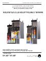
INSTALLATION & OPERATING GUIDE
Bunn-O-Matic Corporation of Canada
280 Industrial Parkway South, Aurora Ontario L4G 3T9
Phone (905) 841-2866 | Fax (905) 841-2775
www.bunn.com
JDF-2S, JDF-4S
Silver Series
®
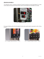
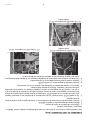
JDF-2S & JDF-4S PH or PC with Non LIT or LIT Graphic Door
JDF-2S & JDF-4S PH or PC with LIT Segment Door

392, AutoPOD, AXIOM, BrewLOGIC, BrewMETER, Brew Better Not Bitter, BrewWISE, BrewWIZARD, BUNN Espress, BUNN
Family Gourmet, BUNN Gourmet, BUNN Pour-O-Matic, BUNN, BUNN with the stylized red line, BUNNlink, Bunn-OMatic,
Bunn-O-Matic, BUNNserve, BUNNSERVE with the stylized wrench design, Cool Froth, DBC, Dr. Brew stylized Dr. design,
Dual, Easy Pour, EasyClear, EasyGard, FlavorGard, Gourmet Ice, Gourmet Juice, High Intensity, iMIX, Infusion Series, In-
tellisteam, My Café, Phase Brew, PowerLogic, Quality Beverage Equipment Worldwide, Respect Earth, Respect Earth with
the stylized leaf and coffee cherry design, Safety-Fresh, savemycoffee.com, Scale-Pro, Silver Series, Single, Smart Funnel,
Smart Hopper, SmartWAVE, Soft Heat, SplashGard, The Mark of Quality in Beverage Equipment Worldwide, ThermoFresh,
Titan, trifecta, Velocity Brew, A Partner You Can Count On, Air Brew, Air Infusion, Beverage Bar Creator, Beverage Profit
Calculator, Brew better, not bitter., BUNNSource, Coffee At Its Best, Cyclonic Heating System, Daypart, Digital Brewer
Control, Nothing Brews Like a BUNN, Pouring Profits, Signature Series, Tea At Its Best, The Horizontal Red Line, Ultra are
either trademarks or registered trademarks of Bunn-O-Matic Corporation.
BUNN-O-MATIC COMMERCIAL PRODUCT WARRANTY
Bunn-O-Matic Corporation of Canada (“Bunn”) warrants equipment manufactured by it as follows:
1) Airpots, thermal carafes, decanters, GPR servers, iced tea/coffee dispensers, MCP/MCA pod brewers
thermal servers and Thermofresh servers (mechanical and digital) - 1 year parts and 1 year labour.
2) All other equipment - 2 years parts and 1 year labour plus added warranties as specified below:
a) Electronic circuit and/or control boards - parts and labour for 3 years.
b) Compressors on refrigeration equipment - 5 years parts and 1 year labour.
c) Grinding burrs on coffee grinding equipment to grind coffee to meet original factory screen sieve
analysis - parts and labour for 4 years or 40,000 pounds of coffee, whichever comes first.
These warranty periods run from the date of installation. Bunn warrants that the equipment manufactured
by it will be commercially free of defects in material and workmanship existing at the time of manufacture and
appearing within the applicable warranty period. This warranty does not apply to any equipment, component
or part that was not manufactured by Bunn or that, in Bunn’s judgement, has been affected by misuse, neglect,
alteration, improper installation or operation, improper maintenance or repair, non periodic cleaning and descaling,
equipment failures related to poor water quality, damage or casualty. In addition, the warranty does not apply to
replacement of items subject to normal use including but not limited to user replaceable parts such as seals and
gaskets. This warranty is conditioned on the Buyer 1) giving Bunn prompt notice of any claim to be made under
this warranty by telephone at (905) 841-2866 or by writing to 280 Industrial Parkway South, Aurora, Ontario, L4G
3T9. 2) if requested by Bunn, shipping the defective equipment prepaid to an authorized Bunn service location;
and 3) receiving prior authorization from Bunn that the defective equipment is under warranty.
THE FOREGOING WARRANTY IS EXCLUSIVE AND IS IN LIEU OF ANY OTHER WARRANTY, CONDITION,
WRITTEN OR ORAL, EXPRESS OR IMPLIED, INCLUDING, BUT NOT LIMITED TO, ANY IMPLIED WARRANTY
OF EITHER MERCHANTABILITY, MERCHANTABLE QUALITY OR FITNESS FOR A PARTICULAR PURPOSE.The
agents, dealers or employees of Bunn are not authorized to make modifications to this warranty or to make
additional warranties that are binding on Bunn. Accordingly, statements by such individuals, whether oral or
written, do not constitute warranties and should not be relied upon.
If Bunn determines in its sole discretion that the defective equipment is covered by warranty, Bunn, at its
exclusive option while the equipment is under warranty, shall either 1) provide at no charge replacement parts
and/or labour (during the applicable parts and labour warranty periods specified above) to repair the defective
components, provided that this repair is done by a Bunn Authorized Service Representative; or 2) shall replace
the equipment or refund the purchase price for the equipment.
THE BUYER’S REMEDY AGAINST BUNN FOR THE BREACH OF ANY OBLIGATION ARISING OUT OF THE
SALE OF THIS EQUIPMENT, WHETHER DERIVED FROM WARRANTY OR OTHERWISE, SHALL BE LIMITED, AT
BUNN’S SOLE OPTION AS SPECIFIED HEREIN, TO REPAIR, REPLACEMENT OR REFUND.
In no event shall Bunn be liable for any other damage or loss, including, but not limited to, lost profits, lost
sales, loss of use of equipment, claims of Buyer’s customers, cost of capital, cost of down time, cost of substitute
equipment, facilities or services, or any other special, incidental, consequential or punitive damages.
RETURN POLICY
CONTACT PLANT FOR RETURN MATERIAL AUTHORIZATION. ALL RETURNS MUST
BE AUTHORIZED BY BUNN-O-MATIC AND ARE SUBJECT TO A RETURN CHARGE.
2
8/12

3
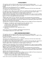
USER NOTICES
Carefully read and follow all notices on the equipment and in this manual. They were written for your protec-
tion. All notices are to be kept in good condition. Replace any unreadable or damaged labels.
CONTENTS
Warranty ........................................................................................................................ 2
User Notices .................................................................................................................. 3
Initial Set-Up & Electrical Requirements ........................................................................ 4
CE Requirements ........................................................................................................... 4
Initial Fill ........................................................................................................................ 5
Plumbing Requirements ................................................................................................ 5
Door Cover Installation .................................................................................................. 6
Plumbing Hookup .......................................................................................................... 7
Operating Controls ......................................................................................................... 9
Dispenser Use .............................................................................................................. 11
Portion Control Option ................................................................................................. 11
Cleaning ....................................................................................................................... 13
Adjustments & Optional Settings ................................................................................. 15
Loading ........................................................................................................................ 16
Priming ........................................................................................................................ 16
Function Lists .............................................................................................................. 19
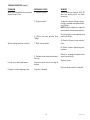
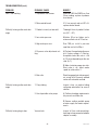
Troubleshooting ........................................................................................................... 21
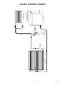
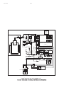
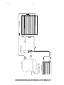
Coolant Diagram .......................................................................................................... 27
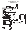
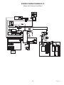
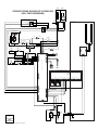
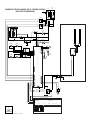
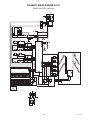
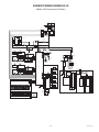
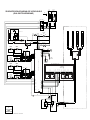
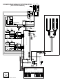
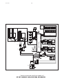
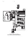
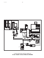
Schematic Wiring Diagram .......................................................................................... 28
Quick Setup Guide ....................................................................................................... 32
44744.2 092517
27442.7000
00986.7000
33461.7012 JDF-2S 220-230V
33461.7014 JDF-4S 220-230V
Moving Parts.
Risk of Electrical Shock.
WARNING
AVERTISSEMENT
Pièces amovibles.
Risk de choc électrique.
Ne pas utiliser l’appareil lorsque
le panneau est enlevé.
Debrancher le cordon
d’alimentation de l’appareil avant
de faire l’entretien.
Do not operate unit with
this panel removed.
Disconnect power
before servicing unit.
WARNING
00986.7000M 10/14 ©1994 Bunn-O-Matic Corporation
Use only on a properly protected
circuit capable of the rated load.
Electrically ground the chassis.
Follow national/local electrical codes.
Do not use near combustibles.
Do not deform plug or cord.
AVERTISSEMENT
FAILURE TO COMPLY RISKS EQUIPMENT
DAMAGE, FIRE OR SHOCK HAZARD.
READ THE ENTIRE OPERATING MANUAL INCLUDING
THE LIMIT OF WARRANTY AND LIABILITY BEFORE
BUYING OR USING THIS PRODUCT.
THIS EQUIPMENT IS ENERGIZED AT ALL TIMES UNLESS
ELECTRICALLY DISCONNECTED.
TOUT MANQUEMENT À SE CONFORMER À CES DIRECTIVES PEUT
ENTRAINER DES DOMMAGES À L'ÉQUIPMENT OU PRODUIRE DES
DANGERS D'INCENDIE OU D'ÉLECTROCUTION.
VEUILLEZ LIRE LE MANUEL DE FONCTIONEMENT
EN ENTIER, Y COMPRIS LES LIMITES DE GARANTIES ET
RESPONSABILITÉS,AVANT D’ACHETER
OU D'UTILISER LE PRÉSENT PRODUIT.
L' ÉQUIPEMENT EST TOUJOURS SOUS TENSION
LORSQU'IL N'EST PAS DÉBRANCHÉ.
N'utilisez que sur un circuit protégé
adapté à la charge nominale.
Toujours mettre le boitier à la masse.
Se conformer aux codes national ou local
délectricité.
Garder les products combustibles á distance.
Ne pas déformer la fiche ou le cordon.
CHARGE
Type R134A, Amount 283 g (10 oz) GWP 1430, CO2 equivalent 0.40t
Design Pressures:
High 335 psi (23 bar) (2.31 MPa)
Low 88 psi (6 bar) (0.61 MPa)
Contains fluorinated greenhouse gases covered
by the Kyoto Protocol. Hermetically sealed system.
Type R134A, capacité 283 g (10 oz) PRG 1430, éq. CO2 0,40 t
Pression nominale:
haute 335 lb/po2 (23 bar) (2,31 MPa)
basse 88 lb/po2 (6 bar) (0,61 MPa)
Ce produit contient des gaz à effet de serre fluorés visés par le protocole de
Kyoto. Système hermétiquement scellé.
CHARGE
Type R134A, Amount 255 g (9 oz) GWP 1430, CO2 equivalent 0.36t
Design Pressures:
High 255 psi (17.6 bar) (1.76 MPa)
Low 36 psi (2.5 bar) (0.25 MPa)
Contains fluorinated greenhouse gases covered
by the Kyoto Protocol. Hermetically sealed system.
Type R134A, capacité 255 g (9 oz) PRG 1430, éq. CO2 0,36 t
Pression nominale:
haute 255 lb/po2 (17,6 bar) (1,76 MPa)
basse 36 lb/po2 (2,5 bar) (0,25 MPa)
Ce produit contient des gaz à effet de serre fluorés visés par le protocole de
Kyoto. Système hermétiquement scellé.
33461.7001 JDF-2S 120V
33461.7000 JDF-4S 120V
CHARGE
Type R134A, Amount 9 oz (255 gm)
Design Pressures: High 255 Low 36
CHARGE
Type R134A, Quantité 9 oz (255 gm)
Pression requise: Haute 255 Basse 36
CHARGE
Type R134A, Amount 10 oz (283 gm)
Design Pressures: High 335 Low 88
CHARGE
Type R134A, Quantité 10 oz (283 gm)
Pression requise: Haute 335 Basse 88
12559.7103
HAZARDOUS VOLTAGE
TENSION DANGEREUSE
DISCONNECT FROM POWER
SOURCE BEFORE REMOVING!
DÉCONNECTER DE LA
SOURCE D'ALIMENTATION
AVANT D’ENLEVER !
WARNING AVERTISSEMENT
00656.7000
Cet équipement doit être installé conformément au code
Canadien de plomberie et aux règlements de santé et de
sécurité qui s’ appliquent. Les modèles destinés à être
installés ailleurs qu’au Canada doivent respecter les codes de
plomberie et d’hygiène de la localité.
This equipment must be installed to comply with Canadian
Plumbing Codes and applicable health and safety regulations.
For models installed outside Canada, comply with the
applicable Plumbing /Sanitation Code.

4
44744.2 031116
CE REQUIREMENTS
• This appliance must be installed in locations where it can be overseen by trained personnel.
• For proper operation, this appliance must be installed where the temperature is between 5°C to 32°C and 50%
humidity.
• Appliance shall not be tilted more than 10° for safe operation.
• An electrician must provide electrical se
rvice as specified in conformance with all local and national codes.
• This appliance must not be cleaned by water jet.
• This appliance can be used by persons aged from 18 years and above if they have been given supervision or
instruction concerning use of the appliance in a safe way and if they understand the hazards involved.
• Keep the appliance and its cord out of reach of children aged less than 18 years.
• Appliances can be used by persons 18 years and above with reduced physical, sensory or mental capabilities
or lack of experience and knowledge if they have been given supervision or instruction concerning use of the
appliance in a safe way and understand the hazards involved.
• Children under the age of 18 years should be supervised to ensure they do not play with the appliance.
• If the power cord is ever damaged, it must be replaced by the manufacturer or authorized service personnel
with a special cord available from the manufacturer or its authorized service personnel in order to avoid a hazard.
• Machine must not be immersed for cleaning.
• Cleaning and user maintenance shall not be made by children unless they are older than 18 years and supervised.
• This appliance is intended to be used in household and similar applications such as:
– staff kitchen areas in shops, offices and other working environments;
– by clients in hotels, motels and other residential type environments;
– bed and breakfast type environments.
• This appliance not intended to be used in applications such as:
– farm houses;
• Access to the service areas permitted by Authorized Service personnel only.
• The A-Weighted sound pressure level is below 70 dBA.
NORTH AMERICAN REQUIREMENTS
• This appliance must be installed in locations where it can be overseen by trained personnel.
• For proper operation, this appliance must be installed where the temperature is between 41°F to 90°F (5°C to
32°C) and 50% humidity.
• Appliance shall not be tilted more than 10° for safe operation.
• An electrician must provide electrical service as specified in conformance with all local and national codes.
• This appliance must not be cleaned by pressure washer.
• This appliance can be used by persons aged from 18 years and above if they have been given supervision or
instruction concerning use of the appliance in a safe way and if they understand the hazards involved.
• Keep the appliance and its cord out of reach of children aged less than 18 years.
• Appliances can be used by persons 18 years and above with reduced physical, sensory or
mental capabilities
or lack of experience and knowledge if they have been given supervision or instruction concerning use of the
appliance in a safe way and understand the hazards involved.
• Children under the age of 18 years should be supervised to ensure they do not play with the appliance.
• If the power cord is ever damaged, it must be replaced by the manufacturer or authorized service personnel
with a special cord available from the manufacturer or its authorized service personnel in order to avoid a hazard.
• Machine must not be immersed for cleaning.
• Cleaning and user maintenance shall not be made by children unless they are older than 18 years and supervised.
• This appliance is intended for commercial use in applications such as:
– staff kitchen areas in shops, offices and other working environments;
– by clients in hotel and motel lobbies and other similar types of environments;
• Access to the service areas permitted by Authorized Service personnel only.

5
PLUMBING REQUIREMENTS
This dispenser must be connected to a COLD WATER system with operating pressure between 20 and 100 psi (0.138
and 0.690 mPa). This water source must be capable of producing a minimum flow rate of 3 fluid ounces (88.7 milliliters)
per second. A shut off valve should be installed in the line before the dispenser. Install a regulator in the line when pres-
sure is greater than 100 psi (0.690 mPa) to reduce it to 50 psi (0.345 mPa). The regulator is also necessary if the water
source has pressure fluctuations. The main water inlet is a 3/8” (9.52 mm) MFL connection.
NOTE- At least 18 inches (457 mm) of an FDA approved flexible beverage tubing, such as reinforced braided polyethylene,
before the dispenser will facilitate movement to clean the counter top. It can be purchased direct from BUNN-O-MATIC (part
number 34325.10_ _ [see Illustrated Parts Catalog for complete part number.]) BUNN-O-MATIC does not recommend the
use of saddle valves to install the dispenser. The size and shape of the hole(s) made in the supply line(s) by saddle valves
may restrict water flow.
INITIAL SET-UP
CAUTION: The dispenser is very heavy! Use care when lifting or moving it. Use at least two people to lift or move the
dispenser. Place dispenser on a sturdy counter or shelf able to support at least 150 lbs. (68 kg). This dispenser is designed
for indoor use only.
Set the dispenser on the counter where it will be used. This dispenser requires a minimum of 4 inches (102 mm) of air
clearance at the rear and 8 inches (203 mm) of air clearance above the dispenser. Minimal clearance is required between
the dispenser sides and the wall or another appliance. For optimum performance, do not let warm air from surrounding
machines blow on the dispenser. Leave some space so the dispenser can be moved for cleaning.
This equipment contains fluorinated greenhouse gases covered by the Kyoto Protocol. Hermetically sealed system. Type
R134a, 283 g (10 oz), GWP 1430, CO2 equivalent 0.40t or type R134a, 255 g (9 oz), GWP 1430, CO2 equivalent 0.36t.
ELECTRICAL REQUIREMENTS
CAUTION: The dispenser must be disconnected from the power source until specified in Electrical Hook-Up.
The 120V rated dispensers have an attached cord set and require a 2-wire, grounded, individual branch circuit rated
120 volts ac, 15 amp, single phase, 60Hz. The mating connector must be a NEMA 5-15R.
The 220-230V rated dispenser has an attached cord set and requires an attachment plug cap rated at least 230 volts
ac, 15 amp. The attachment plug cap must meet with applicable national/local electrical codes.
Refer to the data plate for exact electrical requirements.
ELECTRICAL HOOK-UP
CAUTION: Improper electrical installation will damage electronic components.
1. An electrician must provide electrical service as specified.
2. Using a voltmeter, check the voltage and color coding of each conductor at the electrical source.
3. Confirm that the refrigeration switch near the main control board is in the OFF position.
4. Connect the dispenser to the power source.
5. If plumbing is to be hooked up later, be sure the dispenser is disconnected from the power source. If plumbing has
been hooked up, the dispenser is ready for Initial Fill.
44744.2 092517
As directed in the International Plumbing Code of the International Code Council and the Food Code Manual of
the Food and Drug Administration (FDA), this equipment must be installed with adequate backflow prevention
to comply with federal, state and local codes. For models installed outside the U.S.A., you must comply with
the applicable Plumbing /Sanitation Code for your area.

6
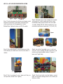
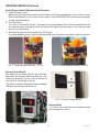
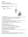
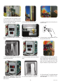
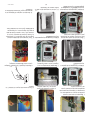
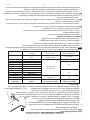
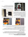
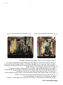
JDF-2S or JDF-4S DOOR COVER INSTALLATION
Step 1: Familiarize yourself with the circuit board switch
membrane connector layout before connecting the
switch membranes to the appropriate stations.
Chilled Water: Optional feature on JDF-4S models.
Step 3: After connecting all switch membranes to the
circuit board, place door cover over the inner door as-
sembly.
Step 5:
Finish screwing all screws down until they are
set in position (Do Not Over Tighten).
Step 6: Place flavor labels into label holders accord-
ingly to the product being placed in the cabinet per
dispense station.
Step 2: Hold door cover close enough to inner door
and connect all switch membranes to the circuit
board before door placement onto the inner door
assembly. Model JDF-2S: Switch membranes con-
nect onto circuit board connectors 1 (J2) & 2 (J3).
Step 4: Locate the 5 provided screws. Install and
start all 5 screws through the door cover holes and
into the receiving threaded weld nut (2 upper, 2
lower and 1 right side).
Upper
Station Station Station Station
1 2 3 water 4
Lower Side
2 3 41

7
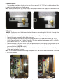
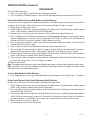
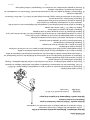
INITIAL FILL
CAUTION: The dispenser must be disconnected from the power source throughout the initial fill except when
specified in the instructions.
1. Remove drip tray assembly and splash panel from the dispenser. Replace the drip tray.
2. Connect the water source to the back of the dispenser.
3. Pull the fill tube from the dispenser, remove the plug and connect it to the dispense nozzle (Fig. 5 & 6).
4. Set the Program Switch (Fig. 7) to the ON position. (On older models without program switch, set the Dis-
pense Lockout Switch (Fig. 13) to the OFF position)
5. Connect dispenser to the power source. Press and hold the dispense button for the dispense station that the
tube is connected to for 10 seconds, until you hear the water valve turn on. (For Portion Control machines,
press and hold the PLUS/STOP switch)
6. Monitor the water bath fill level until water starts to trickle from the overflow tube. Then press the dispense
button again to stop the fill process.
NOTE: The fill timer may time out before filling is complete. Press and hold the dispense button for 10 seconds
to start again if needed.
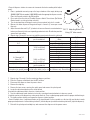
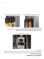
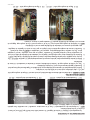
FIG 1 Plumbing Connections - JDF-2S
PLUMBING HOOKUP
The plumbing connection is located on the rear of the dispenser. A 3/8" (9.52 mm) male flare adapter fitting
is supplied, installed on the rear of the dispenser.
NOTE - Water pipe connections and fixtures directly connected to a potable water supply shall be sized, installed
and maintained in accordance with federal, state and local codes.
P3580-1
FIG 3 Initial Fill Hose - JDF-2S
FIG 2 Plumbing Connections - JDF-4S
FIG 4 Initial Fill Hose - JDF-4S
P3841
44744.2 110813

8
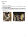
FIG 5 Initial Fill Connection - JDF-2S
7. Turn ON the refrigeration switch near the main control board (Fig. 7). This will start the water bath pump
circulation.
8. Check water level in the overflow tube and top off the tank if necessary (Step 5).
9. Disconnect the fill tube and allow excess water to drain into the drip tray. Replace the plug in the end of the
fill tube and store back into the dispenser.
10. Set the Program Switch (near main control board) to the OFF position. (On older models without program
switch, set the Dispense Lockout Switch to the ON position)
11. Replace the splash panel and drip tray.
12. It will take several hours to create the ice bank required for full dispenser performance. During this time, some
further trickling from the water bath is expected due to expansion caused by ice bank formation. While the
refrigeration system is creating the ice bank, the dispenser may be readied for use as described in Loading,
Priming and Adjustment.
INITIAL FILL (Continued)
FIG 6 Initial Fill Connection - JDF-4S
44744.2 110813

9
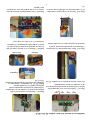
OPERATING CONTROLS
FIG 7 Refrigeration Switch
The refrigeration switch is located on the Electrical Panel of the dispenser near the Circuit Board. This switch
controls power to the water bath pump and relay contacts for the compressor and condenser fan motor.
Pressing and holding switch will initiate product flow from the respective nozzle; releasing the switch will stop
the flow.
FIG 9 Product Dispense Switches - JDF-2S FIG 10 Product Dispense Switches - JDF-4S
44744.2 110813

10
FIG 11 Product Dispense Switches - JDF-2S
Product Dispense Switch (Membrane Switch Machines)
A. Product Dispense Switch
Momentarily pressing and releasing one of the switches will initiate a timed dispense. Each station has three
different timed dispenses which are preset at the factory. Refer to DISPENSER USE section for preset volumes
and adjustment procedures.
B. Plus/Stop Switch
This switch can be used to “top-off” a beverage. Pressing and holding switch will initiate product flow from
the respective nozzle; releasing the switch will stop the flow. Momentarily pressing this switch during a timed
dispense will stop the flow.
C. Chilled Water Dispense Switch (Optional for JDF-4S only)
Pressing and holding switch will initiate chilled water flow from the nozzle; releasing the switch will stop flow.
FIG 12 Product Dispense Switches - JDF-4S
OPERATING CONTROLS (Continued)
FIG 13 Dispense Lockout Switch
Dispense Lockout Switch
Early models has the dispense On/Off switch at the bot-
tom front of the dispenser behind the drip tray. Later
model juice dispensers has the switch located on the
rear side of the cabinet door at the top.
The switch is used to disable product dispense and door
LED lights, preventing unauthorized use.
FIG 14 Program Switch
Program Switch
This switch is located near the main control board next
to the refrigeration switch.
44744.2 110813

11
OPERATING CONTROLS (Continued)
Portion Control Option (Push and Hold Membrane Switch Machines)
The dispenser is also equipped with a portion control option. The following steps will guide you through the set
up process for this option. Portion control can be set on one or all dispense heads as needed.
1. Unplug dispenser from power source.
2. Set the Program Switch (near main control board) to the ON position. (On older models without program
switch, set the Dispense Lockout Switch to the OFF position)
3. Remove drip tray and splash panel from the front of the machine then replace the drip tray.
4. Press and hold the left most (Station 1) dispense switch while plugging the dispenser into the power source.
Continue holding dispense switch(s) until all 4 temperature LED’s, Figs. 15 and 16 on the circuit board start
flashing slowly (this takes about 5 seconds). Release dispense switch(s).
5. Press and release any dispense switch 6 times to enter the portion control set up mode. This will cause the
4 temperature LED’s to flash rapidly.
6. Place a container under the desired dispense nozzle to measure the portion size.
7. Press and hold the desired dispense switch to dispense product until the desired amount of product is
achieved. (Maximum dispense time is 150 seconds). Repeat this on all dispense heads as desired.
8. Set the Program Switch (near main control board) to the OFF position. (On older models without program
switch, set the Dispense Lockout Switch to the ON position)
9. Place a container under the dispense nozzle(s) and press the dispense button to confirm that the portion size
is set correctly. Repeat steps 1-8 if any changes are needed.
10. Replace splash panel.
Note: The portion control dispense can be cancelled during a dispense by pressing the dispense button again.
Note: If a portion size is not set for a dispense head while in the portion control set up mode, that dispense head
will remain a push and hold dispense head.
Portion Control Option (Portion Control Membrane Switch Machines)
Portion sizes are preset but can be adjusted by following these steps below.
1. Set the Program Switch (near main control board) to the ON position. (On older models without program
switch, set the Dispense Lockout Switch to the OFF position)
2. Press and hold the large and medium buttons on the left most (Station #1) dispense station until you hear
the machine "beep" three times.
3. Place a measuring container under the station to be adjusted, then press and hold the appropriate dispense
switch until the desired amount is dispensed. The machine will record the amount of time that the button is
pressed continuously. If the button is released too soon, simply empty the container and start over.
4. Repeat step 3 for all stations as desired.
5. Turn the program switch to the OFF position.
DISPENSER USE
Press and Hold Dispensing:
1. Place a cup on the drip tray beneath the desired dispensing nozzle.
2. Press and hold the “Product Dispense” switch until the beverage reaches the desired level, then release.
Push and Hold Membrane Switch Machines
1. To set single portion sizes on a push and hold membrane type dispense switch, follow steps 1 - 10 above.
44744.2 110813

12
P3585
FIG 15 Temperature LEDs JDF-2S
(Early Models)
FIG 16 Temperature LEDs JDF-4S
P3845
OPERATING CONTROLS (Continued)
FIG 15A Temperature LEDs JDF-2S
(Late Models)
Procedure to return all dispense heads back to Push and Hold mode (Push and Hold Membrane Switch
Machines):
1. Unplug dispenser from power source.
2. Place Program switch in the ON position.
3. Remove drip tray and splash panel from the front of the machine then replace the drip tray.
4. For the JDF-2S, press and hold either dispense switch while plugging the dispenser into the power source.
For the JDF-4S, press and hold two left dispense switches while plugging the dispenser into the power
source. Continue holding dispense switch(s) until all 4 temperature LED’s on the circuit board start flashing
slowly (this takes about 5 seconds). Release dispense switch(s).
5. Press and release any dispense switch three times.
6. Place Program switch back into the OFF position.
7. Replace splash panel and drip tray.
8. Place a container under each dispense nozzle and press dispense buttons to confirm machine is operating
in push and hold mode.
44744.2 062912

13
CLEANING & PREVENTIVE MAINTENANCE
Daily: Rinse Procedure
Tools required: 32 oz. (946 ml) minimum empty container
1. Open dispenser door. Lift up on product containers and remove them from the machine.
2. Close the door, place an empty container under the dispensing nozzle.
3. Dispense from each station until clear water flows from the dispense nozzle.
4. Open dispenser door and reconnect all product containers.
Daily: Parts Washing
1. Remove and wash the dispense nozzle(s), drip tray and drip tray cover in a mild detergent solution. Rinse thoroughly.
Use brush (00674.0000) to clean inside and oring area on dispense nozzles.
2. Wipe splash panel, areas around dispense nozzle(s), and refrigerated compartment with a clean, damp cloth.
3. Use brush and a mild detergent solution to clean inside dispense area where dispense nozzles are removed. Rinse.
Sanitize Process for Semi-Automatic and Manual
Tools required: 1 empty 5 gallon (18.9 L) bucket, 2 packets of Kay 5 sanitizer, and clean, empty concentrate container.
1. Remove all concentrate from the dispenser and store in a separate refrigerated compartment.
2. Fill clean empty concentrate container(s) with approximately 32 oz. (946 ml) of hot tap water (approximately 140 Deg.
F (60 Deg. C). Load the containers of hot water into the dispenser (just like concentrate).
3. Place an empty container under the dispense nozzles.
4. Press and hold the dispense button at each station until the stream out of the nozzles runs clear (about 30 seconds).
Note: the dispenser will not allow all stations to run at the same time.
5. Once this is completed, remove the container(s) and empty.
6. Remove each dispense nozzle and mixing element and run under hot tap water to remove excess pulp.
7. Prepare 2.5 gal. (9.46 L) of sanitizing solution by dissolving 1 packet of Kay 5 sanitizer into 2.5 gal. (9.46 L) of 120
Deg F (48.9 Deg. C) water to ensure 100 ppm of available chlorine.
8. Place nozzle(s) and mixing element(s) in a separate 1-quart container of sanitizing solutions and mix thoroughly. Allow
the parts to soak for 2 minutes.
9. Clean the dispense nozzle receptacle(s) (dispense valves) with the sanitizing solution and a soft bristle brush.
10. Clean the concentrate bottle’s inlet adapter(s) using the sanitizing solution and a soft bristle brush.
11. Replace the mixing element(s) and nozzle(s).
12. Fill approximately 128 ounces (3.8 L) of clean sanitizing solution into clean, empty concentrate container(s). Do not
use the sanitizing solution used in step 10. Load the container(s) into the dispenser.
13. Place the empty 5 gallon bucket under the dispense nozzles.
For Semi-Automatic Sanitizing Prior to S/N JDF0016500:
14. a. For the JDF-2S, press and hold both dispense buttons for about 10 seconds to initiate the sanitize cycle.
b. For the JDF-4S, press and hold three left most dispense buttons (Stations 1, 2 and 3) for about 10 seconds to initiate
the sanitize cycle. The cycle will start with only one of the dispense stations dispensing. Note: The cycle will consist
of a 1 minute dispense time (alternating) on each station, then 5 minutes of soak time, then a 2 minute dispense time
(alternating) on each station.
For Semi-Automatic Sanitizing Effective S/N JDF0016500 and up:
14. Turn the Program Switch in the bottom of the machine to the "ON" position.
a. For the JDF-2S, press the left dispense button 2 times, then press the right dispense button 2 times.
b. For the JDF-4S, press the left most (station 1) dispense button 2 times, then the left center (station 2) button 2
times. The cycle will start with only one of the dispense stations dispensing. Note: The cycle will consist of a 1 minute
dispense time (alternating) on each station, then 5 minutes of soak time, then a 2 minute dispense time (alternating)
on each station.
For Manual Sanitizing:
14. a. Dispense each station for 1 minute.
b. Allow to soak for 5 minutes.
c. Dispense each station for 2 minutes.
NOTE: On Portion Control models, use the plus/stop switches.
15.
When the above cycle is complete, Remove the sanitizing solution and replace with concentrate.
16. At each station, press and hold the dispense switch until product appears. Then dispense one 12 ounce (354.9 ml)
glass of finished product and discard.
17. Wipe internal and external surfaces with a clean, damp cloth.
44744.2 121913

14
CLEANING (cont)
Weekly: Clean Condenser Coils and Filter
1. Removable filter can be cleaned in warm soapy water.
2. Use a soft bristle brush to clean the build up of dirt in the condenser.
Annually: Check water level in ice bath. Top off if needed.
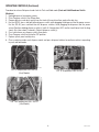
Annually: Replace Pump Tubing
1. Open dispenser door.
2. Remove all product containers and place them in a refrigerated (35-40 degrees F [1.6-4.4 degrees C]) envi-
ronment. Disconnect all connections to ambient products from the bottle adapter.
3. Rinse all dispense stations using steps outlined in “DAILY RINSE PROCEDURE”.
4. Disconnect dispenser from power source.
5. Remove the dispense platform cover.
6. Disconnect the dispense platform water line(s) from the supply line inside the refrigerated cabinet and dis-
connect the wiring connection(s) from the cabinet receptacle(s).
7. Remove the mounting screw(s) securing the dispense platform(s) to the cabinet .
8. Pull the dispense platform(s) completely out of the cabinet and place it on a flat work surface.
9. Close the dispenser door.
10. Remove the 4 screws securing the pump head.
11. Gently pull the pump head apart.
12. Gently pull the pump tube from around the pump’s rotor.
13. Release the clamps securing the old pump tubing to the plastic elbows.
14. Pull the plastic elbows from the old pump tubing, and discard the old pump tubing.
15. Insert the plastic elbows into the new pump tubing and secure it with the clamps.
16. Gently wrap the new pump tubing around the pump’s rotor.
17. Reassemble the pump housing onto the platform assembly.
18. Repeat steps 10 through 17 for the remaining pump(s).
19. Replace the dispense platform(s) into the refrigerated cabinet, making sure to reconnect all electrical and
water connections.
20. Replace the dispense platform cover.
21. Turn power on to dispenser.
22
Install containers of rinse water, run each station and check for leaks. Repair leaks as necessary.
23. Replace product shelf and product containers. Reconnect any connections to ambient product containers.
24. Prime the pumps as described in “PRIMING” in the Initial Fill Section.
39690.0000 Tube Kit JDF-2S & JDF-4S
39688.0000 Tube Assembly
44744.2 031116

15
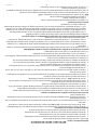
FIG 17 Adjusting Water Flow
Using 1/4" allen wrench
2+1 *3.0 fl. oz (89 ml) Prune Juice 16.0%
per 3-second test Other *
Orange Juice 11.8%
4+1 Pineapple Juice 12.8%
Cranberry Fruit Cocktail 14.0%
*3.0 fl. oz (89 ml) Grapefruit Juice 10.6%
per 3-second test Lemonade
5+1 Apple Juice 12.0%
Fruit Punch
Grape Juice 13.0%
3+1 through 7+1 Other *
Above 7+1 *4.0 fl. oz (118 ml) Other *
per 3-second test
High Viscosity Juice 3.0 fl. oz (89 ml) As Required -
per 3-second test
*Maximum flow rate may be less depending on the water pressure supply at each location.
Information for specific products listed in this table is to be used for reference only. Consult the product label for exact
mix ratio and/or brix %. See product label for target brix %.
: Purge all dispense stations to remove air from water line before making initial adjust-
ments.
1. Place a graduated measuring cup or the large chamber of the empty brixing cup
(BUNN-O-MATIC part number 33095.0000) under the appropriate dispense nozzle.
Place the Program switch in the ON position.
2. Press and release the desired “Product Dispense Switch” three times.(On Portion
Control models, use the plus/stop switches)
3. The selected position will dispense water (no concentrate) only for 3 seconds.
4. Measure the water dispensed. Suggested target is 3 ounces (1 ounce per second
flow rate.
5. Adjust the water flow rate Fig 17, (clockwise to increase flow rate; counterclockwise
to decrease flow rate) to the corresponding product mix ratio. Chart below provides
general brix instructions.
6. Repeat steps 1 through 5 as necessary until the correct water flow rate is achieved.
P3586
7. Repeat steps 1 through 5 for the remaining dispense positions.
8. Place the Program switch back into the OFF position.
1. Disconnect the dispenser from the power source.
2. Remove the drip tray.
3. Remove the two screws securing the splash panel and remove the splash panel
4. Locate the adjustment knobs on the circuit board.
Start with the adjustment dial in the nine o'clock position.
5. Turn the adjustment knobs clockwise to increase speed and counterclockwise to decrease speed.
If splashing occurs while dispensing, reduce water flow rate. Then re-adjust pump speed to achieve proper ratio/brix target.
6. The knob positions directly correspond to dispense station locations.
: Some 2S models have 4 adjustment knobs on the circuit board. For these models use the two left most knobs to make
pump speed adjustments. Left most being station #1 (left side dispense) and left center being station #2 (right side dispense).
7.
Reinstall the splash panel and drip tray and reconnect the dispenser to the power source.
44744.2 110813

16
LOADING
Frozen Concentrates
1. Thaw the frozen concentrate in a refrigerated 35-40 degrees F (1.6-4.4 degrees C) environment for 36 to 48
hours before use.
NOTE: Loading frozen concentrate in the product cabinet may cause damage to the machine. This damage is
not covered by warranty.
2. Thoroughly mix the thawed concentrate by vigorously shaking the product container.
3. Open the dispenser door.
4. Prior to placing the product container in the dispenser, make sure that the o-ring on the container adapter is
lubricated. This will ease removal of the container when it becomes necessary.
5. Place the product container in the desired position and press it firmly into the bottle adapter opening.
6. Open the vent hole in the product container.
Note: Concentrate in the container must be completely thawed and be within the temperature range of 35-40
degrees F (1.6-4.4 degrees C.) Product outside of this temperature range, especially below, will produce an “out
of brix” drink.
Ambient Concentrates (Optional)
1. Install an Ambient Concentrate Conversion Kit (BUNN-O-MATIC part number 33699.0002) per the instruc-
tions provided in the kit.
2. Attach the concentrate product hose to the appropriate concentrate line located at the rear of the dispenser.
3. Attach the other end of the product hose to the product container through an appropriate fitting.
PRIMING
1. Open the dispenser door
2. Load concentrate per instructions in section titled Loading.
3. Close the dispenser door.
4. Place a large container under the appropriate dispense nozzle.
Press and hold the “Product Dispense Switch” until concentrate dispenses from the dispense nozzle.
Note: This may take several seconds, depending on the installation and set pump speed.
44744.2 110813

17
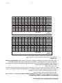
1. Adjust water flow as described in . Record water output setting for later reference on each dispense head. Suggested target
is 3 ounces.
2. Place the Program switch in the ON position.
3. Place a measuring container under the dispense nozzle, press and release the DISPENSE button 6 times.
: For best results, discard the first sample and measure a second sample. Repeat the same practice after every adjustment.
4. Record the total ounces dispensed.
5. Refer to the Brix/Ratio chart below to confirm proper total dispensed amount for ratio desired and water output previously
recorded.
6. To increase or decrease the product output, refer to section.
7. Place the Program switch back into the OFF position.
44744.2 110813
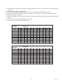
Ratio Target
2:1 3:1 4:1 5:1 6:1 7:1 8:1 9:1 10:1 11:1 12:1
1.5 2.25 2.00 1.88 1.80 1.75 1.71 1.69 1.67 1.65 1.64 1.63
1.75 2.63 2.33 2.19 2.10 2.04 2.00 1.97 1.94 1.93 1.91 1.90
2.0 3.00 2.67 2.50 2.40 2.33 2.29 2.25 2.22 2.20 2.18 2.17
2.25 3.38 3.00 2.81 2.70 2.63 2.57 2.53 2.50 2.48 2.45 2.44
2.5 3.75 3.33 3.13 3.00 2.92 2.86 2.81 2.78 2.75 2.73 2.71
2.75 4.13 3.67 3.44 3.30 3.21 3.14 3.09 3.06 3.03 3.00 2.98
3.0 4.50 4.00 3.75 3.60 3.50 3.43 3.38 3.33 3.30 3.27 3.25
3.25 4.88 4.33 4.06 3.90 3.79 3.71 3.66 3.61 3.58 3.55 3.52
3.5 5.25 4.67 4.38 4.20 4.08 4.00 3.94 3.89 3.85 3.82 3.79
3.75 5.63 5.00 4.69 4.50 4.38 4.29 4.22 4.17 4.13 4.09 4.06
4.0 6.00 5.33 5.00 4.80 4.67 4.57 4.50 4.44 4.40 4.36 4.33
3 second
water dispense
in ounces
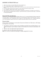
Ratio Target
2:1 3:1 4:1 5:1 6:1 7:1 8:1 9:1 10:1 11:1 12:1
44.4 66.5 59.1 55.5 53.2 51.8 50.7 49.9 49.3 48.8 48.4 48.1
51.8 77.6 69.0 64.7 62.1 60.4 59.1 58.2 57.5 56.9 56.5 56.1
59.1 88.7 78.9 73.9 71.0 69.0 67.6 66.5 65.7 65.1 64.5 64.1
66.5 99.8 88.7 83.2 79.8 77.6 76.0 74.9 73.9 73.2 72.6 72.1
73.9 110.9 98.6 92.4 88.7 86.3 84.5 83.2 82.1 81.3 80.7 80.1
81.3 122.0 108.4 101.7 97.6 94.9 92.9 91.5 90.4 89.5 88.7 88.1
88.7 133.1 118.3 110.9 106.5 103.5 101.4 99.8 98.6 97.6 96.8 96.1
96.1 144.2 128.1 120.1 115.3 112.1 109.8 108.1 106.8 105.7 104.8 104.1
103.5 155.3 138.0 129.4 124.2 120.8 118.3 116.4 115.0 113.9 112.9 112.1
110.9 166.4 147.9 138.6 133.1 129.4 126.7 124.8 123.2 122.0 121.0 120.1
118.3 177.4 157.7 147.9 141.9 138.0 135.2 133.1 131.4 130.1 129.0 128.1
3 second
water dispense
in milliliters

18
1. Adjust the water flow as described in Water Flow Testing and Adjustment.
2. Place an empty container under the appropriate dispense nozzle.
3. Press and hold the “Product Dispense Switch” Figs 9 & 10, until water and concentrate begin flowing freely from the dispense
nozzle.
4. Discard the product caught previously and place the empty container back under the dispense nozzle.
5. Press and hold the “Product Dispense Switch” until the cup is filled.
6. Stir the contents of the cup, and use the refractometer (according to the manufacturer’s instructions) to check the brix %.
7. Adjust the pump speed (down to decrease the brix %; up to increase the brix %) to achieve the correct brix % as described
in Pump Speed Adjustment.
Optional Cold Water Flow Adjustment
Some dispensers are equipped with an optional cold water dispense valve. It is recommended to adjust the flow rate upon initial
set up of the dispenser. The adjustment for the cold water can be located inside the dispenser behind the right service panel.
The cold water dispense valve is mounted to the frame just above the ice bath. Attached to this valve is a needle type adjustment
valve. Turn the adjustment clockwise to decrease the water flow, and counter-clockwise to increase the water flow.
ADJUSTMENT & OPTIONAL SETTINGS (cont)
Dispenser Lockout
Dispense functions of the dispenser can be turned-off to prevent unauthorized use of the dispenser, while keeping
the refrigeration system running.
1. Early models has the Dispense Lockout switch at the bottom front of the dispenser behind the drip tray. Later
model juice dispensers has the Dispense Lockout switch located on the rear side of the cabinet door at the
top.
2. Place the switch in the OFF position to prevent dispensing.
3. Place the switch in the ON position to allow dispensing.
NOTE: This switch will also operate the door lights on models equipped with this feature.
44744.2 082112

19
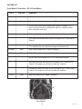
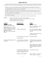
FUNCTION LIST
P3585
FIG 18 JDF-2S
(Early Models)
1
3
5
2
4
44744.2 110813
Circuit Board LED Indicators - JDF-2S (Early Models)
LED # LED Color Illuminates:
1 Green When the compressor should be ON.
2 Cabinet Red When the cabinet temperature is above 50 degrees F.
Flashes slowly when cabinet temperature exceeds 50 degrees F for 4
hours. Dispense functions are locked out under this condition. Power
down the dispenser to reset.
Flashes rapidly if dispense is attempted in lockout condition.
Open cabinet thermistor circuit will flash #2 and #3 LED’s 1 time every 3
seconds.
Shorted cabinet thermistor will turn #2 and #3 LED’s on steady.
*This mode disables the cabinet low temperature lockout fault.
3 Cabinet Green When cabinet temperature is below 50 degrees F.
4 Bath Red When bath temperature is above 34 degrees F.
Flashes slowly when compressor is in a 6 minute delay period.
Open bath thermistor circuit will flash #4 and #5 LED’s 1 time every 3
seconds. The compressor will not run under this condition.
Shorted bath thermistor circuit will flash #4 and #5 LED’s 2 times every 3
seconds. The compressor will not run under this condition.
5 Bath Green When bath temperature is below 34 degrees F.

20
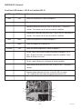
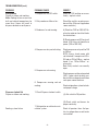
FIG 19 JDF-4S
FUNCTION LIST (Continued)
3
1
2
4
5
P3845
Circuit Board LED Indicators - JDF-4S and Late Model JDF-2S
LED # LED Color Illuminates:
1 Bath Red When bath temperature is above 34 degrees F.
Flashes slowly when compressor is in a 6 minute delay period.
Open bath thermistor circuit will flash #1 and #2 LED’s 1 time every 3
seconds. The compressor will not run under this condition.
Shorted bath thermistor circuit will flash #1 and #2 LED’s 2 times every 3
seconds. The compressor will not run under this condition.
2 Bath Green When bath temperature is below 34 degrees F.
3 Green When the compressor should be ON.
4 Cabinet Red When the cabinet temperature is above 50 degrees F.
Flashes slowly when cabinet temperature exceeds 50 degrees F for 4
hours. Dispense functions are locked out under this condition. Power
down the dispenser to reset.
Flashes rapidly if dispense is attempted in lockout condition.
Open cabinet thermistor circuit will flash #4 and #5 LED’s 1 time every 3
seconds.
Shorted cabinet thermistor will turn #4 and #5 LED’s on steady.
*This mode disables the cabinet low temperature lockout fault.
5 Cabinet Green When cabinet temperature is below 50 degrees F.
44744.2 110813
La page est en cours de chargement...
La page est en cours de chargement...
La page est en cours de chargement...
La page est en cours de chargement...
La page est en cours de chargement...
La page est en cours de chargement...
La page est en cours de chargement...
La page est en cours de chargement...
La page est en cours de chargement...
La page est en cours de chargement...
La page est en cours de chargement...
La page est en cours de chargement...
La page est en cours de chargement...
La page est en cours de chargement...
La page est en cours de chargement...
La page est en cours de chargement...
La page est en cours de chargement...
La page est en cours de chargement...
La page est en cours de chargement...
La page est en cours de chargement...
La page est en cours de chargement...
La page est en cours de chargement...
La page est en cours de chargement...
La page est en cours de chargement...
La page est en cours de chargement...
La page est en cours de chargement...
La page est en cours de chargement...
La page est en cours de chargement...
La page est en cours de chargement...
La page est en cours de chargement...
La page est en cours de chargement...
La page est en cours de chargement...
La page est en cours de chargement...
La page est en cours de chargement...
La page est en cours de chargement...
La page est en cours de chargement...
La page est en cours de chargement...
La page est en cours de chargement...
La page est en cours de chargement...
La page est en cours de chargement...
La page est en cours de chargement...
La page est en cours de chargement...
La page est en cours de chargement...
La page est en cours de chargement...
La page est en cours de chargement...
La page est en cours de chargement...
La page est en cours de chargement...
La page est en cours de chargement...
-
 1
1
-
 2
2
-
 3
3
-
 4
4
-
 5
5
-
 6
6
-
 7
7
-
 8
8
-
 9
9
-
 10
10
-
 11
11
-
 12
12
-
 13
13
-
 14
14
-
 15
15
-
 16
16
-
 17
17
-
 18
18
-
 19
19
-
 20
20
-
 21
21
-
 22
22
-
 23
23
-
 24
24
-
 25
25
-
 26
26
-
 27
27
-
 28
28
-
 29
29
-
 30
30
-
 31
31
-
 32
32
-
 33
33
-
 34
34
-
 35
35
-
 36
36
-
 37
37
-
 38
38
-
 39
39
-
 40
40
-
 41
41
-
 42
42
-
 43
43
-
 44
44
-
 45
45
-
 46
46
-
 47
47
-
 48
48
-
 49
49
-
 50
50
-
 51
51
-
 52
52
-
 53
53
-
 54
54
-
 55
55
-
 56
56
-
 57
57
-
 58
58
-
 59
59
-
 60
60
-
 61
61
-
 62
62
-
 63
63
-
 64
64
-
 65
65
-
 66
66
-
 67
67
-
 68
68


Bunn JDF-2S Guide d'installation
- Catégorie
- Cafetières
- Taper
- Guide d'installation
- Ce manuel convient également à
dans d''autres langues
- English: Bunn JDF-2S Installation guide
Documents connexes
-
Bunn JDF-4S Lit Door Guide d'installation
-
-
Bunn JDF-4S Lit Door Guide d'installation
-
Bunn NITRON® Cold Draft Scholle 4:1 to 12:1 Guide d'installation
-
Bunn iMIX-5 Black TH/Hot Water Guide d'installation
-
Bunn H10X-80-208 Guide d'installation
-
-
Bunn ULTRA-2 HPR GP,BLK LED GOURMET-EXT HDL Guide d'installation
-
-