NAPOLEON BIPF450 Le manuel du propriétaire
- Taper
- Le manuel du propriétaire

BUILT-IN PF UNIT INSTRUCTION GUIDE
Please use this manual in conjuction with your main manual to properly assemble your built-in grill. Refer to
the main manual for operating, cleaning, and maintenance instructions. The operating instructions are also
located on the bottom of the side burner lid. This grill is designed for NON-COMBUSTIBLE ENCLOSURES
ONLY, and must be installed and serviced by a qualified installer to local codes.
BUILT IN PROPANE GAS HOOK-UP: The piping up to the gas grill is the responsibility of the installer and
piping should be located as shown in the built-in instructions. Do not use hose to connect the unit. It must be
connected with either rigid pipe, copper tube or an approved flexible metal connector. The installation must
comply with CAN B149.1 Natural Gas and Propane Installation Code in Canada, or to the National Fuel Gas
Code, ANSI Z223.1 in the United States. The minimum recommended piping size is NPS 1/2" for rigid pipe,
and 5/8" OD for copper tubing (based on a 20 ft run). Longer runs may require larger sizes to conform with
local codes or to conform with CAN B149.1. Propane Gas Installation Code in Canada or to the National Fuel
Gas Code, ANSI Z223.1 in the United States. If the enclosure is to house a propane cylinder, the tank portion
of the enclosure must be ventilated according to local codes, and must not have communication with the cavity
used to enclose the gas grill. The tank can not be stored below the gas grill.
BUILT IN NATURAL GAS HOOK-UP: The piping up to the gas grill is the responsibility of the installer and
piping should be located as shown in the built-in instructions. Do not use hose to connect the unit. It must be
connected with either rigid pipe, copper tube or an approved flexible metal connector. The installation must
comply with CAN B149.1 Natural Gas and Propane Installation Code in Canada, or to the National Fuel Gas
Code, ANSI Z223.1 in the United States. The minimum recommended piping size is NPS 1/2" for rigid pipe,
and 3/4" OD for copper tubing (based on a 20 ft run). Longer runs may require larger sizes to conform with
local codes or to conform with CAN B149.1. Natural Gas Installation Code in Canada or to the National Fuel
Gas Code, ANSI Z223.1 in the United States.
Built in units are supplied with a drip pan which holds only a minimal amount of grease. To prevent
grease fires, the pan must be cleaned after each use. Access must be provided to the inside of the
enclosure to make gas connections.
SERIAL #
DANGER: READ ALL INSTRUCTIONS CAREFULLY BEFORE OPERATING GRILL. FAILURE TO FOL-
LOW THESE INSTRUCTIONS EXACTLY COULD RESULT IN A FIRE CAUSING SERIOUS INJURY OR
DEATH.
N415-0111 / JUNE 21//07

ELECTRICAL BOX
OPENING
8 7/8”
20 5/8”
7”
8 ¼”
8 ¼”
34”
RECOMMENDED
4”
6”
55 ¾” PF600 UNITS
46 ¾” PF450 UNITS
2” MIN
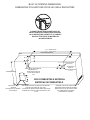
CENTER OF ELECTRICAL BOX MUST BE WITHIN 3
FEET OF LEFT EDGE OF GAS GRILL
ELECTRICAL WIRE ACCESS
OPENING (4”x4”)
GAS INLET OPEN-
ING (4”x4”)
MINIMUM 10 SQ IN OF VENTILATION
REQUIRED ON EACH END OF CABINET
NON COMBUSTIBLE MATERIAL
CABINET FRAME AND CABINET MUST BE
MADE FROM NON-COMBUSTIBLE MATERIAL
BUILT-IN OPENING DIMENSIONS
LA CHARPENTE DU CABINET ET LE CABINET
DOIVENT ÊTRE FAITS DE MATÉRIAUX
INCOMBUSTIBLES
DIMENSIONS D’OUVERTURE POUR LES GRILS ENCASTRÉS
OUVERTURE DU BOÎTIER
ÉLECTRIQUE
LE CENTRE DU BOÎTIER ÉLECTRIQUE DOIT ÊTRE
À MOINS DE 3 PIEDS DU CÔTÉ GAUCHE DU GRIL
À GAZ
OUVERTURE POUR LE
FILAGE ÉLECTRIQUE
4”x4”
MINIMUM DE 10 PO² DE VENTILATION
EST NÉCESSAIRE À CHAQUE
EXTRÉMITÉ DU CABINET
OUVERTURE
POUR LA
CONDUITE DE GAZ
(4” x 4”)
MATÉRIAU INCOMBUSTIBLE

H
W
D
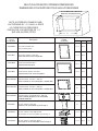
NOTE: ACCESSORY FRAMES OVER-
LAP OPENING BY 1 ½” ON ALL 4 SIDES
Part #
Description
Picture
WH
N370-0070
Flat horizontal painted door
N370-0357SS
N370-0358SS
13 ¼”
18 ¼”
OPENING DIMENSION
N370-0356SS Curved stainless steel door - 308 size
N370-0072
Flat horizontal stainless steel door
N370-0069 Flat vertical painted door
N370-0071
Flat vertical stainless steel door
Curved stainless steel door - 450 size
Curved stainless steel double door - 600 size
N370-0361 PF style stainless steel door
N370-0359 PF style stainless steel single drawer
N370-0360 PF style stainless steel triple drawer
13 ¼” 18 ¼”
18 ¼” 13 ¼”
18 ¼” 13 ¼”
22 ½” 19 ¾”
27” 19 ¾”
17”
23 ¼”
17 ¼” 6 ¾”
17 ¼” 22 ¾”
BUILT-IN ACCESSORY OPENING DIMENSIONS
35 ¼” 19”
23”
23”
D
NON COMBUSTIBLE MATERIAL
LE CADRE DES ACCESSOIRES
CHEVAUCHE L’OUVERTURE DE 1 ½”
SUR LES QUATRE CÔTÉS.
DIMENSIONS D’OUVERTURE POUR LES ACCESSOIRES
N° de pièce Illustration
Porte horizontale peinte
Porte cambrée en acier inoxydable - modèle 308
Porte horizontale en acier inoxydable
Porte verticale peinte
Porte verticale en acier inoxydable
Porte cambrée en acier inoxydable - modèle 450
Porte cambrée double en acier inoxydable
- modèles 600/750
Porte en acier inoxydable style Prestige V
Tiroir simple en acier inoxydable style Prestige V
Tiroir triple en acier inoxydable style Prestige V
MATÉRIAU INCOMBUSTIBLE

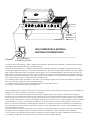
1. Lower the unit into the opening. Feed the wiring harness through the opening on the left hand side. Feed the gas flex connector
and regulator down through the opening on the right hand side.
2. Remove the electrical box cover. Install the electrical box into the opening (fasteners not included). Feed the three white wires
coming from the grill head into the hole in the back of the electrical box. Ensure the snap bushing is inserted into the hole. Feed the
black electrical cord from the inside out through the same bushing. If you are hard wiring directly to the GFI outlet, disconnect the
black electrical cord supplied and use the same terminals on the GFI to connect the hard wiring. Attach the white wires to the trans-
former output. The two wires marked T2 to one output, and the one wire marked T1, to the other output. Re-install the electrical box
cover. Plug the power cord into a suitable GFI protected outdoor outlet.
3. For natural gas units, mount the regulator to the cabinet. Connect the gas supply to the inlet side of the regulator. For propane
units, connect the gas supply to the end of the flexible connector.
4. If using the optional trim kit, install the rear and side trim pieces using a dab of silicone.
5. Leak test the entire installation before operating the unit.
N570-0046
TRIM KIT
N370-0362
ELECTRICAL BOX
NON COMBUSTIBLE MATERIAL
ENSEMBLE DE
MOULURES
BOÎTIER ÉLECTRIQUE
MATÉRIAU INCOMBUSTIBLE
1. Placez l’appareil dans l’ouverture. Passez le harnais de fils par l’ouverture sur le côté gauche. Acheminez le raccord flexible et le
régulateur vers le bas en passant par l’ouverture sur le côté droit.
2. Retirez le couvercle du boîtier électrique. Installez le boîtier électrique dans l’ouverture (pièces de fixation non comprises).
Acheminez les trois fils blancs provenant de la cuve de gril dans le trou à l’arrière du boîtier électrique. Assurez-vous que la bague
soit insérée dans le trou. Passez le cordon électrique noir de l’intérieur vers l’extérieur à travers la même bague. Si vous câblez le
cordon électrique directement à la prise avec interrupteur de défaut à la terre, débranchez le cordon électrique noir fourni et utilisez
les mêmes bornes sur la prise avec interrupteur de défaut à la terre pour câbler le cordon électrique. Fixez les fils blancs aux
bornes de sortie du transformateur. Les deux fils blancs identifiés T2 à une borne de sortie et le fil identifié T1 à l’autre borne de
sortie. Réinstallez le couvercle du boîtier électrique. Branchez le cordon d’alimentation dans une prise extérieure adéquate avec
interrupteur de défaut à la terre.
3. Pour les appareils alimentés au gaz naturel, fixez le régulateur au cabinet. Branchez l’alimentation en gaz sur le côté d’arrivée
du régulateur. Pour les appareils alimentés au propane, branchez l’alimentation en gaz à l’extrémité du raccord flexible.
4. Si vous utilisez l’ensemble de moulures optionnel, installez les moulures latérales et arrière en appliquant un peu de silicone.
5. L’installation complète doit être vérifiée pour des fuites avant de faire fonctionner l’appareil.

1. Unpack the drawer frame assembly.
2. Remove the drawers from the enclosure by fully extending them and then lifting up to remove them from the
slides.
3. Shim the opening to ensure that the enclosure fits snuggly into the opening. Ensure that the side shims are
located at the same height as the enclosure mounting holes. The bottom of the opening may need to be
shimmed as well to ensure that the front of the enclosure is plumb.
4. Once the enclosure is level and square, fasten into place. (Fasteners not included).
5. Re-install the drawers by tipping the back of the drawer down into the slide. Once the wheels are inserted
into the slide, lower the front of the drawer until it is level, then push in. Note: if the enclosure is installed with
shims that are too thick, the wheel will not engage into the slide. The shim thickness will need to be reduced.
6. Remove the protective coating from all remaining surfaces.
1. Unpack the door and frame.
a. For the curved stainless steel single doors, remove the door from the frame by lifting the door while holding
on to the pivot rod. This will allow the pivot rod to come out of the hole on the bottom of the frame.
b. For the curved stainless steel double doors, with the door in the open position, simply lift the doors off of the
hinges.
c. For the PF style stainless steel door, the door needs to be removed by loosening the center philips screw on
the hinge furthest away from the door. This will allow the hinge to separate.
2. Center the frame in the opening. Starting with the hinged side, shim between the frame and side wall of the
opening. Ensure the shims are close to the hinge on the PF style doors. When the frame side wall is plumb,
fasten it to the cabinet with screws (not provided). Attach the other side of the frame in the same fashion,
ensuring the frame is square.
3. Other than on the curved stainless steel double door kit, fasteners are not required on the top and bottom of
the frame. The curved stainless steel double door frame must be fastened in the center both at the top and
bottom.
4. Once the frame has been secured and checked for squareness, the door can be re-installed.
5. Remove the protective coating from all remaining surfaces.
BUILT-IN ACCESSORY DRAWER INSTRUCTIONS
BUILT-IN ACCESSORY DOOR INSTRUCTIONS
-
 1
1
-
 2
2
-
 3
3
-
 4
4
-
 5
5


NAPOLEON BIPF450 Le manuel du propriétaire
- Taper
- Le manuel du propriétaire
dans d''autres langues
- English: NAPOLEON BIPF450 Owner's manual
Documents connexes
-
Napoleon Grills Gourmet Grill Manuel utilisateur
-
NAPOLEON BIPF600 Le manuel du propriétaire
-
Napoleon Grills BISZ300 Manuel utilisateur
-
-
NAPOLEON BILEX485NSS-1 Le manuel du propriétaire
-
NAPOLEON BIM485 Le manuel du propriétaire
-