
JENN-AIRTM ICEMAKER/
F/_.BRICADEHIELOJENN-AIR'"/
MACHINE._.GLA(_ONSJENN-AIRTM
USE& CAREGUIDE
For questions about features, operation/performance, parts, accessories, or service, call:
1-800-JENNAIR (1-800-536-6247) or visit our website at www.jennair.com.
In Canada, call: 1-800-807-6777, or visit our website at www.jennair.ca.
MANUAL DEUSOY CUIDADO
Si tiene preguntas respecto alas caracterfsticas, funcionamiento, rendimiento, partes, accesorios o servicio tecnico, Ilame al:
1-800-JENNAIR (1-800-536-6247} o visite nuestro sitio de internet: www.jennair.com.
En CanadA, Ilame al: 1-800-807-8777, o visite nuestro sitio de internet: www.jennair.ca.
GUIDED'UTILISATIONETD'ENTRETIEN
Au Canada, pour assistance, installation ou service, composez le 1-800-807-6777 ou visitez notre site web & www.jennair.ca.
Table of Contents/lndice/Table des matieres ...................................................................................... 2
_]ENN-AIRTo
W1013612gA

TABLEOF CONTENTS
ICE MAKER SAFETY ...................................................................... 3
INSTALLATION INSTRUCTIONS .................................................. 3
Tools and Parts ............................................................................ 3
Custom Panel Dimensions ........................................................... 3
Unpack the Ice Maker .................................................................. 4
Location Requirements ................................................................ 4
Electrical Requirements ............................................................... 5
Water Supply Requirements ........................................................ 5
Leveling ........................................................................................ 5
Connect Water Supply ................................................................. 6
Drain Connection ......................................................................... 7
Install Custom Overlay Panel ....................................................... 7
Ice Maker Door ............................................................................. 8
Normal Sounds ............................................................................ 9
ICE MAKER USE........................................................................... 10
How Your Ice Maker Works ....................................................... 10
Using the Controls ...................................................................... 10
ICE MAKER CARE ........................................................................ 11
Cleaning ...................................................................................... 11
Vacation and Moving Care ......................................................... 13
TROUBLESHOOTING .................................................................. 13
Ice Maker Operation ................................................................... 13
Ice Production ............................................................................ 14
Ice Quality ................................................................................... 14
Plumbing Problems .................................................................... 14
ASSISTANCE OR SERVICE ......................................................... 15
In the U.S.A................................................................................ 15
In Canada ................................................................................... 15
WAR RANTY .................................................................................. 16
INDICE
SEGURIDAD DE LA FABRICA DE HIELO .................................. 17
INSTRUCCIONES DE INSTALACION ......................................... 17
Herramientas y piezas ................................................................ 17
Dimensiones del panel hecho a la medida ................................ 17
Desempaque la fabrica de hielo ................................................ 18
Requisitos de ubicaci6n ............................................................. 18
Requisites electricos .................................................................. 19
Requisitos del suministro de agua ............................................. 19
Nivelaci6n ................................................................................... 19
Conexion del suministro de agua .............................................. 20
Conexi6n del desagOe ............................................................... 21
Instale el panel de revestimiento hecho a la medida ................ 22
Puerta de la fabrica de hielo ...................................................... 23
Sonidos normales ...................................................................... 24
USO DE SU FABRICA DE HIELO ................................................ 25
C6mo funciona su fabrica de hielo ............................................ 25
Use de los controles .................................................................. 25
CUIBABO BE SU FABRICA DE HIELO ....................................... 26
Limpieza ..................................................................................... 26
Cuidado durante las vacaciones y mudanzas ........................... 28
SOLUCION DE PROBLEMAS ...................................................... 2g
Funcionamiento de la fbbrica de hielo ................................... 2g
Producci6n de hielo ................................................................... 29
Calidad del hielo ......................................................................... 30
Problemas de plomerfa .............................................................. 30
AYUDA O SERVICIO TECNICO ................................................... 31
En los EE.UU.............................................................................. 31
En Canada .................................................................................. 31
GARANTJA .................................................................................... 32
TABLEDESMATIERES
S¢CURITI :!:DE LA MACHINE ._.GLAQONS ................................ 33
INSTRUCTIONS D'INSTALLATION ............................................ 33
Outillage et pieces ...................................................................... 33
Dimensions du panneau personnalise ....................................... 33
Deballage de la machine a gla(;ons ........................................... 34
Exigences d'emplacement ......................................................... 34
Specifications electriques .......................................................... 35
Specifications de I'alimentation en eau ..................................... 35
Nivellement ................................................................................. 35
Raccordement a la canalisation d'eau ...................................... 36
Raccordement au conduit d'evacuation ................................... 37
Installation du panneau decoratif personnalise ......................... 38
Porte de la machine a glagons .................................................. 38
Sons normaux ............................................................................ 40
UTILISATION DE LA MACHINE ._ GLAQONS ............................ 40
Fonctionnement de la machine a gla(;ons ................................. 40
Utilisation des commandes ........................................................ 41
ENTRETIEN DE LA MACHINE ._,GLAQONS .............................. 41
Nettoyage ................................................................................... 41
Precautions a prendre avant les vacances
ou un demenagement ................................................................ 43
DC:PANNAGE ................................................................................. 44
Fonctionnement de la machine a gla(;ons ................................. 44
Production de glat_ons ............................................................... 45
Qualite des gla(;ons .................................................................... 45
Problemes de plomberie ............................................................ 45
ASSISTANCE OU SERVICE ......................................................... 46
Aux Ctats-Unis ............................................................................ 46
Au Canada .................................................................................. 46
GARANTIE ..................................................................................... 47

ICEMAKERSAFETY
Your safety and the safety of others are very important.
We have provided many important safety messages in this manual and on your appliance. Always read and obey all safety
messages.
This is the safety alert symbol.
This symbol alerts you to potential hazards that can kill or hurt you and others.
All safety messages will follow the safety alert symbol and either the word "DANGER" or "WARNING."
These words mean:
You can be killed or seriously injured if you don't immediately
follow instructions.
You can be killed or seriously injured if you don't follow
instructions.
All safety messages will tell you what the potential hazard is, tell you how to reduce the chance of injury, and tell you what can
happen if the instructions are not followed.
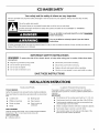
IMPORTANT SAFETY INSTRUCTIONS
WARNING: To reduce the risk of fire, electric shock, or injury when using your ice maker, follow these basic
precautions:
• Plug into a grounded 3 prong outlet.
• Do not remove ground prong.
• Do not use an adapter.
• Do not use an extension cord.
• Disconnect power before cleaning.
• Disconnect power before servicing.
• Replace all parts and panels before operating.
• Use two or more people to move and install ice maker.
SAVE THESE INSTRUCTIONS
INSTALLATIONINSTRUCTIONS
TOOLS NEEDED:
Gather the required teeis and parts befere starting instailatien.
Read and follow the instructions provided with any tools listed
here.
• Cordless drill • Masking tape
• Phillips screwdriver • Tape measure
• Router or planer • Towel or piece of
cardboard
• Pencil
PARTS NEEDED:
Custom Overlay Door Panel--See "Custom Panel Installation
Instructions," #8 x 1/2"pan head wood screws (8)
PARTS SUPPLIED:
• Adhesive pads (4)
If you plan to install a custom overlay panel, you will need to
create the panel yourself or consult a qualified cabinetmaker or
carpenter.
IMPORTANT:
• The thickness of the overlay panel must be %" (1.91 cm).
• Overlay panel must not weigh more than 8 Ibs (3.62 kg).
• Overlay panels weighing more than recommended may
cause damage to your ice maker.
• Match woodgrain direction with that of adjacent cabinets.
• Sand panel edges to provide a smooth finish.
• Use moisture sealer on both sides and all edges of the
panel to provide moisture protection.

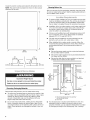
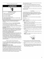
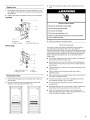
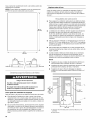
Createthecustomoverlaypanelusingthedimensionsshown.
NOTE:Thepanelmustbepreparedasshowntoallowproper
clearanceforthedoor.
2931/64''
(74,9 cm)
-_ ................................................................................................................................................................1433/64''...................................................................................................................J.-
(36,9 cm)
11/4" / _ 11/4'_]
(3,18 cm) (3,19 cm)
1/4. _-[ _(1.91 cm) (1.91 crn)l "JJJ_- 1/4.
(6,35 ram) '_ 12L (6,35 ram)
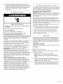
Excessive Weight Hazard
Use two or more people to move and install ice maker.
Failure to do so can result in back or other injury.
Removing Packaging Materials
Remove tape and glue from your ice maker before using.
• To remove any remaining tape or glue from the exterior of the
ice maker, rub the area briskly with your thumb. Tape or glue
residue can also be easily removed by rubbing a small
amount of liquid dish soap over the adhesive with your
fingers. Wipe with warm water and dry.
Do not use sharp instruments, rubbing alcohol, flammable
fluids, or abrasive cleaners to remove tape or glue. Do not
use chlorine bleach on the stainless steel surfaces of the ice
maker. These products can damage the surface of your ice
maker.
Cleaning Before Use
After you remove all of the packaging materials, clean the inside
of your ice maker before using it. See the cleaning instructions in
the "Ice Maker Care" section.
To ensure proper ventilation for your ice maker, the front side
must be completely unobstructed. The unit may be closed-in
on the top and three sides, but the installation should allow
the ice maker to be pulled forward for servicing if necessary.
Installation of the ice maker requires a cold water supply inlet
of W' (6.35 mm) OD soft copper tubing with a shutoff valve
and either a gravity-drain system or condensate pump to
carry the water to an existing drain.
Choose a well ventilated area with temperatures above 55°F
(13°C) and below 110°F (43°C). Best results are obtained
between 70°F (21°C) and 90°F (32°C).
This unit must be installed in an area protected from the
elements, such as wind, rain, water spray, or drip.
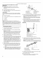
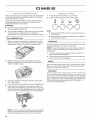
When installing the ice maker under a counter, follow the
recommended opening dimensions shown. Place electrical
and plumbing fixtures in the recommended location as
shown.
NOTES:
• Be sure the power supply cord is not pinched between
the ice maker and the cabinet.
• Be sure the water supply line is not pinched between the
ice maker and the cabinet.
• Be sure the drain line (on some models) is not pinched
between the ice maker and the cabinet.
34"
(86.4 cm)
Min.
341/2"
(87.6 cm)
Max,
281/2''
(72,4 cm)
J-'_ 15" "_
(39.1 cm)
A. Recommended location forelectrical
andplumbing fixtures
B.Floor level
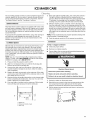
You should choose a location where the floor is even. It is
important for the ice maker to be level in order to work
properly. If needed, you can adjust the height of the ice maker
by changing the height of the leveling legs. See "Leveling."

Electrical Shock Hazard
Plug into a grounded 3 prong outlet.
Do not remove ground prong.
Do not use an adapter.
Do not use an extension cord.
Failure to follow these instructions can result in death,
fire, or electrical shock.
Before you move your ice maker into its final location, it is
important to make sure you have the proper electrical
connection:
A 115 Volt, 60 Hz., AC only, 15- or 20-amp electrical supply,
properly grounded in accordance with the National Electrical
Code and local codes and ordinances, is required.
It is recommended that a separate circuit, serving only your ice
maker, be provided. Use a receptacle which cannot be turned off
by a switch or pull chain.
IMPORTANT: If this product is connected to a GFCI (Ground
Fault Circuit Interrupter) protected outlet, nuisance tripping of the
power supply may occur, resulting in loss of cooling. Ice quality
may be affected. If nuisance tripping has occurred, and if the
condition of the ice appears poor, dispose of it.
Recommended grounding method
For your personal safety, this appliance must be grounded. This
appliance is equipped with a power supply cord having a 3 prong
grounding plug. To minimize possible shock hazard, the cord
must be plugged into a mating, 3 prong, grounding-type wall
receptacle, grounded in accordance with the National Electrical
Code and local codes and ordinances. Ifa mating wall receptacle
is not available, it is the personal responsibility of the customer to
have a properly grounded, 3 prong wall receptacle installed by a
qualified electrician.
A cold water supply with water pressure of between 30 and
120 psi (207 and 827 kPa) is required to operate the ice maksn If
you hays questions about your water pressure, call a licensed,
qualified plumber.
Reverse Osmosis Water Supply
IMPORTANT: The pressure of the water supply coming out of a
reverse osmosis system going to the water inlet valve of the ice
maker needs to be between 30 and 120 psi (207 and 827 kPa).
If a reverse osmosis water filtration system is connected to your
cold water supply, the water pressure to the reverse osmosis
system needs to be a minimum of 40 to 60 psi (276 to 414 kPa).
The reverse osmosis system must provide 1gal. (3.79 L) of water
per hour to the ice maker for proper ice maker operation.
If the water pressure to the reverse osmosis system is less than
40 to 60 psi (276 to 414 kPa):
• Check to see whether the sediment filter in the reverse
osmosis system is blocked. Replace the filter if necessary.
• Allow the storage tank on the reverse osmosis system to refill
after heavy usage.
If you have questions about your water pressure, call a licensed,
qualified plumber.
It is important for the ice maker to be level in order to work
properly. Depending upon where you install the ice maker, you
may need to make several adjustments to level it. You may also
use the leveling legs to lower the height of the ice maker for
undercounter installations.
Tools needed:
Gather the required tools and parts before starting installation.
• 9" level
• Adjustable wrench
NOTE: It is easier to adjust the leveling legs if you have another
person to assist you.
1. Move the ice maker to its final location.
NOTE: If this is a built-in installation, move the ice maker as
close as possible to the final location.
2. Place the level on top of the product to see if the ice maker is
level from front to back and side to side.
3. Push up on the top front of the ice maker, and then locate the
leveling screws that are on the bottom front of the ice maker.
4. Using an adjustable wrench, change the height of the legs as
follows:
• Turn the leveling leg to the right to lower that side of the
ice maker.
• Turn the leveling leg to the left to raise that side of the ice
maker.
NOTE: The ice maker should not wobble. Use shims to add
stability when needed.
5. Push up on the top rear of the ice maker and locate the
leveling legs that are on the bottom rear of the ice maker.
6. Follow the instructions in Step 4 to change the height of the
legs.
7. Use the level to recheck the ice maker to see that it is even
from front to back and side to side. Ifthe ice maker is not
level, repeat steps 2 to 5. If the ice maker is level, go to the
"Connect Water Supply" section.

Read all directions thoroughly before you begin.
IMPORTANT:
• Plumbing shall be installed in accordance with the
International Plumbing Code and any local codes and
ordinances.
• Use copper tubing and check for leaks.
• Install copper tubing only in areas where temperatures will
remain above freezing.
Tools needed:
Gather the required tools and parts before starting installation.
Read and follow the instructions provided with any tools listed
here.
• Flat-blade screwdriver
• 7A6"and 1/2"open-end wrenches or two adjustable wrenches
• 1/4"nut driver
• ¼" drill bit
• Cordless drill
NOTE: Your ice maker dealer has a kit available with a 1/4"
(6.35 mm) saddle-type shutoff valve, a union, and copper tubing.
Before purchasing, make sure a saddle-type valve complies with
your local plumbing codes. Do not use a piercing-type or s/16"
(4.76 mm) saddle valve which reduces water flow and clogs more
easily.
Connecting the water line
1.
2.
Turn off main water supply. Turn on nearest faucet long
enough to clear line of water.
Find a 1/2"(12.70 mm) to 11/4'' (3.18 cm) vertical cold water
pipe near the ice maker.
NOTE: Horizontal pipe will work, but the following procedure
must be followed: Drill on the top side of the pipe, not the
bottom. This will help keep water away from the drill. This
also keeps normal sediment from collecting in the valve.
3. Using a cordless drill, drill a 1/4"(6.35 mm) hole in the cold
water pipe you have selected.
4. Fasten shutoff valve to cold water pipe with pipe clamp. Be
sure outlet end is solidly in the 1/4"(6.35 mm) drilled hole in the
water pipe and that the washer is under the pipe clamp.
Tighten packing nut. Tighten the pipe clamp screws slowly
and evenly so washer makes a watertight seal. Do not
overtighten the pipe clamp or you may crush cold water pipe
if it is soft copper tubing. Do not use a piercing-type or 3/16"
(4.76 mm) saddle-type valve which reduces water flow and
clogs more easily.
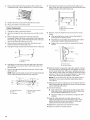
5. Now you are ready to connect the copper tubing. Use 1/4"
(6.35 mm) OD soft copper tubing for the cold water supply.
• Ensure that you have the proper length needed for the
job. Be sure both ends of the copper tubing are cut
square.
• Slip compression sleeve and compression nut on copper
tubing as shown. Insert end of tubing into outlet end
squarely as far as it will go. Screw compression nut onto
outlet end with adjustable wrench. Do not overtighten.
H,_ ................AB ..........C
A.Cold waterpipe E.Compression nut
B.Pipe clamp F.Compression sleeve
C.Copper tubing G.Shutoff valve
D.Coupling (purchased) H.Packing nut
6.
Place the free end of the tubing into a container or sink, and
turn on main water supply and flush out tubing until water is
clear. Turn off shutoff valve on the water pipe.
NOTE: Always drain the water line before making the final
connection to the inlet of the water valve to avoid possible
water valve malfunction.
7.
Bend the copper tubing to meet the water line inlet which is
located on the back of the ice maker cabinet as shown.
Leave a coil of copper tubing to allow the ice maker to be
pulled out of the cabinet or away from the wall for service.
REAR VIEW
B
C
@
D
8.
A. Water supply tube clamp
B. Vent hose (drain pump models only)
C. Water supply line
D. Inlet water tube clamp
E.Drain hose (drain pump models only)
Thread the nut onto the coupling on the end of the copper
tubing. Tighten the nut by hand. Then tighten it with a wrench
two more turns. Do not overtighten.
NOTE: To avoid rattling, be sure the copper tubing does not
touch the cabinet's side wall or other parts inside the cabinet.
A B C
A. Line to ice maker
B.Nut (purchased)
C. Ferrule(purchased)
D. Coupling (purchased)
D E F G
E.Ferrule
F. Nut
G.Supplied line from ice maker
9. Install the water supply tube clamp around the water supply
line to reduce strain on the coupling.
10. Turn shutoff valve ON.
11. Check for leaks. Tighten any connections (including
connections at the valve) or nuts that leak.

[}(_ t _7_s_ ,
Gravity Drain System
Connect the ice maker drain to your drain in accordance with all
state and local codes and ordinances. If the ice maker is
provided with a gravity drain system, follow these guidelines
when installing drain lines. This will help keep water from flowing
back into the ice maker storage bin and potentially flowing onto
the floor causing water damage.
• Drain lines must have a minimum of %" (15.88 mm) inside
diameter.
• Drain lines must have a 1" drop per 48" (2.54 cm drop per
122 cm) of run or _/4"drop per 12" (6.35 mm per 30.48 cm) of
run and must not have low points where water can settle.
• The floor drains must be large enough to accommodate
drainage from all drains.
The ideal installation has a standpipe with a 1//2" (3.81 cm) to
2" (5.08 cm) PVC drain reducer installed directly below the
outlet of the drain tube as shown. You must maintain a
1" (2.54 cm) air gap between the drain hose and the
standpipe.
• It may be desirable to insulate the drain line thoroughly up to
the drain inlet.
SIDE VIEW
I
-I
I i
!"
(4.8 cm)
I
23" C
(58,4 cm)
D
2" - 1V2"
(5 cm- 3.8 cm)
A. Drain hose
B. 1" (2.54 cm) air gap
C. PVC drain reducer
D. Center of drain should be 23" (58.4 cm) from front of door,
with or without the s/4"(1.91 cm) panel on the door. The
drain should also be centered from left to right (7_6"
[18.56 cm] from either side of the ice maker).
Drain Pump System (on some models)
Connect the ice maker drain to your drain in accordance with the
International Plumbing Code and any local codes and
ordinances.
NOTE: If the drain hose becomes twisted and water cannot
drain, your ice maker will not work.
Connecting the Drain
After ensuring that the drain system is adequate, follow these
steps to properly place the ice maker:
Electrical Shock Hazard
Plug into a grounded 3 prong outlet.
Do not remove ground prong.
Do not use an adapter.
Do not use an extension cord,
Failure to follow these instructions can result in death,
fire, or electrical shock.
1. Plug ice maker into a grounded 3 prong outlet.
Excessive Weight Hazard
Use two or more people to move and install ice maker.
Failure to do so can result in back or other injury.
2. Style I - For gravity drain system, push the ice maker into
position so that the ice maker drain tube is positioned over
the PVC drain reducer. See "Gravity Drain System" earlier in
this section. Style 2 - For drain pump system connect the
drain pump outlet hose to the drain. See "Drain Pump
System" earlier in this section.
3. Recheck the ice maker to be sure that it is level. See
"Leveling."
4. If it is required by your local sanitation code, seal the cabinet
to the floor with an approved caulking compound after all
water and electrical connections have been made.
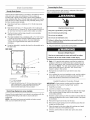
IMPORTANT: Create custom overlay panel according to the
specifications in the "Custom Overlay Panel" section.
1. Install the ice maker.
2. Level the ice maker. See "Leveling."
3. Place the ice maker under the cabinet so that the front edge
of the custom panel will align with the front edge of the
surrounding cabinets.
4. Hold the custom panel up to the ice maker and check that the
opening and alignment are correct, Mark location of the panel
as necessary.
5. Remove the tape from the face of the door.
6. Remove the paper backing from the adhesive pads that are
located on the door front.
7. Place the panel on the door, align with markings and apply
pressure in the area of the adhesive pads.
8. Check to see that the ice maker door opens and closes
properly.

9. Pulltheicemakerforwardtoaccessthetopandsidesofthe
door.
10.Removethegasketsfromtheinteriordoorpanelandset
aside.
11.Usingthefactorydrilledholesasaguide,useascribeand
markthedrillinglocationsontheoverlaypanel.
12.Drilleight1/s"x1/2"(3.18mmx12.7mm)deepholesintothe
overlaypanel.
NOTE:Donotdrilldeeperthan1/2"(12.7mm).
13.Useeight#8x1/2"pan-headwoodscrewstoattachthepanel
tothedoor.
14.Attachahandleofnecessary.
15.Replacethegasketsontheinnerdoorpanel.
16.Movetheicemakerbackintoplaceunderthecounter.
2931/64,,
(73.0 cm)
1433/64'
(36.9 cm)._
A. #8 x ½" Pan-head wood screw
B. Adhesive pads
C. Custom panel
TOOLS NEEDED:
Gather the required tools and parts before starting installation.
• %d' wrench • Flat putty knife
• 1/4"wrench • Phillips screwdriver
Hinge pin
5/16"Hex-head hinge screw
Handle screw End Cap screw
Remove Door
1. Unplug ice maker or disconnect power.
2. Remove the handle screws and handle from the top of the
door (on some models). Keep the parts together and set them
aside.
3. Remove the hinge pin from the top hinge.
4. Remove the door from the hinges and screw the top hinge pin
back into the top hinge.
5. Remove the door skin (on some models) as follows:
• Remove the two screws from the top and bottom of the
door skin.
6.
• Remove the skin and the edge protectors from the door.
Keep the parts together and set them aside.
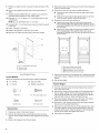
Reverse the door end caps as follows:
• Remove the screw and end cap from the top corner.
Move it diagonally to the opposite side's bottom corner,
keeping the straight side of the end cap facing the front of
the ice maker.
Remove the screw and end cap from the bottom corner.
Move it diagonally to the opposite side's top corner,
keeping the straight side of the end cap facing the front of
the ice maker.
A B
O
D C B A
A. Top Corner Open (no end cap)
B. Beginning Top Comer End Cap
C. Beginning Bottom Corner End Cap
D. Bottom Comer Open (no end cap)
7. Place the door back into the stainless skin, keeping the edge
protectors in place. Replace the two screws in the top and
bottom.
8. Set the door aside.
Reverse Hinges
1. Unscrew and remove the top hinge. Replace the screws in
the empty hinge holes.
2. Remove the screws from the bottom of the opposite side of
the ice maker cabinet. Turn the top hinge upside down so
that the hinge pin points up. Place the hinge on the bottom
opposite side of the ice maker and tighten screws.
3. Remove the plastic hinge pin sleeve from the "old" bottom
hinge and replace it on the new bottom hinge pin.
4. Remove the "old" bottom hinge screws and hinge. Replace
the screws in the empty hinge holes.
5. Remove the screws from the top of the opposite side of the
ice maker cabinet. Turn the hinge upside down so that the
hinge pin points down. Place the hinge on the top opposite
side of the ice maker and tighten the screws.
6. Remove the top hinge pin.

Replace Door
1. Place plastic hinge pin sleeve in the top hinge hole on the
door. Align the door with the top hinge hole and replace the
top hinge pin.
2. Replace the handle and handle screws (on some models).
Top Hinge
A. Hingepin C. Hinge
B. Hingepin sleeve
Bottom Hinge
.............. A
........ B
.........c
D. Hex-head hinge screw
J
A. Hex-head hinge screw C. Hinge
B. Hinge pin sleeve D. Hinge pin
Reverse Door Catch
1. Remove the hole plugs from the opposite side of the door
and set aside.
2. Remove the screws from the magnetic door catch and
replace it on the opposite side of the door.
0
3. Push the hole plugs into place on the opposite side of the
door.
Electrical Shock Hazard
Plug into a grounded 3 prong outlet.
Do not remove ground prong.
Do not use an adapter.
Do not use an extension cord,
Failure to follow these instructions can result in death,
fire, or electrical shock.
4. Plug in ice maker or reconnect power.
Your new ice maker may make sounds that are not familiar to
you. Because the sounds are new to you, you might be
concerned about them. Most of the new sounds are normal. Hard
surfaces such as floors, walls and cabinets can make the sounds
seem louder than they actually are. The following describes the
kinds of sounds that might be new to you and what may be
making them.
• You will hear a buzzing sound when the water valve opens to
fill the water reservoir for each cycle.
• Rattling noises may come from the flow of the refrigerant or
the water line. Items stored on top of the ice maker can also
make noises.
• The high-efficiency compressor may make a pulsating or high
pitched sound.
• Water running over the evaporator plate may make a
splashing sound.
• Water running from the evaporator plate to the water reservoir
may make a splashing sound.
• As each cycle ends, you may hear a gurgling sound due to
the refrigerant flowing in your ice maker.
• You may hear air being forced over the condenser by the
condenser fan.
• During the harvest cycle, you may hear a "thud" when the ice
sheet slides from the evaporator onto the cutter grid.
• When you first start the ice maker, you may hear water
running continuously. The ice maker is programmed to run a
rinse cycle before it begins to make ice.

ICEMAKERUSE
When you first start your ice maker, the water pan will fill and the
system will rinse itself before starting to make ice. The rinsing
process takes about 5 minutes.
Under normal operating conditions, the ice maker will cycle at
preset temperatures, The ice level sensor located in the ice
storage bin will monitor the ice levels.
IMPORTANT:
• If the water supply to the ice maker is turned off, be sure to
set the ice maker control to OFR
• The ice maker is designed to make clear ice from the majority
of water sources on a daily basis. If your results are
unsatisfactory, your water may need to be filtered or treated.
The Ice Making Process
1. Water is constantly circulated over a freezing plate. As the
water freezes into ice, the minerals in the water are rejected.
This produces a sheet of ice with a low mineral content.
2. When the desired thickness is reached, the ice sheet is
released and slides onto a cutter grid. The grid divides the
sheet into individual cubes.
3. The water containing the rejected minerals is drained after
each freezing cycle.
4. Fresh water enters the machine for the next ice making cycle.
5. Cubes fall into the storage bin. When the bin is full, the ice
maker shuts off automatically and restarts when more ice is
needed. The ice bin is not refrigerated, and some melting will
occur. The amount of melting varies with room temperature.
1. To start the normal ice making cycle, press ON.
2. To stop ice maker operation, press and hold OFR
On Control Clean
Off Lock Service Re s et
O-O-Q-O
NOTE:
• Pressing the ON/OFF switch does not shut off power to
the ice maker.
• Allow 24 hours to produce the first batch of ice. Discard
the first batch produced.
Control Lock
The control panel can be turned off for easy cleaning or to avoid
unintentional activation by children or small pets.
NOTE: The control lock feature does not shut off power to the ice
maker or to the ice maker bin light. It simply deactivates the
control panel.
1. To lock the control panel, press and hold the Control Lock
button until the indicator appears.
2. To unlock the control panel, press and hold the Control Lock
button until the indicator disappears.
Service
The service light indicates when service is needed. If the service
light turns on, turn the ice maker off and back on. If the service
light turns on again, call for service.
Clean/Reset
The Cleaning/Reset Status light will help you know when it is time
to clean your ice maker. The light will change to yellow. This tells
you it is almost time to clean your ice maker. It is recommended
that you clean the ice maker when the status light changes to red
OR ice production decreases significantly. To clean your ice
maker, see "Ice Maker System."
NOTE: As the room and water temperatures vary, so will the
amount of ice produced and stored. This means that higher
operating temperatures result in reduced ice production.
10

ICEMAKERCARE
The ice making system and the air cooled condenser need to be
cleaned regularly for the ice maker to operate at peak efficiency
and to avoid premature failure of system components. See the
"Ice Maker System" and the "Condenser" sections.
Exterior Surfaces
Wash the exterior enamel surfaces and gaskets with warm water
and mild soap or detergent. Wipe and dry. Regular use of a good
household appliance cleaner and wax will help protect the finish.
Do not use abrasive cleaners on enamel surfaces as they may
scratch the finish.
For products with a stainless steel exterior, use a clean sponge or
soft cloth and a mild detergent in warm water. Do not use
abrasive or harsh cleaners. Do not use chlorine bleach on the
stainless steel surfaces.
Ice Maker System
Minerals that are removed from water during the freezing cycle
will eventually form a hard scaly deposit in the water system.
Cleaning the system regularly helps remove the mineral scale
buildup. How often you need to clean the system depends upon
how hard your water is. With hard water of 15 to 20 grains/gal.
(4 to 5 grains/liter), you may need to clean the system as often as
every 6 months.
NOTE: Use one 16 oz (473 mL) bottle of approved ice maker
cleaner. To order, call f-800-JENNAIR and ask for Part Number
4396808. In Canada, call f-800-807-6777.
f. Press and hold the selector switch to OFR
2. Wait 5 to 10 minutes for the ice to fall into the storage bin.
Remove all ice from the storage bin.
3. Unscrew the drain cap from the bottom of the water pan
located inside the storage bin as shown. Allow the water to
drain completely.
4. Replace the drain cap securely on the water pan. Ifthe drain
cap is loose, water will empty from the water pan and you will
have either thin ice or no ice.
5. Read and follow all handling information on the cleaner bottle
before completing the steps below. Use one 16 oz (473 mL)
bottle of approved ice maker cleaner.
6. Pour one bottle of solution into the water pan. Fill the bottle
twice with tap water and pour it into the water pan.
B ...............
.......................... A
.......... o! ....................B
A. Water pan
B. Water pan thumb screws
C. Drain cap
7. Press and hold the CLEAN button. See "Using the Controls."
The light will blink, indicating that the cleaning cycle is in
process. When the indicator light turns green (approximately
70 minutes), the cleaning cycle is complete. During the
cleaning cycle, the system will both clean and rinse itself.
8. After the cleaning cycle is complete, remove the drain cap
from the water pan. Look for any cleaning solution left in the
water pan. If cleaning solution drains from the water pan, you
should run the clean cycle again. Be sure to replace the drain
cap securely on the water pan. Ifthe drain cap is loose, water
will empty from the water pan and you will have either thin ice
or no ice.
NOTE: Severe scale buildup may require repeated cleaning with
a fresh quantity of cleaning solution.
9. Push the selector switch to ON to resume ice production.
Condenser
A dirty or clogged condenser:
• Obstructs proper airflow.
• Reduces ice making capacity.
• Causes higher than recommended operating temperatures
which may lead to component failure.
Electrical Shock Hazard
Disconnect power before cleaning.
Replace all parts and panels before operating.
Failure to do so can result in death or electrical shock.
1. Unplug ice maker or disconnect power.
2. Remove the two screws in the lower access panel and the
two screws from the base grille area of the front panel
support. Pull forward to remove the lower access panel.
3. Pull the bottom forward and then pull down to remove the
lower access panel.
11

4= Remove dirt and lint from the condenser fins and the unit
compartment with a brush attachment on a vacuum cleaner.
5. Replace the lower access panel using the four screws.
6. Plug in ice maker or reconnect power.
Interior Components
1. Unplug ice maker or disconnect power.
2. Open the storage bin door and remove any ice that is in the
bin.
3. Remove the drain cap from the water pan and drain
thoroughly. Replace the drain cap securely on the water pan.
If the drain cap is loose, water will empty from the water pan,
and you will have either thin ice or no ice.
4. Remove the two screws that hold the cutter grid cover in
place and remove the cutter grid cover.
5. Unplug the wiring harness from the left side of the cutter grid.
A. Cutter grid cover
B. Screws
6. Unplug the ice level sensor from the right side of the cutter
grid. Pull the ice level sensor down and forward away from
the cutter grid.
7. Remove the right-hand and left-hand screws. Lift the cutter
grid up and out.
NOTE: Make sure the plastic spacer from the right-hand side
of the cutter grid bracket stays with the cutter grid.
A. Cutter grid harness D. Ice level sensor harness
B. Screw E. Plastic spacer
C. Cutter grid F, Screw
8=
9=
10.
Remove the two thumb screws that hold the water pan in
place. Push down with one hand on the front of the pan while
pulling forward on the bottom back side.
B'--
i
........ .........A
...........S
I _' _ ,. C
A.Water pan
B.Water pan thumb screws
C.Drain cap
Remove, clean and replace the ice scoop and ice scoop
holder.
• After removing the ice scoop, remove the holder by
removing the two thumb screws.
• Wash the ice scoop holder along with the other interior
components using the following instructions.
• Replace the ice scoop holder by replacing the thumb
screws.
A. Thumb screw
B. Ice scoop holder
Wash the interior components (cutter grid, exterior of hoses,
and water pan) and the storage bin, door gasket, ice scoop,
and ice scoop holder with mild soap or detergent and warm
water. Rinse in clean water. Then clean the same parts with a
solution of 1 tbs (15 mL) of household bleach in 1 gal. (3.8 L)
warm water. Rinse again thoroughly in clean water.
NOTE: Do not remove hoses. Do not wash plastic parts in
dishwasher. They cannot withstand temperatures above
145°F (63°0).
11. Replace water pan by pushing back on the bottom with one
hand while pushing up and back on the top. Secure the water
pan by replacing both screws.
12. Check the following:
• Drain cap from the water pan is securely in place. If the
drain cap is loose, water will empty from the water pan,
and you will have either thin ice or no ice.
• Hose from water pan is inserted into storage bin drain
opening.
13. Slide the cutter grid back into place and secure it by
replacing the right-hand screw and plastic spacer. Then
tighten the left-hand screw. Reconnect the cutter grid
harness and the ice level sensor harness.
14. Replace the cutter grid cover and the two screws.
15. Plug in ice maker or reconnect power.
12

'_i_C_O_¸_ _ _ '_ _ .... _C_ _ _ _ _ _t:_;t_
Electrical Shock Hazard
Disconnect power before servicing.
Replace all parts and panels before operating.
Failure to do so can result in death or electrical shock.
To shut down the ice maker:
1. Unplug ice maker or disconnect power.
2. Remove all ice from storage bin.
3. Shut off the water supply.
4. Remove the two screws in the lower access panel and the
two screws from the base grille area of the front panel
support. Pull forward to remove the lower access panel,
5. Disconnect the inlet and outlet lines to water valve. Allow
these lines to drain and then reconnect to the valve.
6. Replace lower access panel and screws.
7. Drain water from water pan by removing the drain cap.
8. If the room temperature will drop below 32°F (0°C), remove
water from the drain line.
For ice makers with a drain pump installed:
• Plug in ice maker or reconnect power.
• Turn ice maker off and remove all remaining ice from ice
bin.
• Pour 1 qt (0.95 L) of water into the ice bin near the drain
and let the unit stand for approximately 5 minutes. This
will allow the water in the bin to drain into the drain pump
so that the pump will remove the remaining water from
the ice bin and the drain pump.
• Unplug ice maker or disconnect power.
9. Before using again, clean the ice maker and storage bin.
f0. Plug into a grounded 3 prong outlet.
NOTE: All components of the ice maker are permanently
lubricated at the factory. They should not require any additional
oiling throughout the normal life of the machine.
TROUBLESHOOTING
Trythe solutions suggested here first in order to avoid the cost of an unnecessary service call.
Your ice maker will not operate
Electrical Shock Hazard
Plug into a grounded 3 prong outlet.
Do not remove ground prong.
Do not use an adapter.
Do not use an extension cord.
Failure to follow these instructions can result in death,
fire, or electrical shock.
Is the control set to ON? Be sure that the control is set to
ON,
Has a household fuse blown, or has a circuit breaker
tripped? Replace the fuse or reset the circuit breaker. If the
problem continues, call an electrician.
Is the room temperature cooler than normal? Room
temperature must be above 55°F (13°C). Otherwise, bin
thermostat may sense cold room temperature and shut off
even though the bin is not full of ice. Also, unit may not restart
once it does shut off.
Does the green light come on when the Clean button is
pushed? The ice maker is receiving power but may need
cleaning. See "Cleaning."
Does the ice maker have a drain pump? Ifthere was a large
amount of water added to the ice maker, wait a few minutes
for the drain pump to clear. If there is still water in the bin,
check to see whether the drain hose is kinked.
• Is the power cord plugged in? Plug into a grounded 3 prong
outlet.
13

Ice maker seems noisy
• Is water being circulated through the ice maker? This is
normal operation. Water is added once per ice-making cycle.
Is the water in the reservoir overflowing? This is normal.
This overflow helps to purge minerals that were removed from
the water during the ice making process.
• Is there a "whooshing" sound? Check the following things:
• Make sure that the water supply is hooked up and turned
On.
• Make sure that the drain cap is tight and the water drain
pan pump is securely attached to the water pan.
Is there ice between the evaporator plate and the cutting
grid? Check that the ice maker is level. See "Leveling." Ifthe
ice maker is level, and the problem persists, run a cleaning
cycle. See "Cleaning."
Is there scale buildup in the ice maker? If there is white
scale buildup in the ice maker's water or freezing system, you
should clean the ice maker. See "Interior Components" in the
"Cleaning" section.
• Is the drain cap securely in place? If the drain cap is loose,
water will empty from the water pan, and you will have either
thin ice or no ice. Tighten the drain cap if it is loose.
Grid isnot cutting ice sheets
Is the cutter grid securely in place? Check the cutter grid
harness plug to make sure the connection is intact. See
"Interior Components" section of "Cleaning" for instructions
on cutter grid removal.
Off taste, odor or gray color in the ice
Ice maker runs but produces no ice •
• Is the control set to ON? Be sure that the control is set to
ON. •
• Is the water supply connected? Make sure the water supply
is properly connected and turned on. •
• Is the drain cap securely in place? If the drain cap is loose,
water will empty from the water pan, and you will have either
thin ice or no ice. Tighten the drain cap.
• Is there debris in the drain tube? Clean the drain tube.
• Is there a kink in the drain line? Be sure that there are no
kinks in the line.
• Is the service light flashing on and off continually? Call for •
service.
Ice maker runs but produces very little ice
• Is the room temperature hotter than normal? Room
temperatures of more than 90°F (32°C) will normally reduce
ice production.
Electrical Shock Hazard
Disconnect power before servicing.
Replace all parts and panels before operating.
Failure to do so can result in death or electrical shock.
• Is the condenser dirty? Dirt or lint may be blocking the
airflow through the condenser. See "Condenser."
• Is there unusually high mineral content in the water
supply? The water may need to be filtered or treated.
Is there mineral scale buildup? Clean your ice maker. See
"Ice Maker System" in the "Cleaning" section.
Are there food items stored in the ice bin? Do not store any
foods in the ice bin.
Were all the packaging materials removed? Make sure that
all packaging materials were removed at the time of
installation.
Thin, soft or clumps of ice
• Is there unusually high mineral content in the water
supply? The water may need to be filtered or treated.
Is there mineral scale buildup? Clean your ice maker. See
"Ice Maker System" in the "Cleaning" section.
Are there clumps of ice in the bin? If ice is not used
regularly it will melt and form clumps. Break the clumps with
the ice scoop provided.
Excessive Weight Hazard
Use two or more people to move and install ice maker.
Failure to do so can result in back or other injury.
• Is the drain hose aligned over the drain? Move the ice
maker to align the drain. See "Water Supply Connection."
NOTE: Service technicians can not repair plumbing problems
outside of the ice maker. Call a licensed, qualified plumber.
14

ASSISTANCEORSERVICE
Before calling for assistance or service, please check
"Troubleshooting." It may save you the cost of a service call. If
you still need help, follow the instructions below.
When calling, please know the purchase date and the complete
model and serial number of your appliance. This information will
help us to better respond to your request.
If the problem is not due to one of the items listed in the
"Troubleshooting" section...
Call the dealer from whom your appliance was purchased, or call
Jenn-Air at 1-800-JENNAIR (1-800-536-6247} to locate an
authorized service company. When calling, please know the
purchase date and the complete model and serial number of your
appliance. Be sure to retain proof of purchase to verify warranty
status.
If the dealer or service company cannot resolve your problem,
write to:
Jenn-Air Brand Home Appliances
Customer eXperience Center
553 Benson Road
Benton Harbor, MI 49022-2692
Web address: www.jennair.com
Or call: 1-800-JENNAIR (1-800-536-6247).
U.S. customers using TTY for deaf, hearing impaired or speech
impaired, call: 1-800-688-2080 (Monday - Friday, 8:00 a.m. -
8:00 p.m. Eastern Time).
NOTE: When writing or calling about a service problem, please
include the following information:
1. Your name, address and daytime telephone number.
2. Appliance model number and serial number.
3. Name and address of your dealer or servicer.
4. A clear description of the problem you are having.
5. Proof of purchase (sales receipt).
User's guides, service manuals and parts information are
available from Jenn-Air Brand Home Appliances, Customer
eXperience Center.
If the problem is not due to one of the items listed in the
"Troubleshooting" section...
Call the dealer from whom your appliance was purchased, or call
Jenn-Air at 1-800-807-6777 to locate an authorized service
company. When calling, please know the purchase date and the
complete model and serial number of your appliance. Be sure to
retain proof of purchase to verify warranty status.
If the dealer or service company cannot resolve your problem,
write to:
Jenn-Air Brand Home Appliances
Customer Interaction Centre
1901 Minnesota Court
Mississauga, ON L5N 3A7
Web address: www.jennair.ca
Or call: 1-800-807-6777.
NOTE: When writing or calling about a service problem, please
include the following information:
1. Your name, address and daytime telephone number.
2. Appliance model number and serial number.
3. Name and address of your dealer or servicer.
4. A clear description of the problem you are having.
5. Proof of purchase (sales receipt).
User's guides, service manuals and parts information are
available from Jenn-Air Brand Home Appliances, Customer
Interaction Centre.
15

JENN-AIRTM ICE MAKERWARRANTY
ONE YEAR LIMITED WARRANTY
For one year from the date of purchase, when this major appliance is operated and maintained according to instructions attached to or
furnished with the product, Jenn-Air brand of Whirlpool Corporation or Whirlpool Canada LP (hereafter "Jenn-Air") will pay for factory
specified replacement parts and repair labor to correct defects in materials or workmanship. Service must be provided by a Jenn-Air
designated service company.
SECOND THROUGH FIFTH YEAR LIMITED WARRANTY ON SEALED REFRIGERATION SYSTEM PARTS
In second through fifth years from the date of purchase, when this product is operated in a residential setting, and is maintained
according to the instructions furnished with the product, Jenn-Air will pay for replacement parts and repair labor costs to correct
defects in materials or workmanship in the sealed refrigeration system. These parts are compressor, evaporator, condenser, dryer/
strainer, and connecting tubing. Service must be performed by a Jenn-Air designated service company.
ITEMS JENN-AIR WILL NOT PAY FOR
1. Service calls to correct the installation of your major appliance, to instruct you how to use your major appliance, to replace or repair
house fuses or to correct house wiring or plumbing.
2. Service calls to repair or replace appliance light bulbs, air filters or water filters. Those consumable parts are excluded from warranty
coverage.
3. Repairs when your major appliance is used for other than normal, single-family household use.
4. Damage resulting from accident, alteration, misuse, abuse, fire, flood, acts of God, improper installation, installation not in
accordance with electrical or plumbing codes, or use of products not approved by Jenn-Air.
5. Any food loss due to refrigerator or freezer product failures.
6. Replacement parts or repair labor costs for units operated outside the United States or Canada.
7. Pickup and delivery. This major appliance is designed to be repaired in the home.
8. Repairs to parts or systems resulting from unauthorized modifications made to the appliance.
9. Expenses for travel and transportation for product service in remote locations.
10. The removal and reinstallation of your appliance if it is installed in an inaccessible location or is not installed in accordance with
published installation instructions.
DISCLAIMER OF IMPLIED WARRANTIES; LIMITATION OF REMEDIES
CUSTOMER'S SOLE AND EXCLUSIVE REMEDY UNDER THIS LIMITED WARRANTY SHALL BE PRODUCT REPAIR AS PROVIDED
HEREIN. IMPLIED WARRANTIES, INCLUDING WARRANTIES OF MERCHANTABILITY OR FITNESS FOR A PARTICULAR PURPOSE,
ARE LIMITED TO ONE YEAR OR THE SHORTEST PERIOD ALLOWED BY LAW. JENNAIR SHALL NOT BE LIABLE FOR INCIDENTAL
OR CONSEQUENTIAL DAMAGES. SOME STATES AND PROVINCES DO NOT ALLOW THE EXCLUSION OR LIMITATION OF
INCIDENTAL OR CONSEQUENTIAL DAMAGES, OR LIMITATIONS ON THE DURATION OF IMPLIED WARRANTIES OF
MERCHANTABILITY OR FITNESS, SO THESE EXCLUSIONS OR LIMITATIONS MAY NOT APPLY TO YOU. THIS WARRANTY GIVES
YOU SPECIFIC LEGAL RIGHTS AND YOU MAY ALSO HAVE OTHER RIGHTS, WHICH VARY FROM STATETO STATE OR PROVINCE
TO PROVINCE.
Outside the 50 United States and Canada, this warranty does not apply. Contact your authorized Jenn-Air dealer to determine if another
warranty applies.
If you need service, first see the "Troubleshooting" section of the Use & Care Guide. After checking "Troubleshooting," additional help
can be found by checking the "Assistance or Service" section or by calling Jenn-Air. In the U.S.A., call 1-800-JENNAIR
(1-800-536-6247). In Canada, call 1-800-807-6777. 8/o7
Keep this book and your sales slip together for future
reference. You must provide proof of purchase or installation
date for in-warranty service.
Write down the following information about your major appliance
to better help you obtain assistance or service if you ever need it.
You will need to know your complete model number and serial
number. You can find this information on the model and serial
number label located on the product.
Dealer name
Address
Phone number
Model number
Serial number
Purchase date
16

SEGURIDADDELAFABRICADEHIELO
Su seguridad y la seguridad de los demas es muy importante.
Hemos incluido muchos mensajes importantes de seguridad en este manual yen su electrodomestico. Lea y obedezca siempre
todos los mensajes de seguridad.
Este es el simbolo de advertencia de seguridad.
Este sfmbolo le llama la atenci6n sobre peligros potenciales que pueden ocasionar la muerte o una lesi6n a
usted y a los demas.
Todos los mensajes de seguridad iran a continuaci6n del simbolo de advertencia de seguridad y de la palabra
"PELIGRO" o "ADVERTENCIA". Estas palabras significan:
Si no sigue las instrucciones de inmediato, usted puede
morir o sufrir una lesibn grave.
Si no sigue las instrucciones, usted puede morir o sufrir
una lesi6n grave.
Todos los mensajes de seguridad le diran el peligro potencial, le diran c6mo reducir las posibilidades de sufrir una lesi6n y Io que
puede suceder si no se siguen las instrucciones.
INSTRUCCIONES IMPORTANTES DE SEGURIDAD
ADVERTENCIA: Para reducir el riesgo de incendio, choque el6ctrico o lesiones personaies al usar
Ja f&brica de hieJo, siga estas precauciones b&sicas:
• Conecte a un contacto de pared de conexi6n a tierra de
3 terminales.
• No quite el terminal de conexi6n a tierra.
• No use un adaptador.
• No use un cable electrico de extension.
• Desconecte el suministro de energ[a antes de limpiarlo.
[] Desconecte el suministro de energia antes de darle
servicio.
[] Vuelva a colocar todos los componentes y paneles
antes de hacerlo funcionar.
[] Use dos o mas personas para mover e instalar la
fabrica de hielo.
GUARDE ESTAS INSTRUCCIONES
INSTRUCCIONESDEINSTALACION
HERRAMIENTAS NECESARIAS:
ReL_nalas herramientas y piezas requeridas antes de comenzar la
instalaci6n.
Lea y siga las instrucciones provistas con cualquiera de las
herramientas enlistadas aqui.
• Taladro inalambrico • Lapiz
• Destornillador Phillips • Cinta adhesiva
• Router o cepillo • Cinta de medir
mecanico
• Toalla o pedazo de cart6n
PIEZAS NECESARIAS:
Panel de la puerta de revestimiento hecho a la medida - Vea
"lnstrucciones de instalaci6n del panel hecho a la medida,"
tornillos para madera de cabeza de cono achatado #8 x 1/2"(8)
PIEZAS SUMINISTRADAS:
• Almohadillas adhesivas (4)
Si usted planea instalar un panel de revestimiento a la medida,
usted mismo necesitara crear el panel o consultar a un ebanista
o earpintero califieado.
IMP@RTANTE:
• El espesor del panel de revestimiento debe ser 3/4"
(1,91 cm).
• El panel de revestimiento no debe pesar mas de 8 Ibs
(3,62 kg).
• Los panels de revestimiento que pesan mas de Io
recomendado pueden causar dar_o a su fabrica de hielo.
• Haga coincidir la direcci6n de las vetas de la madera con
la de los muebles adyacentes.
• Lije los bordes del panel para proporcionar un terminado
liso.
• Use sellador de humedad a ambos lados y todos los
bordes del panel para proporcionar protecci6n contra la
humedad.
17

Cree el panel de revestimiento hecho a la medida usando las
dimensiones mostradas.
NOTA: El panel debe ser preparado como se muestra para
permitir los espacios adecuados para la puerta.
2931/e4''
(74,9 cm)
1433/64"
(36,9 crn)
11/4" 11/4"
(3,19 cm) (3,18 cm)
(6,86o1:;il, (1,01oo,
1/4"
(6,35 mm)
eo
Limpieza antes del uso
Luego de quitar todos los materiales de empaque, limpie el
interior de su fabrica de hielo antes de usarla. Consulte las
instrucciones de limpieza en la secci6n "Cuidado de su fabrica
de hielo".
...........+.,,, ..................,, U_/} _,,..C/_,,.O
Para asegurar la ventilaci6n adecuada de su fabrica de hielo,
la parte del frente debe mantenerse completamente libre de
obstrucciones. La parte superior y los tres lades de la unidad
pueden estar cerrados, pero la instalaci6n debe ser hecha de
manera que la fabrica de hielo pueda ser movida hacia
adelante para hacede el servicio, si fuera necesario.
La instalaci6n de la fabrica de hielo requiere una entrada de
suministro de agua con tuber(a de cobre blando de 1/4"
(6,35 mm) de diametro exterior y una valvula de cierre, asi
come tambien un sistema de desagQe per gravedad o una
bomba condensadora para Ilevar el agua a un desagQe ya
existente.
Elija un Area bien ventilada con temperaturas por encima de
los 55°F (13°C) y por debajo de los 110°F (43°C). Los mejores
resultados se Iogran con temperaturas que oscilan entre 70°F
(21°C) y 90°F (32°C).
Esta unidad debe set instalada en un Area protegida de las
inclemencias del tiempo, tales como el viento, Iluvia, roc(o de
agua o goteras.
Cuando instale la fabrica de hielo debajo de un mostrador,
siga las dimensiones de abertura recomendadas que se
ilustran a continuaci6n. Coloque accesorios electricos o de
plomer(a en la zona recomendada come se indica.
NOTA:
• AsegQrese de que el cable de alimentaci6n electrica no
este prensado entre la fabrica de hielo y el armario.
• AsegQrese de que la linea de suministro de agua no este
prensada entre la fabrica de hielo y el armario.
• AsegQrese de que la linea de desagQe (en algunos
modelos) no este prensada entre la fabrica de hielo y el
armario.
Peligro de Peso Excesivo
Use dos o mas personas para mover e instalar
la fabrica de hielo.
No seguir esta instruccion puede ocasionar una
lesion en la espalda u otro tipo de lesiones.
Cbmo quitar los materiales de empaque
Quite las cintas y la goma de su fabrica de hielo antes de usarla.
• Para eliminar los residuos de cinta o goma, frote el Area
energicamente con su dedo pulgar. Los residuos de la cinta
adhesiva o goma tambien pueden quitarse frotando un poco
de detergente I(quido para vajillas con los dedos. Limpie con
agua tibia y seque.
No use instrumentos filosos, alcohol para fricciones, liquidos
inflamables, o productos de limpieza abrasivos para eliminar
los restos de cinta o goma. No use blanqueador con cloro en
las superficies de acero inoxidable de la fabrica de hielo.
Estos productos pueden daSar la superficie de su fabrica de
hielo.
34"
(86,4 cm)
Min.
341/2"
(87,6 cm)
Max.
I)-
281/2"
(72,4 cm)
_-'_ 15" -_
(39,1 cm)
A. Ubicacidn recomendada para accesorios el_ctricos y de
plomerfa.
B. Nivel del piso
18

Usted debera elegir una ubicaci6n donde el piso este
nivelado. Es importante que la fabrica de hielo este nivelada
para su funcionamiento adecuado. De ser necesario, usted
puede regular la altura de la fabrica de hielo cambiando la
altura de las patas niveladoras. Consulte la secci6n
"Nivelaci6n".
Peligro de Choque Electrico
Conecte a un contacto de pared de cone×ion a tierra de
3 terminaJes.
No quite la terminal de cone×ion a tierra.
No use un adaptador.
No use un cable electrico de exteneiono
No eeguir eetae instrucciones puede ocasionar
la muerte, incendio o choque electrico.
Antes de trasladar la fabrica de hielo a su ubicaci6n final, es
importante cerciorarse de que tenga la conexi6n electrica
apropiada:
Se requiere un circuito de suministro electrico con fusibles de 15
6 20 Amp., de 115 V, 60 Hz, de CA solamente, conectado
adecuadamente a tierra de acuerdo con el C6digo Nacional de
Electricidad y con las normas y c6digos locales.
Se recomienda tener un circuito separado que sirva s61o para la
fabrica de hielo. Use un receptaculo que no pueda ser
desconectado con un interruptor o con una cadenilla de tiro.
IMPORTANTE: Si este producto esta conectado a un
tomacorriente protegido por un interruptor del circuito de falla
electrica de puesta a tierra (GFCI - Ground Fault Circuit
Interrupter), puede ocurrir un disparo brusco del suministro de
corriente, Io que resultara en una perdida de refrigeraci6n. Esto
puede afectar la calidad y el sabor del hielo. Si ha ocurrido un
disparo brusco, y el hielo aparenta estar en malas condiciones,
deshagase del mismo.
M_todo recomendado para la conexibn a tierra
Para su seguridad personal este electrodomestico debe ser
conectado a tierra. Este electrodomestico esta equipado con un
cable electrico provisto de un enchufe de tres terminales
conectado a tierra. Para reducir el peligro de posibles choques
electricos, el cable debe ser enchufado en un contacto
apropiado de pared de tres terminales, conectado a tierra de
acuerdo con el C6digo Nacional de Electricidad y con los
c6digos y normas locales. Si no hubiera un contacto de pared
adecuado, el cliente tiene la responsabilidad de contratar a un
electricista calificado para instalar un contacto de pared
apropiado de tres terminales con conexi6n a tierra.
Se necesita un suministro de agua fria con presi6n de agua entre
30 y 120 Ibs/pulg 2(207 a 827 kPa) para hacer funcionar la fabrica
de hielo. Si usted tiene preguntas acerca de la presi6n de agua,
Ilame a un plomero competente autorizado.
Suministro de agua de 6smosis inversa
IMPORTANTE: La presi6n del suministro de agua que sale de un
sistema de 6smosis inversa y va a la valvula de entrada de agua
de la fabrica de hielo necesitara set entre 30 y 120 Ibs/pulg _
(207 a 827 kPa).
Si se conecta un sistema de filtraci6n de agua de 6smosis
inversa al suministro de agua fria, la presi6n de agua al sistema
de 6smosis inversa necesitara ser de un minimo de 40 a
60 Ibs/pulg _(276 a 414 kPa). El sistema de 6smosis inversa debe
suministrar 1 gal6n (3,79 L) de agua por hora a la fabrica de hielo
para que esta funcione adecuadamente.
Si la presi6n del agua del sistema de 6smosis inversa es menor
de 40 a 60 Ibs/pulg _(276 a 414 kPa):
• Verifique si el filtro de sedimentos en el sistema de 6smosis
inversa esta bloqueado y reemplacelo si fuera necesario.
• Deje que se vuelva a Ilenar el tanque de almacenaje del
sistema de 6smosis inversa despues del uso intenso.
Si tiene preguntas acerca de la presi6n del agua, Ilame a un
plomero competente autorizado.
Es importante que la fabrica de hielo este nivelada para que
funcione adecuadamente. Dependiendo del lugar donde instale
la fabrica de hielo, puede necesitar hacer varios ajustes para
nivelarla. Tambien puede usar las patas niveladoras para reducir
la altura de la fabrica de hielo para las instalaciones debajo de
mostradores.
Herramientas necesarias:
Re_na las herramientas y piezas necesarias antes de comenzar
la instalaci6n.
• Nivel de 9"
• Llave detuercas ajustable
NOTA: Es mas facil ajustar las patas niveladoras si tiene otra
persona para ayudarlo.
1. Mueva la fabrica de hielo a su ubicaci6n final.
NOTA: Siesta es una instalaci6n empotrada, mueva la
fabrica de hielo tan cerca de su ubicaci6n final como sea
posible.
2. Coloque un nivel de carpintero en la parte superior del
producto para ver si la fabrica de hielo esta nivelada desde
adelante hacia atras y de lado a lado.
3. Empuje hacia arriba en la parte superior frontal de la fabrica
de hielo y luego Iocalice los tornillos niveladores que se
encuentran en la parte inferior frontal de la fabrica de hielo.
19

4.
Usando una Ilave de tuercas ajustable, cambie la altura de las
patas de la siguiente manera:
• Gire la pata niveladora hacia la derecha para bajar ese
lado de la fabrica de hielo,
• Gire la pata niveladora hacia la izquierda para levantar
ese lado de la fabrica de hielo.
NOTA: La fabrica de hielo no debe oscilar. Use calzas para
agregarle estabilidad cuando sea necesario.
5. Empuje hacia arriba en la parte superior trasera de la fabrica
de hielo y Iocalice las patas niveladoras que se encuentran el
la parte inferior trasera de la fabrica de hielo.
6. Siga las instrucciones del paso 4 para cambiar la altura de las
patas.
7. Use un nivel de carpintero para volver a verificar la fabrica de
hielo para ver siesta nivelada desde adelante hacia atras y
de lado a lade, Si la fabrica de hielo no esta nivelada, repita
los pasos del 2 al 5, Si la fabrica de hielo esta nivelada,
proceda a la secci6n "Conexi6n del suministro de agua".
Lea todas las instrueeiones cuidadosamente antes de
comenzar.
IMPORTANTE:
• Todas las instalaciones de plomerfa deben efectuarse de
conformidad con el C6digo de Plomeria Internacional y los
c6digos y ordenanzas de plomerfa locales,
• Use tuberia de cobre y revise si hay fugas,
• Instale la tuberia de cobre s61o en Areas donde las
temperaturas permanezcan encima del punto de
congelaci6n,
Herramientas necesarias:
Re0na las herramientas y piezas necesarias antes de comenzar
la instalaci6n, Lea y siga las instrucciones provistas con
cualquiera de las herramientas enlistadas aqui,
• Destornillador de hoja plana
• Llaves de extremo abierto de 7/16"y 1/2"0 dos Ilaves de
tuercas ajustables
• Llave para tuercas de 1/4"
• Broca de 1/4"
• Taladro inalambrico
NOTA: El distribuidor de su fabrica de hielo tiene un juego
disponible que consta de una valvula de cierre del tipo montura
de 1/4"(6,35 ram), una uni6n y tuberia de cobre. Antes de
comprar, asegQrese de que la valvula del tipo montura cumple
con los c6digos de plomeria locales. No use valvulas del tipo
perforado o de montura de s/16"(4,76 ram), las cuales reducen el
flujo de agua y se obstruyen con mayor facilidad,
Conexibn de la tuberia de agua
2.
3.
4.
5.
Cierre el suministro principal del agua, Abra el grifo mas
cercano el tiempo suficiente para limpiar la tuberia del agua,
Localice un tube de agua fria vertical de 1/2"(12,70 mm) a 11/4"
(3,18 cm) cerca de la fabrica de hielo.
NOTA: Un tubo horizontal tambien funcionara pero se debera
seguir el siguiente procedimiento: perfore en el lado superior
del tubo, no en la parte inferior. Esto ayudara a mantener el
agua lejos de la perforaci6n, Tambien evita que el sedimento
normal se acumule en la valvula.
Usando un taladro inalambrico, perfore un agujero de 1/4"
(6,35 mm) en el tube de agua fria que usted ha seleccionado.
Sujete la valvula de cierre al tubo de agua frfa empleando la
abrazadera para tuberfa. AsegQrese de que el extremo de
salida este bien encajado en el agujero perforado de
1/4"(6,35 mm) en el tubo de agua y que la arandela este
debajo de la abrazadera del tubo. Ajuste la tuerca de presi6n.
Ajuste los tornillos de la abrazadera del tubo con cuidado y
de manera uniforme de modo que la arandela sirva de sello
hermetico al agua. No ajuste demasiado la abrazadera del
tubo, o de Io contrario podria aplastar el tubo de agua fria si
se trata de tuberia de cobre blando. No use valvulas del tipo
perforado o de montura de 3/ld' (4,76 mm), las cuales reducen
el flujo de agua y se obstruyen con mayor facilidad.
Ahora esta listo para conectar la tuberfa de cobre. Use una
tuberia de cobre blando de 1/4"(6,35 mm) de diametro
exterior para el suministro de agua fria.
• AsegQrese de tener la Iongitud adecuada necesaria para
el trabajo. Cerci6rese de que ambos extremos de la
tuberia de cobre esten cortados en angulo recto,
• Deslice el manguito de compresi6n y la tuerca de
compresi6n en la tuberia de cobre segQn se ilustra.
Introduzca el extremo de la tuberia en el extremo de
salida en angulo recto hasta donde sea posible. Atornille
la tuerca de compresi6n con el extremo de salida usando
la Ilave de tuercas ajustable. No ajuste demasiado,
....... A
H, '_' B
_" .........C
G__-"_,,, D
A. Tubo de agua frfa
B.Abrazadera para tuberfa
C. Tuberfa de cobre
D. Acoplamiento
(comprado)
E. Tuerca de compresidn
F. Manguito de
compresidn
G. V#lvula de cierre
H. Tuerca de presidn
6.
Coloque el extremo libre de la tuberia en un recipiente o un
fregadero y abra el suministro principal del agua y deje correr
el agua por la tuberfa hasta que el agua salga limpia. Cierre la
valvula de cierre del tube de agua,
NOTA: Siempre desagQe la tuber[a de agua antes de efectuar
la conexi6n final al orificio de entrada de la valvula de agua
para evitar un probable mal funcionamiento de la valvula de
agua.
2O
La page est en cours de chargement...
La page est en cours de chargement...
La page est en cours de chargement...
La page est en cours de chargement...
La page est en cours de chargement...
La page est en cours de chargement...
La page est en cours de chargement...
La page est en cours de chargement...
La page est en cours de chargement...
La page est en cours de chargement...
La page est en cours de chargement...
La page est en cours de chargement...
La page est en cours de chargement...
La page est en cours de chargement...
La page est en cours de chargement...
La page est en cours de chargement...
La page est en cours de chargement...
La page est en cours de chargement...
La page est en cours de chargement...
La page est en cours de chargement...
La page est en cours de chargement...
La page est en cours de chargement...
La page est en cours de chargement...
La page est en cours de chargement...
La page est en cours de chargement...
La page est en cours de chargement...
La page est en cours de chargement...
La page est en cours de chargement...
-
 1
1
-
 2
2
-
 3
3
-
 4
4
-
 5
5
-
 6
6
-
 7
7
-
 8
8
-
 9
9
-
 10
10
-
 11
11
-
 12
12
-
 13
13
-
 14
14
-
 15
15
-
 16
16
-
 17
17
-
 18
18
-
 19
19
-
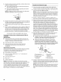 20
20
-
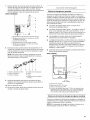 21
21
-
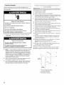 22
22
-
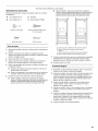 23
23
-
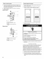 24
24
-
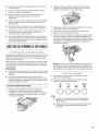 25
25
-
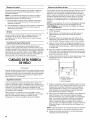 26
26
-
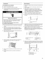 27
27
-
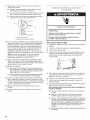 28
28
-
 29
29
-
 30
30
-
 31
31
-
 32
32
-
 33
33
-
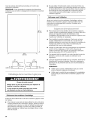 34
34
-
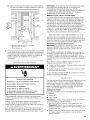 35
35
-
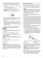 36
36
-
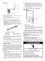 37
37
-
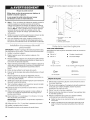 38
38
-
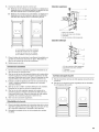 39
39
-
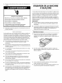 40
40
-
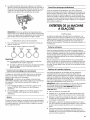 41
41
-
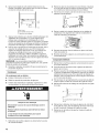 42
42
-
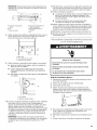 43
43
-
 44
44
-
 45
45
-
 46
46
-
 47
47
-
 48
48


Jenn-Air JIM158XBCX2 Le manuel du propriétaire
- Taper
- Le manuel du propriétaire
- Ce manuel convient également à
dans d''autres langues
Documents connexes
-
Jenn-Air JIM158BCX3 Le manuel du propriétaire
-
Jenn-Air JIM158XYCX0 Le manuel du propriétaire
-
-
-
-
-
-
Jenn-Air JUIFN15HX Le manuel du propriétaire