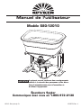
SPYKER S80-12010 Le manuel du propriétaire
- Catégorie
- Tondeuses à gazon
- Taper
- Le manuel du propriétaire

1008754 Rev. A©2012 Brinly-Hardy Co.
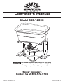
Spyker Spreaders
Contact Us at 800.972.6130
This manual contains information for the safety
of persons and property. Read it carefully before
assembly and operation of the equipment!
IMPORTANT
Model S80-12010
Operator's Manual

1008754 Rev. A 2
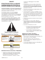
SAFETY
SAFETY LABELS
UNDERSTANDING THE MACHINE SAFETY
LABELS:
The machine safety labels shown in this section are
placed in important areas on your machine to draw
attention to potential safety hazards.
On your machine safety labels, the words DANGER,
WARNING, and CAUTION are used with this safety-alert
symbol. DANGER identifi es the most serious hazards.
The operator's manual also explains any potential safety
hazards whenever necessary in special safety messages
that are identifi ed with the word CAUTION and the safety-
alert symbol.
Safety Alert Symbol
Safety Labels on Spreader
5HDGVSUHDGHU2SHUDWRU¶V0DQXDO
$OORZIRUORQJHUEUDNLQJGLVWDQFHV
9HKLFOHVSHHGVKRXOGEHOHVVWKDQPSK6SHHG
VKRXOGDOZD\VEHVORZHQRXJKWRPDLQWDLQFRQWURO,I
\RXUYHKLFOHPDQXDOVSHFLILHVDVSHHGVORZHUWKDQ
PSKZKHQFDUU\LQJORDGVWKHQGRQRWH[FHHGWKH
VSHFLILHGVSHHG
'RQRWGULYHRQVORSHVJUHDWHUWKDQGHJUHHV
(PSW\VSUHDGHUKRSSHUDQGWUDYHOVORZO\ZKLOHJRLQJXS
DQGGRZQWUDLOHUUDPSV
WARNING
TO PREVENT LOSS OF CONTROL WHILE
SPREADER IS ATTACHED TO VEHICLE:
/LVH]OHPDQXHOGHO¶RSpUDWHXUGHO¶pSDQGHXU
3UpYR\H]GHSOXVORQJXHVGLVWDQFHVGHIUHLQDJH
/DYLWHVVHGXYpKLFXOHGRLWrWUHLQIpULHXUHjNPK
PLK/DYLWHVVHGRLWWRXMRXUVrWUHDVVH]OHQWH
SRXUSHUPHWWUHGHFRQVHUYHUODPDvWULVHGXYpKLFXOH
6LOHPDQXHOGHYRWUHYpKLFXOHLQGLTXHXQHYLWHVVH
LQIpULHXUHjNPKPLKORUVGXWUDQVSRUWGH
FKDUJHVQHGpSDVVH]SDVODYLWHVVHLQGLTXpH
1HFRQGXLVH]SDVOHYpKLFXOHVXUXQHLQFOLQDLVRQ
VXSpULHXUHjGHJUpV
9LGH]ODWUpPLHGHO¶pSDQGHXUHWGpSODFH]YRXV
OHQWHPHQWORUVTXHYRXVPRQWH]HWGHVFHQGH]OD
UDPSHG¶XQHUHPRUTXH
POUR ÉVITER TOUTE PERTE DE CONTRÔLE
LORSQUE L’ÉPANDEUR EST FIXÉ AU VÉHICULE :
AVERTISSEMENT
1008753
1HYHUSODFHKDQGVLQWRKRSSHURUDGMXVW$FFXZD\
'LUHFWLRQDO&RQWUROZKLOHPRWRULVUXQQLQJ
,IXVLQJKDQGWRRSHQRUFORVHJDWHDFWXDWRUXVH
H[WHQVLRQ
CAUTION
TO PREVENT INJURY TO HAND:
1HSODFH]SDVYRVPDLQVGDQVODWUpPLHHWQ¶DMXVWH]
SDVOHFRQWU{OHGHGLUHFWLRQGHODPDFKLQH$FFXZD\
ORUVTXHOHPRWHXUHVWHQPDUFKH
8WLOLVH]ODUDOORQJHVLYRXVRXYUH]RXIHUPH]ODSRUWH
GXGLVSRVLWLIGHFRPPDQGHDYHFYRWUHPDLQ
MISE EN GARDE
POUR ÉVITER LES BLESSURES AUX MAINS :
1008785
1008785
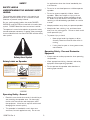
Operating Safely - General
• Read this manual and the manual of the vehicle you
are attaching the spreader onto. Be thoroughly
familiar with the controls and the proper use of
the equipment. Know how to stop the vehicle and
disengage the controls quickly.
• This spreader is intended for use in lawn care
and snow/ice melt applications only. Do not use
for applications other than those intended by the
manufacturer.
• Do not let an untrained person or children operate
spreader.
• Do not let anyone, especially children, ride on
spreader. Riders are subject to injury such as
being struck by foreign objects and being thrown
off. Riders may also obstruct the operator's view,
resulting in the vehicle being operated in an unsafe
manner.
• Keep bystanders away when you operate spreader.
• Keep hands, feet, clothing, hair, and loose items
away from any moving parts. Failure to check could
cause personal injury.
• To prevent injury to hand:
• Never place hands into hopper or adjust
Accuway Directional Control while motor is
running.
• If using hand to open or close gate actuator,
use extension.
Operating Safely - Personal Protective
Equipment
• Always wear ear and eye protection when operating
the spreader.
• Wear appropriate clothing, footwear, and safety
equipment when operating spreader.
• Do not operate the spreader when barefoot or
wearing open sandals.

1008754 Rev. A3
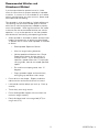
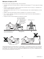
Recommended Vehicles and
Attachment Method
If you have purchased an optional mount kit, follow
mount kit instructions for proper assembly of spreader
to vehicle. If a mount kit is not available for your vehicle,
and you are fabricating your own mount kit, please read
and understand the following.
This spreader is to be attached to 4 wheel vehicles only.
The following are the recommended types of vehicles
and minimum vehicle requirements needed to properly
mount the spreader. While signifi cant effort was made
to ensure that the recommended vehicles are safe for
operation, it is up to the operator to use the spreader
and vehicle with the following safe operating practices.
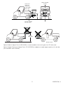
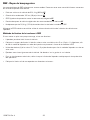
• When spreader is attached to vehicle, be aware that
handling characteristics of vehicle may be affected.
To prevent loss of control when spreader is attached
to vehicle.
• Read spreader Operators Manual.
• Allow for longer braking distances.
• Vehicle speed should be less than 10mph.
Speed should always be slow enough to
maintain control. If your vehicle manual
specifi es a speed slower than 10 mph when
carrying loads, then do not exceed specifi ed
speed.
• Do not drive on slopes greater than 10
degrees.
• Empty spreader hopper and travel slowly
while going up and down trailer ramps.
• Do not drive on wet slopes. Slippery conditions
reduce traction and could cause loss of control.
• Look behind machine before you back up. Back up
carefully.
• Travel slowly over rough terrain.
• Do not load spreader hopper with more than the
maximum weight capacity.
• Evenly distribute loads in the cargo bed (UTV) or
cargo rack (ATV).

1008754 Rev. A 4
UTV - Utility Terrain Vehicle
The following UTV specifi cations are recommended. Review your Vehicle Operators Manual for your vehicle
specifi cations.
• Minimum vehicle dry weight of 1050 lb AND
• Minimum wheelbase of 70.9" AND
• Minimum payload capacity of 800lb AND
• Vehicle tire pressure is at manufacturer's recommended settings AND
• The Gross Vehicle Weight (GVW) must never exceed the Gross Vehicle Weight Rating (GVWR) of machine.
Failure to do so may limit a machines handling characteristics. To calculate GVW, add the following:
(A) Empty Vehicle Weight (Full fl uids. See vehicle operators manual)
(B) Occupant Weight (driver + passenger if applicable)
(C) Cargo Box Load Weight (Do not exceed maximum cargo box capacity)
(D) Optional Vehicle Accessories Weight (cab, snow blade, etc)
(E) Spreader Weight (See Capacities section)
(F) Weight of Material in Hopper (do not exceed Hopper Capacity. See Capacity Section)
(G) Weight of Spreader Mount
GVW = A+B+C+D+E+F+G
GVW must be lower than GVWR (see Vehicle Operators Manual for rating). If not, do not operate vehicle and
reduce weight until GVW is lower than GVWR.
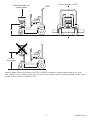
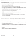
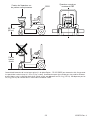
How to Attach to UTV's
If you are developing your own mount, follow these guidelines:
• Spreader should be mounted to rear of vehicle, using UTV receiver hitch as the main support.
• Fabricate a mount bracket using a minimum of 2" x 11 gage square steel tubing that attaches spreader frame
to UTV hitch.
• Use at least (4) 1/2" diameter bolts to mount spreader frame to square steel tubing.
• Center spreader with Center Line of Vehicle. Do not offset to the Left or Right.
• For additional support, use ratchet style tie straps to secure spreader frame to UTV bed.
• Fabricate mount to accommodate the following dimensions:

1008754 Rev. A5
No front mount
Do not
mount high
22”
Locate and
tighten tie
straps from
frame to bed
(both sides)
Use UTV receiver
hitch for mount.
Center spreader
on UTV
5.5”
Optional Cable Kit (Spyker Part #: KSP14-CAB1) is recommended to control rate gate from UTV driver seat.
Optional Hopper Extension Kit (Spyker Part #: 05-120-3600) is needed to increase hopper capacity to 4 cubic feet
(not to exceed a total of 220lbs).

1008754 Rev. A 6
ATV - All Terrain Vehicle
The following ATV specifi cations are recommended. Review your Vehicle Operators Manual for your vehicle
specifi cations.
• Minimum vehicle dry weight of 615 lb AND
• Minimum wheelbase of 48.4" AND
• Minimum rear rack capacity of 176 lb AND
• Vehicle tire pressure is at manufacturer's recommended settings AND
• Do not exceed 120lb of material in hopper on ATV's AND
• Do not exceed maximum weight capacity of vehicle. To calculate, add the following:
(A) Driver Weight
(B) Rear Cargo Weight
(C) Front Cargo Weight
(D) Accessories Weight (snow blade, etc)
(E) Spreader Weight (See Capacities section)
(F) Weight of Material in Hopper (Do not exceed 120 lb.)
(G) Weight of Spreader Mount
Weight Capacity = A+B+C+D+E+F+G
Weight Capacity must be lower than maximum weight capacity (See Vehicle Operators Manual). If not, do not
operate vehicle and reduce weight until Weight Capacity is lower than maximum weight capacity.
• Do not exceed rear rack weight capacity
Rear Weight = B+E+F+G
Rear Weight must be lower than the rear rack capacity weight (See Vehicle Operators Manual). If not, do not
operate vehicle and reduce weight until Rear Weight is lower than rear rack weight capacity.

1008754 Rev. A7
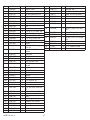
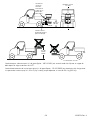
How to Attach to ATV's
If you are developing your own mount, follow these guidelines:
• Spreader should be mounted to rear of vehicle, using ATV receiver hitch as main mount support.
• Fabricate a mount bracket using a minimum of 2" x 11 gage square steel tubing that attaches spreader frame
to ATV hitch.
• Use at least (4) 1/2" diameter bolts to mount spreader frame to square steel tubing.
• Center spreader with Center Line of Vehicle. Do not offset to the Left or Right.
• For additional support, use ratchet style tie straps to secure spreader frame to ATV Rear Cargo Rack.
• Fabricate mount to accommodate the following dimensions:
Mount to ATV
receiver hitch
Mount as close to ATV as
possible while allowing
linkages to work
Locate and tighten
tie strap from
frame to rear cargo
rack (both sides)
Handle extension
may be necessary
22”
Center spreader on
ATV
No front mount
Do not
mount high
Optional Hopper Extension Kit (Spyker Part #: 05-120-3600) is needed to increase hopper capacity to 4 cubic
feet. Extension may be used for lighter, fl uffy material, but total hopper capacity should not exceed 120 lbs. Do not
exceed 120lb of material in hopper on ATV's.

1008754 Rev. A 8
ZTR - Zero Turn Radius
The following ZTR specifi cations are recommended. Review your Vehicle Operators Manual for your vehicle
specifi cations.
• Minimum vehicle dry weight of 863 lbs AND
• Minimum 48" mower deck AND
• Must have ROPS (Rollover Protection System) AND
• Vehicle tire pressure is at manufacturer's recommended settings AND
• Do not exceed 120lb of material in hopper on ZTR's.
Keep the ROPS in the raised and locked position and use the seat belt when operating the vehicle with spreader.
How to Attach to ZTR's
If you are developing your own mount, follow these guidelines:
• Spreader can be mounted to front of vehicle
• Fabricate a mount bracket using a minimum of 2" x 11 gage square steel tubing that attaches spreader frame
to front ZTR caster wheel frame.
• Use at least (4) 1/2" diameter bolts to mount spreader frame to square steel tubing.
• Center spreader with Center Line of Vehicle. Do not offset to the Left or Right.
• Do not mount spreader so that it blocks operators fi eld of vision for safe operation.
• Fabricate mount to accommodate the following dimensions:

1008754 Rev. A9
Mount spreader over
caster wheels ROPS
22”
Center spreader on ZTR
Do not
mount high
Optional Hopper Extension Kit (Spyker Part #:05-120-3600) is needed to increase hopper capacity to 4 cubic
feet. Extension may be used for lighter, fl uffy material, but total hopper capacity should not exceed 120 lbs. Do not
exceed 120lb of material in hopper on ZTR's.

1008754 Rev. A 10
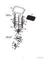
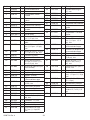
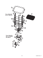
Item Part Number Qty Description
1 1006262 1 Hopper Cover
2 1008720 1 Screen
3 1008734 1 Variable Speed Control
4 1000203 1 Hopper Bottom Bearing
5 1000211 1 Dial Mount
6 1000215 1 Pine Tree Clip
7 1000725-01 1 Rate Gate Link
8 1000733 1 Dial
9 1000766-01 1 Mulch Bottom
10 1001264 6 #10-32 x 1/2" Bolt, SS
11 1001521 4 Rate Gate Guide
12 1004880 6 1/4" x 1/2" Bolt, SS
13 1006084 2 1/4" x 3/4" Bolt, SS
14 1006147 1 Accuway Diffuser
15 1007329 1 T-Knob
16 1007386 5 1/4" x 3/4" Carriage
Bolt, SS
17 1007889 6 Nylon Cable Tie (Not
Shown)
18 1008244 1 Rate Gate
19 1008705 1 Slide Bracket
20 1008706 1 Slot Bracket
21 1008730 1 Gate Actuator Rod
22 1008748 2 #10-32 Nylon Lock
Nut,SS
23 1008755 1 Hopper with Label
24 1008067 1 Spyker Decal
25 1000198 2 Felt Washer
26 1000607 1 Spinner
27 1001351 10 1/4" Washer, SS
28 1001352 4 #10 Washer, SS
29 1001554 4 Nylon Washer
30 1001683 1 Spinner Clip
31 1005198 15 1/4"-20 Nylon Lock Nut,
SS
32 1007005 4 #10 Lock Washer, SS
33 1008241 1 Agitator
34 1008733 1 Motor
35 1008744 4 Tube Plug
36 1008756 1 Defl ector with Labels
37 1008753 1 Warning Label
38 1008785 1 Caution Label
39 1008757 1 Frame with Label
40 L-1744-6 1 Spyker Serial # Label
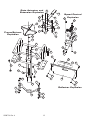
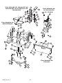
Item Part Number Qty Description
41 1008770 1 Bumper Bar
42 2M0828SS 6 1/4" x 1-3/4" Bolt, SS
43 1008711 1 Gate Actuator Bracket
44 1008712 1 Gate Actuator Extension
45 1008742-10 1 Controller Bracket
46 1001248 2 #10 x 5/8" Bolt, SS
47 1001255 4 1/4"-20 x 1" Bolt, SS
48 1001308 3 #10-24 Nylon Lock Nut,
SS
49 1001533 2 Nylon Flange Bushing
50 1007888 1 1/4" x 2-1/4" Bolt, SS
51 1008745 1 #10-24 x 2-1/4" Screw,
SS
52 1008746 1 Plastic Spacer
53 1008747 1 Grip
54 B-7181 2 1/2" Conduit Clamp
55 1008743 1 Plastic Washer

1008754 Rev. A11
1
2
4
12
12
13
23
25
29
31
29
31
42
42
5
611
21
18
14
15
19
20
16
22
10
9
24
8
7
12
Rate Gate
Explosion
Hopper
Explosion

1008754 Rev. A 12
3
45
54
31
54
43
27
51
27
31
27
31
27
48
48
48
46
46
27
31
31
27
31
27
49
27
50
47
47
52
53
44
25
55
34
10
28
26
30
33
34
35
36
39
40
42
42
37
38
41
16
16
35
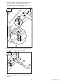
Frame/Spinner
Explosion
Defl ector Explosion
Speed Control
Explosion
Gate Actuator and
Extension Explosion

1008754 Rev. A13
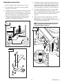
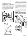
Assembly Instructions
1. Remove spreader and components from carton
2. Place spreader upside down, with top of hopper
laying on a fl at surface.
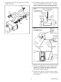
3. If spreader will be mounted onto a ZTR and the Gate
Actuator Bracket (43) will be diffi cult to reach with
foot (See Figure 1), then the Gate Actuator Extension
(44) may be required. Install the Gate Actuator
Extension to the Gate Actuator Bracket using two
1/4"-20 x 1" Bolts (47) and two 1/4"-20 Nylon
Lock Nuts (31) as shown in Figure 2.
Hard to
reach
Figure 1
31
47
44
43
Figure 2
4. If spreader will be mounted onto a vehicle and you
will use your hand to open/close the gate actuator,
install the extension as explained in Step 3. If the
extension will not fi t in your particular application, it
may be necessary to fabricate a custom extension.
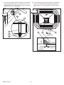
5. Turn Spyker Dial (8) to setting 9.9. Cut the cable
tie that is holding the Gate Actuator Rod (21) in
place. Slide the Gate Actuator Rod through the Gate
Actuator Bracket (43) into the position shown in
Figure 3.
6. Attach Gate Actuator Bracket (43) to the Frame
(39) using a 1/4" x 2-1/4" Bolt (50), two 1/4"
Washers (27), two Nylon Flange Bushings (49), and
a 1/4"-20 Nylon Lock Nut (31).
NOTE: Ensure that the Gate Actuator Bracket
(43) is assembled at the location and in the
orientation shown in Figure 3.
27
50
21
43
39
49
49
27
31
Figure 3

1008754 Rev. A 14
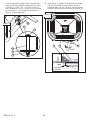
7. Attach Plastic Spacer (52) to Gate Actuator Bracket
(43) using one #10-24 x 2-1/4" Bolt (51), two 1/4"
Washers (27), and a #10-24 Nylon Lock Nut (48) as
shown in Figure 4. Leave loose.
48
27
52
27
43
51
Figure 4
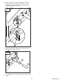
8. Pivot the Gate Actuator Bracket (43) in the direction
shown until the Rate Gate (18; See Figure 5) has
just closed but isn't pushing against the Dial Mount
(5).
Pivot
18
5 43
Close
but not
touching
Figure 5

1008754 Rev. A15
9. Adjust the position of the Plastic Spacer (52; See
Figure 6) that was assembled in Step 7 so that it
is resting against the Frame (39) and tighten the
fasteners that hold it in place.
39
52
Figure 6
10. Attach Grip (53) to Gate Actuator Extension (44, if
applicable) as shown in Figure 7.
53
44
Figure 7
11. Turn spreader over and place the Screen (2) into the
hopper.

1008754 Rev. A 16
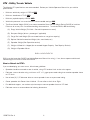
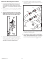
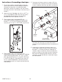
Electrical Assembly Instructions:
1. If you have purchased an optional mount kit, and
if those instructions explain how to connect and
route an electrical harness, please refer to those
instructions. If no instructions are given, continue to
Step 2.
2. Ensure spreader is attached to UTV, ATV, or ZTR per
mount kit instructions or as described previously in
this manual.
3. Attach the Controller Bracket (45) to the Variable
Speed Control (3) using two #10 x 5/8" Bolts (46)
and two #10-24 Nylon Lock Nuts (48) as shown.
3
45
54
31
54
48
48
46
46
47
4. Attach the Controller Bracket (45) to a convenient
location on your vehicle using the available 1/2"
Conduit Clamps (54), 1/4"-20 x 1" Bolts (47),and
1/4"-20 Nylon Lock Nuts (31). Ensure motor
controller will not cause a tripping hazard.
5. Plug in Motor Harness to Motor (34). The Motor
connector and Motor Harness connector can only be
attached in one way.
To Motor
To Battery
Red
Red
Black
Black
Black
Variable Speed
Control
Black
Red
Red
Motor
Harness
The motor is designed to rotate in reverse so the fan
will distribute material properly.
6. Route and plug in Motor Harness to Variable Speed
Control. Use the included Cable Ties (17) to properly
secure the Motor Harness to the vehicle. Be sure
to route wires away from hot surfaces, gas tank fi ll
areas, or areas that could cause tripping hazards.

1008754 Rev. A17
7. Plug in Battery Harness connector to the Variable
Speed Control (3).
Variable Speed
Control
Black
Black
Black
Red
Red
Red
Red
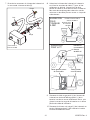
8. Route Battery Harness to battery, and use Cable
Ties (17) to properly secure to vehicle. Be sure
to route wires away from hot surfaces, gas tank fi ll
areas, or areas that could cause tripping hazard.
Mount Variable Speed
Control Here
ZTR
SUGGESTION
Fasten with
Cable Ties
UTV
SUGGESTION
Route Beneath
Bed
Route Around
Seat
Mount
Variable
Speed
Control Here
9. Connect the red positive (+) wire of battery harness
to positive (+) clamp bolt of battery. Install and
tighten nut completely, and slide red battery boot
onto positive battery cable post.
10. Connect black negative (-) battery harness to black
negative (-) of battery clamp bolt. Install and tighten
nut completely.

1008754 Rev. A 18
This page intentionally left blank.

1008754 Rev. A19
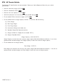
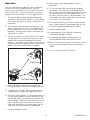
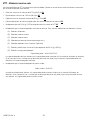
Operation
This unit is designed to handle dry, clean, free-fl owing
material only such as bagged rock salt, ice melt,
fertilizer, and grass seed. Do not use bulk rock salt or
water softener salt. It may be necessary to remove
agitator for some materials, such as bagged rock salt.
1. The recommended vehicle operating speed when
spreading is approximately 3 MPH, or slightly faster
than a brisk walk (equal to vehicle traveling 40 ft. in
9 seconds).
2. The rate gate linkage operates the rate gate. The
dial is marked from 0 to 9.9. The rate gate linkage
position determines the amount of material to be
broadcast. The higher the number, the heavier the
application of material
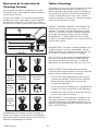
3. The dial is milled out at the 9.9 position. This allows
the rate gate link to go past the 9.9 position and
enables the rate gate to be opened to maximum
distance. This setting can be used for dry sand, dry
organic top dresses, bagged rock salt, and ice melt
products that are normally diffi cult to spread.
9.9 Setting
Full Open Setting
4. Ensure spreader and electrical harnesses are
properly attached to vehicle (see Assembly Section).
5. Fill hopper with material. Do not exceed maximum
weight capacity of hopper (see Capacity Section).
6. Set dial to correct position. If a Spyker dial setting is
not found with broadcast material information, use
the size and weight comparison table found on the
following pages. Determine a dial setting on the low
side. If the setting proves to be too low, cover the
area more than one time. A higher setting can be
used when a proven dial setting is established.
7. Travel to spreading location.
8. Ensure area surrounding spreader is clear of
bystanders.
9. Turn on/off switch ON, and adjust motor speed
control dial. The higher the motor speed control
setting, the further the broadcast distribution will be.
For most fertilizers, the motor speed control can
be set at 5 and still obtain a 18' spread width. For
grass seeds, the motor speed control can be set at
5 to obtain a 12' spread width.
10. Press the RH side of gate actuator to open hopper
gate. Open the gate of the spreader after you are
in motion at operating speed (about 3 MPH).
11. Evaluate spread pattern.
12. If spread pattern is OK, continue to spread at
recommended speed of 3 MPH.
13. If spread pattern needs to be adjusted, go to
Accuway Spread Pattern Adjustment Section.
14. Press LH side of gate actuator to close gate. Close
the gate of the spreader while still at operational
speed.
15. Turn on/off switch to OFF to stop fan.

1008754 Rev. A 20
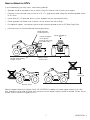
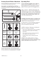
Accuway Spread Pattern Adjustment
Caution! To avoid injury to hand, ensure motor controller
is switched OFF before adjusting Accuway.
As you spread, if the spread pattern is skewing or
fl owing heavy to one side, simply loosen the T-knob (15)
on the Accuway plate (20) and slide the T-knob forwards
or backwards.
15
20
Travel
Spread
Pattern
New
Spread
Pattern
Set
Accuway
to:
Heavy to
Left Heavy to
Right
Moving the Accuway plate shifts the material on the
spinner. Adjustment is very sensitive and should be done
in small increments until the spread pattern is centered.
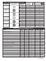
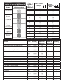
Spreading Chart
This unit is designed to handle dry, clean, free-fl owing
material only such as bagged rock salt, ice melt,
fertilizer, and grass seed. Do not use bulk rock salt or
water softener salt. It may be necessary to remove
agitator for some materials, such as bagged rock salt.
SPEED - ACCURACY - FREEDOM FROM STRIPES AND
STREAKS are yours - when you use this Spreader. The
spread width ranges from 6 ft. to 25 ft. wide, depending
on the volume/density, particle size of the material and
the rate of travel. The spread thins or feathers at the
outer edges, eliminating sharp, “Edge of spread” lines
which cause stripes and streaks.
REMEMBER- Published dial settings can be approximate
only. The operation of the spreader, the condition of the
material (damp or dry or over-pulverized) and weather
conditions, are all contributing factors.
For these reasons, it’s often a good idea to spread the
area 2 times - at one-half rate - in cross directions.
Vehicle travel speed should be 3 MPH.
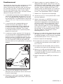
CAUTION. Avoid injury! Chemicals can be dangerous.
Avoid injury to operator or bystanders.
• Read chemical MSDS (Material Safety Data Sheets)
and container label for proper/safe handling
instructions.
• Wear appropriate clothing and safety equipment
when applying and handling chemicals.
• Prohibit smoking, drinking, and eating around
chemicals.
WARNING: When spreading products containing
herbicides, exercise extreme caution with respect to
careless spreading and to wind-drift. CONTACT OF SOME
PRODUCTS ON SOME PLANTS CAN BE FATAL.
La page est en cours de chargement...
La page est en cours de chargement...
La page est en cours de chargement...
La page est en cours de chargement...
La page est en cours de chargement...
La page est en cours de chargement...
La page est en cours de chargement...
La page est en cours de chargement...
La page est en cours de chargement...
La page est en cours de chargement...
La page est en cours de chargement...
La page est en cours de chargement...
La page est en cours de chargement...
La page est en cours de chargement...
La page est en cours de chargement...
La page est en cours de chargement...
La page est en cours de chargement...
La page est en cours de chargement...
La page est en cours de chargement...
La page est en cours de chargement...
La page est en cours de chargement...
La page est en cours de chargement...
La page est en cours de chargement...
La page est en cours de chargement...
La page est en cours de chargement...
La page est en cours de chargement...
La page est en cours de chargement...
La page est en cours de chargement...
-
 1
1
-
 2
2
-
 3
3
-
 4
4
-
 5
5
-
 6
6
-
 7
7
-
 8
8
-
 9
9
-
 10
10
-
 11
11
-
 12
12
-
 13
13
-
 14
14
-
 15
15
-
 16
16
-
 17
17
-
 18
18
-
 19
19
-
 20
20
-
 21
21
-
 22
22
-
 23
23
-
 24
24
-
 25
25
-
 26
26
-
 27
27
-
 28
28
-
 29
29
-
 30
30
-
 31
31
-
 32
32
-
 33
33
-
 34
34
-
 35
35
-
 36
36
-
 37
37
-
 38
38
-
 39
39
-
 40
40
-
 41
41
-
 42
42
-
 43
43
-
 44
44
-
 45
45
-
 46
46
-
 47
47
-
 48
48


SPYKER S80-12010 Le manuel du propriétaire
- Catégorie
- Tondeuses à gazon
- Taper
- Le manuel du propriétaire
dans d''autres langues
- English: SPYKER S80-12010 Owner's manual
Documents connexes

Autres documents
-
Kolpin 8999161 Le manuel du propriétaire
-
Rauch Zusatzblatt AXEO Rührwerk | agitator Guide d'installation
-
Agri-Fab 175# ATV Broadcast Spreader Le manuel du propriétaire
-
-
-
-
 Redexim RINK 1005 Le manuel du propriétaire
-
-
 Redexim Rink 1205 Mounted Le manuel du propriétaire
-

