Garland 36ER33-88 Owner Instruction Manual
- Catégorie
- Cuisinières
- Taper
- Owner Instruction Manual

Part # 1382670 (12/07) Page 1
Users are cautioned that maintenance and repairs must be performed by a Garland authorized service agent
using genuine Garland replacement parts. Garland will have no obligation with respect to any product that has been
improperly installed, adjusted, operated or not maintained in accordance with national and local codes or installation
instructions provided with the product, or any product that has its serial number defaced, obliterated or removed,
or which has been modified or repaired using unauthorized parts or by unauthorized service agents.
For a list of authorized service agents, please refer to the Garland web site at http://www.garland-group.com.
The information contained herein, (including design and parts specifications), may be superseded and is subject
to change without notice.
GARLAND COMMERCIAL INDUSTRIES
185 East South Street
Freeland, Pennsylvania 18224
Phone: (570) 636-1000
Fax: (570) 636-3903
GARLAND COMMERCIAL RANGES, LTD.
1177 Kamato Road, Mississauga, Ontario L4W 1X4
CANADA
Phone: 905-624-0260
Fax: 905-624-5669
Enodis UK LTD.
Swallow eld Way, Hayes, Middlesex UB3 1DQ ENGLAND
Telephone: 081-561-0433
Fax: 081-848-0041
Part # 1382670 (12/07) © 2005 Garland Commercial Industries, Inc.
FOR YOUR SAFETY:
DO NOT STORE OR USE GASOLINE
OR OTHER FLAMMABLE VAPORS OR
LIQUIDS IN THE VICINITY OF
THIS OR ANY OTHER
APPLIANCE
WARNING:
IMPROPER INSTALLATION, ADJUSTMENT,
ALTERATION, SERVICE OR MAINTENANCE
CAN CAUSE PROPERTY DAMAGE, INJURY,
OR DEATH. READ THE INSTALLATION,
OPERATING AND MAINTENANCE
INSTRUCTIONS THOROUGHLY
BEFORE INSTALLING OR
SERVICING THIS EQUIPMENT
PLEASE READ ALL SECTIONS OF THIS MANUAL
AND RETAIN FOR FUTURE REFERENCE.
THIS PRODUCT HAS BEEN CERTIFIED AS
COMMERCIAL COOKING EQUIPMENT AND
MUST BE INSTALLED BY PROFESSIONAL
PERSONNEL AS SPECIFIED.
IN THE COMMONWEALTH OF MASSACHUSETTS
THIS PRODUCT MUST BE INSTALLED BY A
LICENSED PLUMBER OR GAS FITTER. APPROVAL
NUMBER: G-1-07-05-28
For Your Safety:
Post in a prominent location, instructions to be
followed in the event the user smells gas. This
information shall be obtained by consulting
your local gas supplier.
INSTALLATION AND
OPERATION MANUAL
TM
GAS BAKE AND PIZZA
OVENS

Part # 1382670 (12/07)Page 2
IMPORTANT INFORMATION
WARNING:
This product contains chemicals known to the state of california to cause cancer and/or birth defects
or other reproductive harm. Installation and servicing of this product could expose you to airborne
particles of glass wool/ceramic fibers. Inhalation of airborne particles of glass wool/ceramic fibers
is known to the state of california to cause cancer. Operation of this product could expose you to
carbon monoxide if not adjusted properly. Inhalation of carbon monoxide is known to the state of
california to cause birth defects or other reproductive harm.
Keep appliance area free and clear of combustibles.

Part # 1382670 (12/07) Page 3
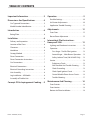
TABLE OF CONTENTS
Important Information.................2
Dimensions And Specications.........4
Gas Type and Connections...................5
Model Number Identication.................5
Introduction...........................6
Rating Plate..................................6
Installation............................6
Delivery and Inspection......................6
Location of the Oven.........................6
Clearances...................................6
Ventilation...................................6
Canopy Method .............................7
Direct Connection...........................7
Direct Connection Instructions...............7
Gas Connections.............................7
Electrical Connections .......................8
Electrical Grounding Instructions.............8
Unit Assembly...............................8
Leg Installation – All Models..................8
Assembly of Double Unit.....................8
Concept Of Air Impingement Cooking. . . 9
Operation.............................9
Possible Settings............................10
Air Shutter Adjustments.....................10
Application Trouble Shooting ...............11
Adjustments..........................12
Oven Door .................................12
Burner ame Adjustment....................12
Intermittent Pilot Instructions -
Honeywell S286 ......................13
Lighting and Shutdown Instructions.........13
Operation..................................13
First Stage – Trial for Pilot Ignition........ 13
Second Stage – Main Burner Operation . . 13
Safety Lockout Time (S86 & S86D Only). . . 13
Service.....................................13
Preliminary Check....................... 13
S86 Checkout And Trouble Shooting..... 13
Check Grounding ....................... 13
Check Spark Ignition Circuit.............. 14
Control Module Flame Sensor Circuit..... 14
Trouble Shooting........................ 17
Maintenance And Cleaning ............18
Oven Exterior...............................18
Oven Interior ...............................18
Bottom Jet Plate Installation.................18

Part # 1382670 (12/07)Page 4
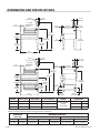
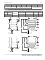
DIMENSIONS AND SPECIFICATIONS
30"
[762mm]
DECK
48-1/2"
[1232mm]
DECK
36-1/4"
[921mm]
18-1/2"
[470mm]
18-1/2"
[470mm]
18-1/2"
[470mm]
24-1/4"
[616mm]
78"
[1981mm]
101"
[2565mm]
10-3/4"
[273mm]
4-1/2"
[114mm]
45-1/4"
[1149mm]
4-1/2"
[114mm]
10-3/4"
[273mm]
4-1/2"
[114mm]
45-1/4"
[1149mm]
4-1/2"
[114mm]
9"
[229mm]
71-3/4"
[1822mm]
13-3/4"
[
349mm
]
63"
[1600mm]
42"
[1067mm]
DECK
71-1/2"
[1816mm]
94-1/2"
[2400mm]
3-3/8"
[86mm]
6" DIA
[152 mm]
6" DIA
[152 mm]
3-3/8"
[86mm]
7-1/2"
[
191mm
]
9"
[229mm]
14"
[356mm]
14"
[356mm]
65-1/4"
[1657mm]
63"
[1600mm]
3/4" NPT
REAR GAS
INLET
3/4" NPT
REAR GAS
INLET
MODEL INPUT (BTU) DECK AREA PIZZA CAPACITY MOTOR SHIPPING WT.
G56PB 80,000 14.0 Sq. Ft. (6) 18”
120V, 1Ø, 60Hz
15 Amps
(1 per deck)
1000 lbs. 455 kg
G56PT 80,000 14.0 Sq. Ft. (6) 18” 1000 lbs. 455 kg
G56PT/B 160,000 28.0 Sq. Ft. (12) 18” 2@1000 lbs. 910 kg
Gas input ratings shown here are for installations tip to 2,000 feet (610mm) above sea level.
BTU input ratings must be derated for high altitude installations.
OPERATING
PRESSURE
MINIMUM CLEARANCES
Installation to Combustible Wall Entry
Nat Pro Sides Rear Base Crated Uncrated
3.5” WC 10.0” WC 6” (152mm) 6” (152mm) 8” (203mm) 45” (1143mm) 35-1/2” (902mm)

Part # 1382670 (12/07) Page 5
SPECIFICATIONS
Gas Type and Connections
MODEL TYPE DESCRIPTION CONNECTIONS
G56T, G56B,
G56PT and G56PB
Natural or
Propane gas
Single Deck
3/4 NPT Gas Inlet Line Cord
Supplied
G56T/B
G56PTB
Natural or
Propane gas
Double Deck
(2) 3/4 NPT Gas Inlets
2 Line Cords Supplied
Model Number Identication
The model numbering system used indicates the input type,
deck size, intended application, and power module position
EXAMPLE:
G56PT
INPUT G = GAS MODEL
DECK WITH IN INCHES
TYPE OF OVEN; P = PIZZA
NO LETTER = BAKE
POWER MODULE; T = TOP
B = BOTTOM
The model number on your oven is printed on the ratings
label, located on the side of the control panel housing.

Part # 1382670 (12/07)Page 6
INTRODUCTION
Like any ne, precision built piece of equipment, your
appliance, should be given regular car and maintenance.
Periodic inspections by your local dealer or a qualied
service agent are recommended.
Rating Plate
When corresponding with the factory or your local
authorized factory service center regarding service problems
or replacement parts, be sure to refer to the particular unit
by the correct model number (including the prex and sux
letters and numbers) and the warranty serial number. The
rating plate located on the side of the control panel housing
contains this information.
We suggest installation, maintenance and repairs should be
performed by your local authorized service agency listed in
your information manual pamphlet.
In the event you have any questions concerning the
installation, use, care or service of the product, write or call
our Product Service Department.
This product must be installed by professional personnel as
specied. Garland/U.S. Range products are not approved or
authorized for home or residential use, but are intended for
commercial applications only. Garland / U.S. Range will not
provide service, warranty, maintenance or support of any
kind other than in commercial applications.
INSTALLATION
The importance of proper installation of commercial
gas cooking equipment cannot be overstressed. Proper
performance of the equipment is dependent, in great part,
on the compliance of the installation with the manufacturer’s
specications. In addition compliance with the National
Fuel Gas code ANSI Z 223.1-1988/NFPA and/or Local Code is
required to assure safe and ecient operation.
In Canada, the installation and connection must comply with
CAN/CGA – B149 Installation codes and local codes where
applicable.
All burner adjustments and setting shall be made by a
qualied gas technician.
Delivery and Inspection
Upon delivery of your GARLAND Gas AIR DECK, inspect
the carton for external damage. Uncrate oven and check
for concealed damage. Any evidence of damage should be
noted on the delivery receipt which must be signed by the
driver.
Location of the Oven
Appliances shall be installed in a location in which the
facilities for ventilation permit satisfactory combustion of gas
and proper venting. Appliances shall be located so as not to
interfere with proper circulation of air within the conned
space. When buildings are so tight that normal inltration
does not provide the necessary air, outside air shall be
introduced.
Clearances
Unit must be installed with no less than six inches (6”,
152mm) clearance from combustible construction at both
sides and rear.
Ventilation
Local codes and conditions vary greatly from one area
to another and must be complied with, following are
the minimum requirements for good ventilation. Please
remember these are general recommendations or
guidelines, you may have a special conditioner problem that
will require the services of a ventilation engineer or specialist.
Proper ventilation is the oven owner’s responsibility.
Improper ventilation can inhibit oven performance.

Part # 1382670 (12/07) Page 7
INSTALLATION Continued
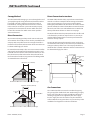
Canopy Method
The ideal method of venting a gas oven is through the use of
a properly designed canopy which should extend six inches
beyond all sides of the appliance and six feet six inches
from the oor. A strong exhaust fan will create a vacuum
in the room, for an exhaust system vent to work properly,
replacement air must enter the room in which the vent is
located. The amount of air which enters must equal the
amount exhausted.
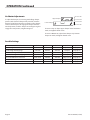
Direct Connection
An unrestricted vent pipe that provides exit air at the oven
of a minimum of 55 C.F.M. per oven must be provided for the
vent pipe at the top of the oven. The vent pipe should be a
minimum of 6” (152mm) in diameter. A direct connect kit can
be obtained through your dealer.
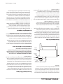
Do not Undersize Vent Pipe. This can cause resistance to ow
and impede good venting. If a horizontal run must be used
it should rise no less than 1/4” for each linear foot or run. The
ue should rise two feet to three feet above the roof line or
two feet to three feet above any portion of a building within
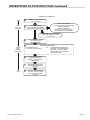
a horizontal distance of ten feet.
Termination Less than 10 feet (3 meters) from ridge
Less than 10 feet (3 meters)
2' (60cm)
Min.
3' (90cm) Min.
Termination More than 10 feet (3 meters) from ridge
More than 10' (3 meters)
3' (90cm) Min.
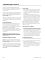
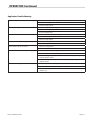
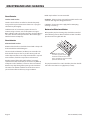
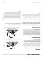
Direct Connection Instructions
The G56P-T/B (or double deck), may be direct vented to the
outside. In order to accomplish direct venting and maintain
proper oven operation, it is necessary to install a Direct
Venting Kit part #CK4529. This kit consists of a Heat Collector
(Part #1190100). The Heat Collector Box is mounted over the
ue at the rear of the oven and Draft Diverter is attached to
the top of the Heat collector as shown on next page.
The Heat Collector must be positioned over the rear ue and
as far forward as possible on top of oven. It is necessary to
mark and drill mounting holes on oven top to fasten Heat
Collector securely in place.
An unrestricted vent pipe that provides exit air at the oven
of a minimum of 55 C.F.M. per oven must be provided for the
vent pipe at the top of the oven. The vent pipe should be a
minimum of 6” (152mm) in diameter. A direct connect kit can
be obtained through your dealer.
6" Stove Pipe
Draft Diverter
Heat
Collector
Oven
Flue
Gas
Pipe
15"
10"
16"
Gas Connections
The 1” NPT inlet of the rear must be considered in piping
the gas supply for double deck units. Undersized gas supply
line(s) may restrict the gas supply and aect performance.
If other gas appliances are supplied by the same supply
line, the supply line must be sized to carry the combined
volume without causing more than 1/2” pressure drop at the
manifold of each appliance on the line at full rate.

Part # 1382670 (12/07)Page 8
The appliance and its individual shuto valve must be
disconnected from the gas supply piping system during any
pressure testing of that system at pressures in excess of
1/2 PSIG (3.45 KP2).
The appliance must be isolated from the gas supply piping
system by closing its individual manual shuto valve during
any pressure testing of the gas supply piping system at test
pressures equal to or less then
1/2 PSIG (3.45 KP2).
NOTE: During installation there will be air in the gas line. This
air will have to be bled o before ignition can be established.
The electrical ignition system has a four second lock-out as a
safety device.
Electrical Connections
A 15 AMP service must be provided for each oven. For 115
Volt usage a cord and plug is provided but connection to
the electrical service must comply with local codes or in
the absence of local codes with the National electrical code
ANSI/NFPA No. 70-1987 (or latest edition).
Each oven is electrically equipped with a cord set with a
three prong plug which ts all standard 115 Volt three prong
grounded receptacle. A wiring diagram is attached to the
rear of the unit.
POWER FAILURE: In the event of a power failure, no
attempt should be made to operate this oven. This unit is
gas operated but has electrical features, motors, controls
and burner systems.
Electrical Grounding Instructions
WARNING: All ovens, when installed, must be electrically
grounded in accordance with local codes, or in the absence
of local codes with the Nation Electrical code ANSI/NFPA 70-
1987 (or latest edition).
This appliance is equipped with a three prong (grounding)
plug for your protection against shock hazard and should be
plugged directly into a properly grounded three pronged
receptacle. Do not cut or remove the grounding prong
from this plug.
INSTALLATION Continued
Unit Assembly
1. Before assembly and connection check gas supply and
electrical service. It is recommended that a separate
electrical circuit be provided for the Air Deck. A single
unit will require 15 AMPS and a double will require a
20 AMP circuit.
2. Gas conditions for this unit are listed on the rating
plate, located just forward of the Louvered Panel of the
Power Module. If this is a new installation, have the gas
authorities check meter size and piping to assure that
existing meter and piping will supply fuel at the oven
with 3.5” W/C (for Natural Gas) or 10.0” W/C (for L.P. Gas)
and not more than 1/2” water column pressure drop.
NOTE: When checking pressure, be sure that all other
equipment on the same gas line is on. A gas pressure
regulator is built into the combination control valve and no
adjustment is needed.
Leg Installation – All Models
1. Oven is crated and shipped on its base. When uncrating,
the bottom of unit is exposed to facilitate leg installation.
Position the legs inside front and rear corners from frame.
Start each bolt, threading them into the weld nuts on
the base frame. Four (4) bolts with washers must be used
to secure each leg in place. Tighten the bolts evenly and
securely. The legs are interchangeable front to back, for
models “B” – longer legs for left side – shorter legs for
mounting to Power Module section: See line drawing.
Assembly of Double Unit
1. Install legs on bottom unit. Then place in position desired.
2. Place 2 x 4’s on top of the lower section about six inches
from each side, running front to rear.
3. Raise the top section and position it on the 2 x 4’s so that
the front, rear and sides of top section with the lower
oven section. Carefully remove the 2 x 4’s lowering the
upper oven into place. It is not necessary to bolt the
sections together.

Part # 1382670 (12/07) Page 9
CONCEPT OF AIR IMPINGEMENT COOKING
The “AIR DECK” Oven produced by GARLAND COMMERCIAL
INDUSTRIES INC., utilizes a revolutionary cooking concept,
called “AIR IMPINGEMENT”. It provides exceptional baked
food product quality in far less time than conventional
devices on the market. The “AIR IMPINGEMENT” system
directs a high velocity stream of heated air at the food
product being baked.
This blast eect penetrates the boundary layer of air
encircling the product and heats the food more eciently,
because the air concentrates heat on the food product.
Greater heat transfer rates, results in products baking two to
four times faster than conventional means, are possible with
“AIR IMPINGEMENT”.
The “AIR IMPINGEMENT” process develops the high velocity
air stream with a specially designed fan that draws super-
heated air from a heat source (either gas or electric). This
air is directed through a plenum chamber to patented “JET
PLATES” which have hundreds of focused jet ports that
“impinge” the heated air onto the food product surface. The
heated air is re-cycled to the heat source after striking the
food product, thus reducing energy consumption.
The “AIR IMPINGEMENT” process is tolerant enough for
sensitive food products and eects proper crisping and even
browning of such products as they pass through the oven,
because air is the medium which heats the food product. The
adjustable air controls for top and bottom jet plates allow
further enhancement of cooking.
OPERATION
Once the equipment has been installed and tested by
qualied professional personnel, the oven is ready for
operation.
Many of the parts used in the oven have a thin protective
oil covering. The oil should be burned o before the oven is
used for the production of food products. It is normal for the
unit to smoke while burning o excess oil. Washing the deck
of the oven with a damp clean cloth and mild soap solution
will remove some of the protective oil coating.
To start the oven, switch the power to on. Set oven
temperature dial to 400 degrees and let oven heat and
operate at this temperature for at least one hour.
The “Air Deck” utilizes an automatic ignition and pilot
ame sensing system. During normal operation, the power
burner will cycle on and o as necessary to maintain oven
temperature. There is a short “time delay” built into the
circuitry, and you should not be alarmed when the oven
“calls for heat” and the power burner does not operate
immediately.
You will nd that cooking with the “Air Deck” oven will be
much faster than the standard Bake/Roast and Pizza Ovens.
You will have to experiment with your recipes to become
accustomed to this new method. For example the warm-
up time is shorter than standard ovens. The oven can be
warmed and ready for use in as little as twenty (20) minutes.
A large pizza can be ready to serve in as little as ve (5)
minutes. These are “ideal conditions” times and will vary with
ventilation and use.
Heat control vent shutters (2), are located on the right side of
the oven cavity. These shutters must be adjusted to provide
the air ow top and bottom that you desire for your cooking
needs. Adjusting these shutters will provide you with many
cooking variations.
If unit fails to operate, it is recommended that only qualied
service personnel perform the repairs on this unit. A
troubleshooting chart is provided in this manual to assist
qualied service personnel in repair of the unit. However,
before you call a service technician you may want to make a
few simple checks. Make sure electricity and gas are available
to the oven prior to calling a Service Technician.
CAUTION: Disconnect power supply before attempting to
clean or service.

Part # 1382670 (12/07)Page 10
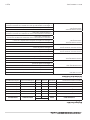
Possible Settings
PIZZA PRODUCT TIME TEMP F TEMP C UPPER LOWER
Fresh Dough Cheese Pizza 6:00-7:00 450-575 234-250 Fully Closed Fully Open
Fresh Dough with Toppings 7:30-8:30 450-475 234-250 1/2 Open Fully Open
Pre-Baked Dough Cheese Pizza 5:00-6:00 450-475 234-250 1/2 Open Fully Open
Pre-Baked Dough with Toppings 5:30-6:30 450-475 234-250 1/2 Open Fully Closed
Pre-Cooked Black Porcelain Pan 10:00-12:00 475-500 250-260 Fully Closed Fully Open
Deep Pan Pizza 8:30-9:30 475-500 250-260 Fully Closed Fully Open
Pre-Baked Party Pizza 16:00-20:00 475-500 250-260 Fully Closed Fully Open
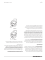
Air Shutter Adjustments
To adjust the dampers, loosen wing nut holding damper
position, with deck and damper tool provided, insert the
damper end of the tool into the receptacle on the damper,
and raise the damper to disengage the damper from the
notched position, slide the damper at a 45 degree angle to
engage the next position, retighten wing nut.
OPERATION Continued
Decrese Air
Decrese Air
Increase Air
Increase Air
Upper Damper
Lower Damper
To increase Top air, adjust upper damper “down”. Position in
notch, and tighten thumb screw.
To increase Bottom Air, adjust lower damper “up”. Position
damper in notch, and tighten thumb screw.

Part # 1382670 (12/07) Page 11
OPERATION Continued
Application Trouble Shooting
Dark Pizza Top 1 Decrease top air by adjusting upper damper “up”
2 Decrease cooking time
3 Decrease temperature.
Pizza Top Too Light 1 Increase top air by adjusting upper damper “down”.
2 Increase cooking time
3 Increase temperature.
Pizza Bottom too Dark 1 Decrease bottom air by adjusting lower damper “down
2 Decrease cooking time
3 Decrease temperature
Pizza Bottom and Top Too Light 1 Increase cooking time
2 Increase temperature
Pizza bottom and Top Too Dark 1 Decrease cooking time
2 Decrease temperature
Pizza Bottom Too Dark and Top too Light 1 Increase top air by adjusting top damper “down”
2 Decrease bottom air by adjusting bottom damper “down”
3 Lower cooking temperature and decrease bottom air by adjusting
bottom damper “down”
4 Lower cooking temperature and increase top air by adjusting top
damper “down”
Pizza Bottom Too Light and Top Too Dark 1 Decrease top air by adjusting top damper “up”
2 Increase bottom air by adjusting bottom damper “up”
3 Increase cooking temperature and decrease top air by adjusting upper
damper “up”.

Part # 1382670 (12/07)Page 12
NOTE: Each oven has been factory tested and adjusted
prior to shipment. It may be necessary to further adjust
the oven as part of a proper installation. Such adjustments
are the responsibility of the installer. Adjustments are not
considered defects in material or workmanship, and they are
not covered under the original equipment warranty.
Oven Door
The “AIR DECK” oven door has adjustability as a design
feature. Although it is factory set, the tension can be adjusted
to suit the operator’s preference. In addition, after a long
period of hard use, the tension can be readjusted as required.
To adjust door tension it is necessary to remove left and
right front corners of unit by the two sheet metal screws.
This exposes the door hinge and spring assembly. The spring
hook passed through a bracket. A 1/4” x 20 nut is on the
spring hook forward of the bracket. If it is available, use a
7/16” deep socket and ratchet to turn the nut clockwise to
increase spring tension or counter-clockwise to relieve spring
tension. Make sure to adjust both sides equally.
The oven door is properly adjusted if the door remains fully
open and if the spring tension carries the door to the full
closed position from the half-closed position. Replace the
corner and fasten with screws.
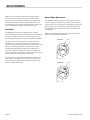
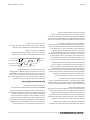
Burner ame Adjustment
The “AIR DECK” utilizes a power burner assembly as a heat
source. To ensure peak eciency, a proper air-fuel mixture is
necessary. There is an inspection port (window) on the power
burner. There is an air shutter located on the blower motor
that should be adjusted to provide a good blue ame with
no yellow tips.
Below is a drawing illustrating the proper way to check the
burner blower air shutter adjustment.
NATURAL
7/8"
PROPANE
1/2"
ADJUSTMENTS

Part # 1382670 (12/07) Page 13
INTERMITTENT PILOT INSTRUCTIONS - HONEYWELL S286
Lighting and Shutdown Instructions
Starting Burner
1. Turn the gas valve control knob to “OFF” wait ve
minutes.
2. Turn gas valve control knob to “ON”.
3. Turn power switch to “ON”, fan will turn on.
4. Turn thermostat to desired temperature setting.
5. If the burner does not light, turn the thermostat to “OFF”
and wait ve minutes then repeat step (4).
Shutting Burner Down
1. Turn thermostat to “OFF”.
2. Turn power switch to “OFF”.
3. Turn gas valve control knob to “OFF”.
4. Turn main shuto valve to “OFF”.
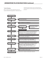
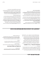
Operation
First Stage – Trial for Pilot Ignition
On every call for heat (system start), the S86 performs an
internal safe-start check shows that a ame-simulating
condition is present.
During a normal start, the S86 opens the rst operator in
the gas control. This allows gas to ow to the pilot burner.
Simultaneously, the electronic spark generator in the S86
produces a 30,000 volt spark pulse output. This voltage
produces a spark at the pilot burner ignitor/sensor rod,
igniting the gas owing around the electrode. If the pilot
ame is not detected during the trial for pilot ignition, the
S86A and B will continue trying for pilot ignition until a ame
is established. The S86C and D contain a safety lockout timer
to limit the trial for pilot ignition period.
Second Stage – Main Burner Operation
When the pilot ame is established, a ame rectication
circuit is completed to the burner ground. The S86 ame
sending circuit detects the ame current and shuts the
spark generator o. At the same time the second operator
(main) is opened in the gas control, allowing fast ow to
the main burner. The pilot ame ignites the main burner
conventionally. On the S86C and D the ame current also
holds the safety lockout timer in the reset, or normal,
operating condition.
Safety Lockout Time (S & SD Only)
The safety lockout timer circuit starts timing the moment
the trial for pilot ignition starts. When the timing period runs
out, the trial for ignition ends, and the control module goes
into lockout. Before another attempt to start can be made
the S86 must be reset. Reset by adjusting the thermostat or
controller below room temperature, or to its “OFF” position.
An alternate method is to shut the system power “OFF”. If
normal ignition does not occur, use the trouble shooting
table to determine the problem.
Service
Preliminary Check
The following visual checks should be made before trouble
shooting and after installation of maintenance.
1. Check power to appliance and S86
2. Manual shuto cocks in gas line to appliance must be
open.
3. Make certain all wiring connections are clean and tight.
4. S86C & D module must not be in safety lockout. First de-
energize the system and wait at least one (1) minute. This
resets the module allowing a return to start condition.
Then energize the system.
5. Review the S86 system normal sequence of operation.
S Checkout And Trouble Shooting
NOTE: On servicing S86A, B, C and D models.
The S86E, F, G and H models can be used to directly replace
S86A, B, C and D models (E replaces A model, F replaces B, G
replaces C model and H replaces D model) and the S86B and D
can be used to replace S86F and H, respectively. However, the
S86A and C cannot be used to replace the S86E and G module
on IPI systems that use VR8520 gas controls. VR8440 or VR8520
valves will not function properly with the S86A or C.
Check Grounding
A common ground is required for the pilot burner, the
ignitor-sensor, the GND terminal of the S86, and the main
burner. The main burner generally serves as the common
ground. If the ground is poor or erratic, safety shutdowns
may occur occasionally even though operation is normal at
the time of the checkout. Therefore, if nuisance shutdowns
have been reported, be sure to check the grounding.

Part # 1382670 (12/07)Page 14
INTERMITTENT PILOT INSTRUCTIONS Continued
Note: If the ground circuit path is incomplete the S86C, D, G
and H system control will allow one trial-for-ignition before
going into safety lockout.
Electrical grounding connections at the pilot burner,
ignitor/sensor and S86 must be clean and tight. If lead wire
is damaged or deteriorated, use only No. 14 of 18 gauge,
moisture-resistant, thermoplastic insulated wire with
105C. (221 F) minimum rating as replacement. Excessive
temperature at the ceramic ame rod insulator can also
permit electrical leakage to ground. Examine the ame rod
and mounting bracket, and correct if bent out of position.
Replace Q345, Q346 Q348 or ignitor/sensor if insulator is
cracked.
Check Spark Ignition Circuit
The electronic module and step-up transformer in the S86
provides spark ignition at 15,000 Volts (open circuit). This
circuit can be checked at the S86 module as follows:
1. Turn o the manual gas cock to prevent the ow of gas.
2. Disconnect the ignition cable at the S86 stud terminal to
isolate the circuit from the pilot burner/ignitor/sensor,
and prepare a short jumper lead using heavily insulated
wire, such as ignition cable.
3. Energize the S86, touch one end of the jumper rmly to
the S86 ground terminal (GND). Do not disconnect the
existing ground lead. Move the free end slowly toward
the stud terminal to establish a spark and then pull the
lead wire slowly away from the stud. Note the length of
the gap at which arcing stops.
CAUTION: Do not touch either stripped end of jumper or
stud terminal. This is a very high voltage circuit and electrical
shock can result. Perform the test immediately upon
energizing the system – before the S86C,D,G goes into safety
lockout and interrupts the spark circuit.
4. An arc length of 1/8” (3.2 mm) or more indicates
satisfactory voltage output. Replace the S86 if not arc can
be established or the maximum gap is less then 1/8” (3.2
mm), and the fuse and power to the S86 input terminal
was okay.
Control Module Flame Sensor Circuit
The control module provides AC power to the ignitor/sensor
which the pilot burner ame recties to direct current. If the
ame signal back to the control module is not at least 1.5 μA
DC, the system will lockout. The output of the ame sensing
circuit cannot be checked directly, so check the ame
sensing circuit indirectly by checking the ame sensing
current from the ignitor/sensor to the control module as
follows.
1. Connect a meter (DC micrometer scale) in series with
the ame signal ground wire as shown below. Use the
Honeywell W136A Test Meter, or equivalent. Disconnect
the ground wire at the control module.
Connect the red (positive) lead of the meter to the free
end of the ground wire. Connect the black (negative)
meter lead to the quick-connect ground terminal on the
control module.
2. Restart the system and read the meter. The ame sensor
current must be at least 1.5μA, and the reading must be
steady. If the reading is below the value designated or the
reading is unsteady, check the pilot ame and electrical
connections as described above. Also, replace the ignitor/
sensor if the ceramic insulator is cracked.

Part # 1382670 (12/07) Page 15
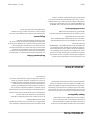
THERMOSTAT (CONTROLLER)
CALLS FOR HEAT
1
SAFE-START CHECK
MUST NOT BE ANY FLAME OR
FLAME SIMULATING CONDITION
SPARK GENERATOR POWERED
FIRST VALVE (PILOT)
OPERATOR OPENS
2
POWER INTERRUPTION
SYSTEM SHUTS OFF, RESTARTS WHEN
POWER IS RESTORED.
PILOT FLAME FAILURE
SECOND MAIL OPERATOR CLOSES,
S86 STARTS TRAIL FOR IGNITION
3
IF FLAME OR FLAME SIMULATION
CONDITION PRESENT SYSTEM
FAILS TO START
4
PILOT BURNER LIGHTS
S86 SENSES FLAME CURRENT
PILOT BURNER OPERATION
OR
PILOT BURNER DOES NOT LIGHT
S86A OR B - TRIAL FOR IGNITION
CONTINUES, S86C OR D - GOES
INTO LOCKOUT AFTER TRIAL FOR
IGNITION TIMES OUT.
IF FLAME CURRENT SENSED
SPARK GENERATOR OFF.
SECOND VALVE OPERATOR
(MAIN) OPENS
5
6
MAIN BURNER OPERATION
S86 MONITORS PILOT FLAME
CURRENT
7
THERMOSTAT (CONTROLLER)
SATISFIED - VALVES CLOSED
PILOT AND MAIN BURNERS
ARE OFF.
START
STAGE 1
TRAIL FOR
IGNITION
STAGE 2
MAIN
BURNER
OPERATION
END
SEQUENCE OF OPERATION
INTERMITTENT PILOT INSTRUCTIONS Continued

Part # 1382670 (12/07)Page 16
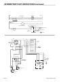
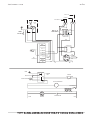
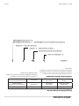
INTERMITTENT PILOT INSTRUCTIONS Continued
SWITCH
CENTRIFUGAL
CONTROL
SB6
25V
25V
GND
MAIN GAS VALVE
PILOT VALVE
MOTOR RELAY COIL
THERMOSTAT
TRANSFORMER
NEUT
HOT
MOTOR RELAY
MOTOR
EP SYSTEM
HONEYWELL
SWITCH
CENTRIFUGAL
TO ELECTRODE
BLUE
WHT
RED
GND
PV
MV/PV
MV
SB6
HONEYWELL
24V
RED
RED YEL
YEL
MOTOR
BLK
BLK
BLK
MOTOR RELAY
WHT
YEL
BLK
BLK
TH/TR
TRTH
VALVE
GAS
YEL
BLK
TRANSFORMER
L2
L1
TT
TO THERMOSTAT
115V SUPPLY
COMMON
TO LINE
"A"
CORD
24V
TH-W
SPARK
12 34567 98

Part # 1382670 (12/07) Page 17
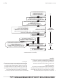
INTERMITTENT PILOT INSTRUCTIONS Continued
NO
NO
NO
NO
NO
NO
NO
NO
START
TROUBLE SHOOTING
Yes
Yes
Yes
Yes
Yes
Yes
Yes
Yes
Yes
IS POWER ON -
MEASURE 25 V
THERMOSTAT CALLS
FOR HEAT
SPARK ACROSS
IGNITER / SENSOR GAP
PILOT BURNER LIGHTS
SPARK STOPS WHEN
PILOT IS LIT
MAIN BURNER LIGHTS
SYSTEM RUNS UNTIL
CALL FOR HEAT ENDS
CALL FOR HEAT ENDS:
SYSTEM SHUTS OFF
TROUBLE SHOOTING ENDS
CHECK LINE VOLTAGE POWER, LOW VOLTAGE TRANSFORMER,
AND LOW VOLTAGE WIRING.
CHECK THERMOSTAT AND CONTROLLERS.
PULL IGNITION LEAD
AND CHECK SPARK AT
IGNITION STUD.
CHECK IGNITION CABLE,
GROUND WIRING, ELECTRODE
CERAMIC INSULATOR AND
GAP AND CORRECT.
CHECK THAT ALL MANUAL GAS COCKS ARE OPEN, SUPPLY
TUBING AND PRESSURES ARE GOOD, AND PILOT BURNER ORIFICE
IS NOT BLOCKED. CHECK ELECTRICAL CONNECTIONS BETWEEN
CONTROL AND PILOT OPERATOR ON GAS CONTROL. CHECK FOR
24 V AT TERMINALS 1 & 5, IF NO VOLTAGE REPLACE CONTROL.
REPLACE
CHECK CONTINUITY OF IGNITION CABLE AND GROUND WIRE.
CHECK THAT PILOT FLAME COVERS BOTH ELECTRODES. IF
CHECKS ARE OKAY, REPLACE MODULE.
CHECK FOR 24 V AT TERMINALS 3 & 5. IF NO VOLTAGE REPLACE
MODULE. CHECK ELECTRICAL CONNECTIONS BETWEEN
MODULE AND GAS CONTROL. IF OKAY, REPLACE GAS CONTROL.
CHECK CONTINUITY OF IGNITION CABLE AND GROUND WIRE.
NOTE: IF GROUND IS POOR OR ERRATIC SHUTDOWNS MAY OCCUR
OCCASIONALLY EVEN THOUGH OPERATION IS NORMAL AT THE
TIME OF THE CHECKOUT. CHECK FOR EXCESSIVE HEAT AT
ELECTRODE INSULATOR (TEMPERATURE ABOUT 600° F (315° C)
CAUSES SHORT TO GROUND). IF CHECK ARE OKAY, REPLACE
MODULE.
CHECK FOR PROPER THERMOSTAT OR CONTROLLER
OPERATION REMOVE AT MODULE; IF VALVE CLOSES, REPLACE
MODULE, IF NOT, REPLACE GAS CONTROL.
REPEAT PROCEDURE UNTIL TROUBLE FREE OPERATION IS OBTAINED.
NO
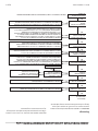
Trouble Shooting
NOTE: The Electronic S86 Control Module cannot be
repaired. If troubleshooting indicates a malfunction in the
S86 the S86 module must be replaced. Intermittent pilot
systems should be serviced only by trained and experienced
personnel.

Part # 1382670 (12/07)Page 18
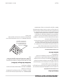
MAINTENANCE AND CLEANING
Oven Exterior
Stainless Steel Surface
Stainless Steel surfaces can often be cleaned adequately
using a mild soap and warm water solution on a sponge or
soft cloth. Dry Thoroughly.
Stubborn stains or heat tint may require the use of a
commercial type cleaner, such as Penny-Brite or Copper-
Brite, rubbed in with a dry cloth or Stainless Steel pad. Always
rub in the direction of the polished lines. Rinse thoroughly
with fresh water and wipe dry.
Oven Interior
Aluminied Steel Surfaces
Aluminied Steel Surfaces should be cleaned with a damp soft
cloth and mild household detergent.
The oven deck and bottoms (Jet Plates) are removable. The
deck should be kept as clean as possible. Heavy spills and
carbon deposits, that are not easily removed with a soap and
water solution, should be scraped loose and removed.
Periodic removal of the deck and “Jet Plates” is strongly
recommended. This will enable you to remove any build-up
of deposits on the “Jet Plates”, and access the oven bottoms.
Particles may drop through the openings in the “Jet Plates”.
The entire oven bottom should be cleaned at least once a
year and more often under heavy usage conditions.
NOTE: Top “Jet Plates” are not removable.
WARNING: Failure to clean oven perforated deck surface and
“Jet Plate” will degrade baking performance
CAUTION: disconnect power supply before attempting
cleaning or servicing.
Bottom Jet Plate Installation
After periodic jet plate cleaning, they should be reinstalled
in the following manner. Plate marked “R or “RHT” should be
placed into unit on right hand side.
R
H
T
Note: The short sided
end of the jet plate shown
should be installed in the center
of the unit with the short end down
(toward bottom of unit)
The jet plate marked “L” or “LHT” should be placed on the left
side in the same manner as right plate (see note).

Pièce n° 1382670 (12/07)Page 18
ENTRETIEN ET NETTOYAGE
Extérieur Du Four
Les Surfaces En Acier Inoxydable.
Les surfaces en acier inoxydable peuvent être nettoyées avec
une solution d’eau tiède et de savon doux sur une éponge ou
un chi on doux. Sécher soigneusement.
Les taches rebelles et la coloration due à la chaleur peuvent
nécessiter l’utilisation d’un nettoyeur commercial, tel que «
Penny-Brite » ou
« Copper-Brite », appliqué avec un linge sec ou un tampon
d’acier inoxydable. Toujours frotter dans le sens du grain
du métal. Bien rincer avec de l’eau fraîche et assécher
complètement.
Intérieur Du Four
Les Surfaces En Métal Aluminé
Les surfaces en Métal Aluminé devraient être nettoyées avec
un linge humide et un détersif domestique doux
Les plaques (Jet Plates) et pont du four sont amovibles. Le
pont devrait être gardé propre autant que possible. Des
débordements épais et des dépôts charbonneux qui ne
peuvent être facilement enlevés avec du savon et de l’eau
devraient être grattés et enlevés.
L’enlèvement périodique du pont et des plaques « Jet Plates
» est vigoureusement recommandé. Ceci vous permettra
d’enlever toute accumulation de dépôts sur les plaques «
Jet Plates » et accéder aux fonds du four. Des gouttelettes
peuvent dégoutter par les ouvertures dans les plaques. Le
fond du four en entier devrait être nettoyé au moins une fois
par année et plus souvent si le four est utilisé abondamment.
NOTE : Les plaques supérieures ne sont pas démontables.
AVERTISSEMENT : si la surface perforée du pont ainsi que les
plaques « Jet Plates » ne sont pas nettoyées, la performance
de cuisson sera réduite.
PRUDENCE : débrancher l’alimentation électrique avant de
nettoyer ou de réparer.
Installation Des Plaques (Jet Plates)
Après un nettoyage pèrioduque, les plaques devarient être
réinstallées de la manière suivante: La plaque identi ée « R
» ou « RHT » devrait être placée dans l’appareil, sur le côté
droit.
R
H
T
NOTE: Le côté étroit
de la plaque illustrée
doit être installé au centre
de l'appareil et vers le bas
(vers la base le l'appareil).
La plaque identi ée « L » ou « LHT » devrait être placée sur le
côté gauche, de la même manière que la plaque droite
(voir « note »).

Pièce n° 1382670 (12/07) Page 17
Non
Non
Non
Non
Non
Non
Non
Non
Oui
Oui
Oui
Oui
Oui
Oui
Oui
Oui
Oui
EST-CE QUE LA TENSION
DU COURANT EST 25V
THERMOSTAT FAIT UNE
DEMANDE DE CHALEUR
ÉTINCELLE ENTRE
L'ÉCART À
L'ALLUMEUR/DÉTECTEUR
BRÛLEUR DE VEILLEUSE
ALLUME
ÉTINCELLE S'ARRÊTE
LORSQUE LA VEILLEUSE
EST ALLUMÉE
BRÛLEUR PRINCIPAL
ALLUME
SYSTÈME FONCTIONNE
TANT QU'IL Y A UNE
DEMANDE DE CHALEUR
DEMANDE DE CHALEUR
ARRÊTE:
SYSTÈME ARRÊTE
FIN DE LA RECHERCHE
DE PANNES
VÉRIFIER LA TENSION DE LA LIGNE DE L'ALIMENTATION ÉLECTRIQUE,
TRANSFORMATEUR DE BASSE TENSION ET FIL ÉLECTRIQUE DE BASSE TENSION
VÉRIFIER LE THERMOSTAT ET LES CONTRÔLEURS.
TIRER LA CONDUITE
D'ALLUMAGE ET VÉRIFIER
L'ÉTINCELLE AU PLOT
D'ALLUMAGE
VÉRIFIER LE CABLE D'ALLUMAGE,
FIL DE LA MISE-À-LA-TERRE,
ISOLATEUR EN CÉRAMIQUE
DE L'ÉLECTRODE ET L'ÉCART ET CORRIGER.
VÉRIFIER SI TOUTES LES VANNES À GAZ MANUELLES SONT OUVERTES, SI LA
TUYAUTERIE D'ALIMENTATION ET LES PRESSIONS SONT BONNES, ET SI LA BUSE
DU BRÛLEUR DE LA VEILLEUSE EST BOUCHÉE. VÉRIFIER LES CONNEXIONS
ÉLECTRIQUES ENTRE LE RÉGULATEUR ET L'ACTIONNEUR DE VEILLEUSE DU
RÉGULATEUR À GAZ. VÉRIFIER SI LA TENSION AUX BORNES 1 & 5 EST 24V. SI
AUCUNE TENSION, REMPLACER LE RÉGULATEUR.
REMPLACER
VÉRIFIER LA CONTINUITÉ DU CABLE D'ALLUMAGE ET DU FIL DE LA
MISE-À-LA-TERRE. VÉRIFIER SI LA FLAMME DE LA VEILLEUSE COUVRE LES DEUX
ÉLECTRODES. SI LES VÉRIFICATIONS SONT EN RÈGLE, REMPLACER LE MODULE.
VÉRIFIER SI LA TENSION AUX BORNES 3 & 5 EST 24V. SI AUCUNE TENSION,
REMPLACER LE MODULE. VÉRIFIER LES CONNEXIONS ÉLECTRIQUES ENTRE
LE MODULE ET LE RÉGULATEUR À GAZ. SI EN RÈGLE, REMPLACER
LE RÉGULATEUR À GAZ.
VÉRIFIER LA CONTINUITÉ DU CABLE D'ALLUMAGE ET DU FIL DE LA
MISE-À-LA-TERRE. NOTE: SI LA MISE-À-LA-TERRE EST FAIBLE ET IRRÉGULIÈRE,
DES ARRÊTS PEUVENT SE PRODUIRE OCCASIONNELLEMENT MÊME SI LE
FONCTIONNEMENT EST NORMAL AU MOMENT DE LA VÉRIFICATION. VÉRIFIER
S'IL Y A UNE CHALEUR EXCESSIVE À L'ISOLATEUR DE L'ÉLECTRODE
(TEMPÉRATURE SUPÉRIEURE À 600°F (315°C) CAUSE UN COURT-CIRCUIT À LA
MISE-À-LA-TERRE). SI LES VÉRIFICATIONS SONT EN RÈGLE,
REMPLACER LE MODULE.
VÉRIFIER LE FONCTIONNEMENT DU THERMOSTAT OU CONTRÔLEUR. ENLEVER
LA CONDUITE AU MODULE; SI LA VANNE SE FERME, REMPLACER LE MODULE,
SINON REMPLACER LE RÉGULATEUR À GAZ.
RÉPÉTER LE PROCESSUS JUSQU'À L'OBTENTION D'UN FONCTIONNEMENT NORMAL.
Non
DÉBUT DE LA
RECHERCHE DE
PANNES/SOLUTIONS
Dépannage
IMPORTANT : Le Module de Régulation Électronique S86 ne
peut être réparé. Si le processus de recherche de pannes
indique un mauvais fonctionnement du S86, le Module de
Régulation S86 doit être remplacé. Le service sur les systèmes
à veilleuse intermittente devrait être e ectué seulement par
du personnel entraîné et expérimenté.
DIRECTIVES POUR LA VEILLEUSE INTERMITTENTE suite
La page est en cours de chargement...
La page est en cours de chargement...
La page est en cours de chargement...
La page est en cours de chargement...
La page est en cours de chargement...
La page est en cours de chargement...
La page est en cours de chargement...
La page est en cours de chargement...
La page est en cours de chargement...
La page est en cours de chargement...
La page est en cours de chargement...
La page est en cours de chargement...
La page est en cours de chargement...
La page est en cours de chargement...
La page est en cours de chargement...
La page est en cours de chargement...
-
 1
1
-
 2
2
-
 3
3
-
 4
4
-
 5
5
-
 6
6
-
 7
7
-
 8
8
-
 9
9
-
 10
10
-
 11
11
-
 12
12
-
 13
13
-
 14
14
-
 15
15
-
 16
16
-
 17
17
-
 18
18
-
 19
19
-
 20
20
-
 21
21
-
 22
22
-
 23
23
-
 24
24
-
 25
25
-
 26
26
-
 27
27
-
 28
28
-
 29
29
-
 30
30
-
 31
31
-
 32
32
-
 33
33
-
 34
34
-
 35
35
-
 36
36


Garland 36ER33-88 Owner Instruction Manual
- Catégorie
- Cuisinières
- Taper
- Owner Instruction Manual
dans d''autres langues
- English: Garland 36ER33-88
